
Central Gemini IV - Range hood Thermex - Free user manual and instructions
Find the device manual for free Central Gemini IV Thermex in PDF.


| Product Type | Island range hood |
| Model | Central Gemini IV |
| Brand | Thermex |
| Dimensions (W x D x H) | 90 cm x 50 cm x 50-100 cm (adjustable height) |
| Weight | Approx. 25 kg |
| Power Supply | 220-240 V, 50/60 Hz |
| Maximum Airflow | 650 m³/h |
| Noise Level | 45-65 dB(A) |
| Control Type | Touch control panel |
| Lighting | LED strip, dimmable |
| Number of Speeds | 3 + intensive boost |
| Filter Type | Aluminum grease filter |
| Filter Cleaning | Dishwasher safe |
| Exhaust Type | Ducted or recirculation (with carbon filter) |
| Energy Class | A+ |
| Annual Energy Consumption | 35 kWh/year (average) |
| Safety Features | Auto shut-off, thermal protection, child lock |
| Maintenance | Clean grease filter monthly; replace carbon filter every 3-6 months |
| Spare Parts Availability | Filters, bulbs, motors available from Thermex service |
| Warranty | 2 years standard |
Frequently Asked Questions - Central Gemini IV Thermex
User questions about Central Gemini IV Thermex
0 question about this device. Answer the ones you know or ask your own.
Ask a new question about this device
Download the instructions for your Range hood in PDF format for free! Find your manual Central Gemini IV - Thermex and take your electronic device back in hand. On this page are published all the documents necessary for the use of your device. Central Gemini IV by Thermex.
USER MANUAL Central Gemini IV Thermex
Fig.2
natural_image
Simple line drawing of a cabinet with two doors and a central opening (no text or symbols)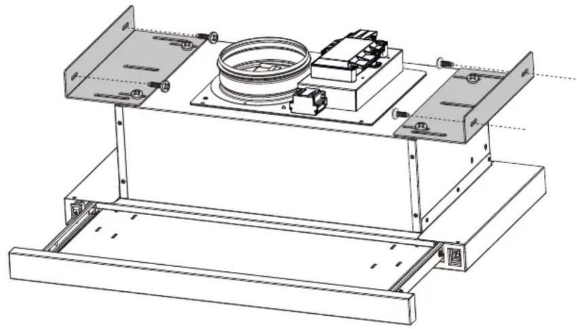
natural_image
Technical line drawing of a mechanical assembly with mounting brackets and a central circular component (no text or symbols)
Fig.3
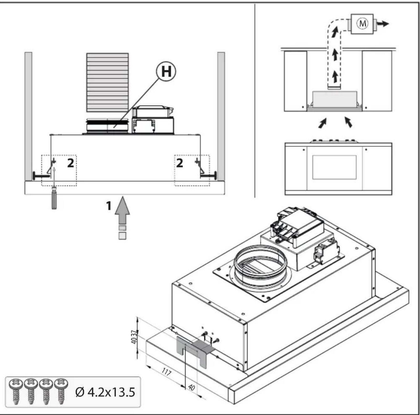
Fig.4
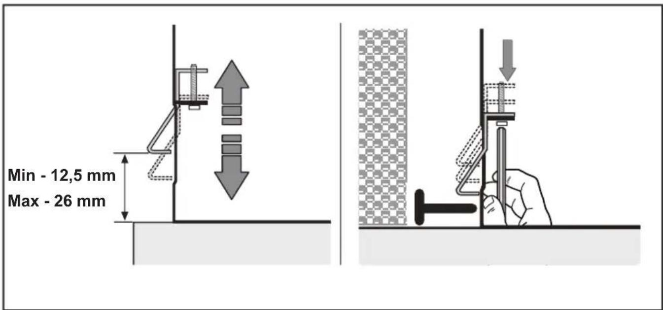
Fig.5
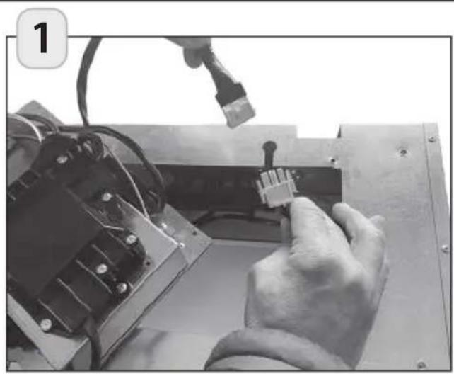
natural_image
Close-up of hands operating a mechanical assembly with a connector, no visible text or symbols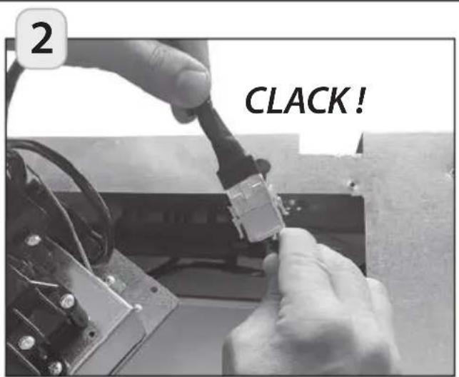
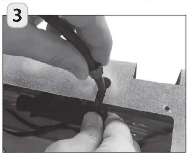
natural_image
Close-up of hands using a tool to cut or mark a metal component, no visible text or symbols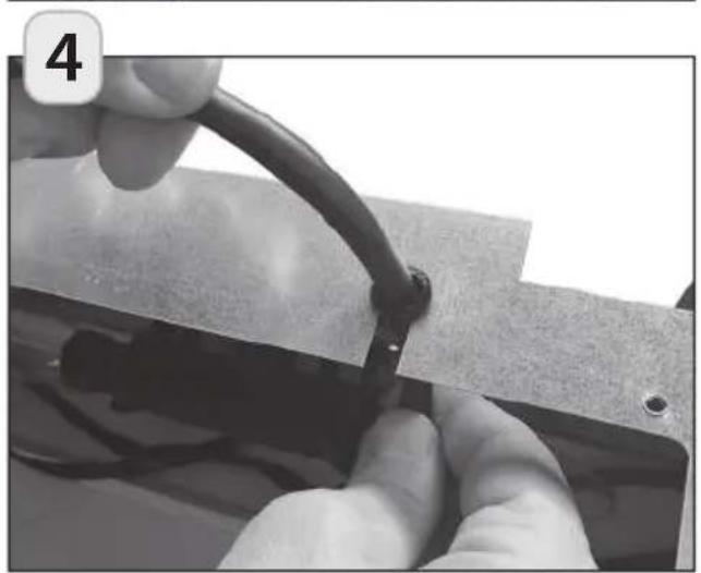
natural_image
Close-up of hands holding a flexible wire with a black clip, no visible text or symbols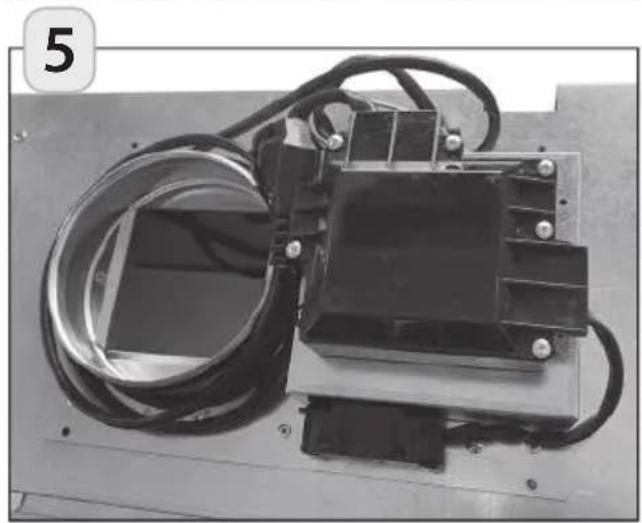
natural_image
Industrial electrical component with coiled wires and a rectangular housing (no visible text or symbols)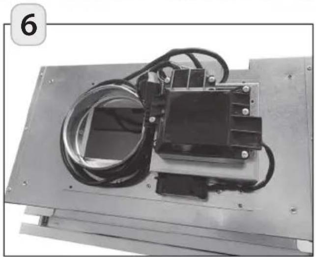
natural_image
Exterior view of a mechanical device with coiled wires and a central component (no visible text or symbols)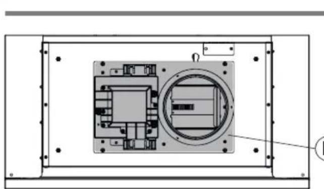
natural_image
Technical diagram of a mechanical or electronic component with internal components and mounting holes (no text or symbols)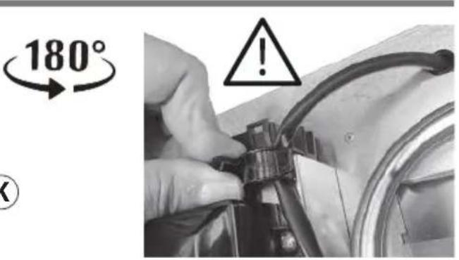
Fig.6
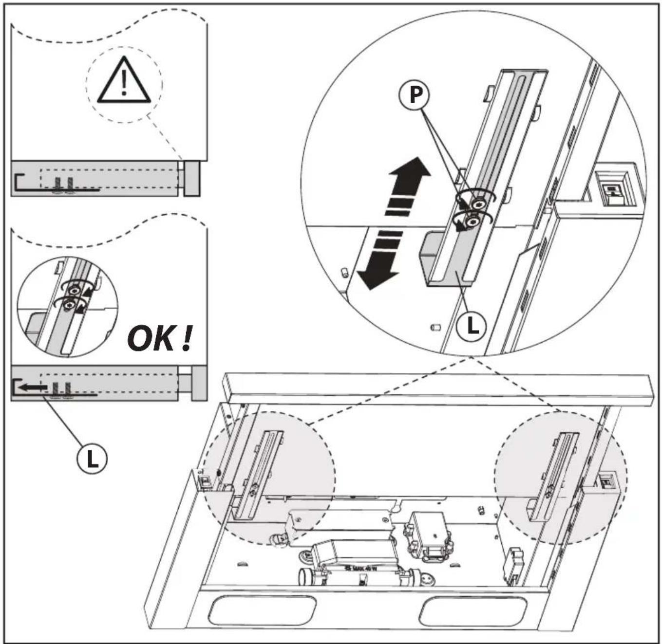
Fig.7
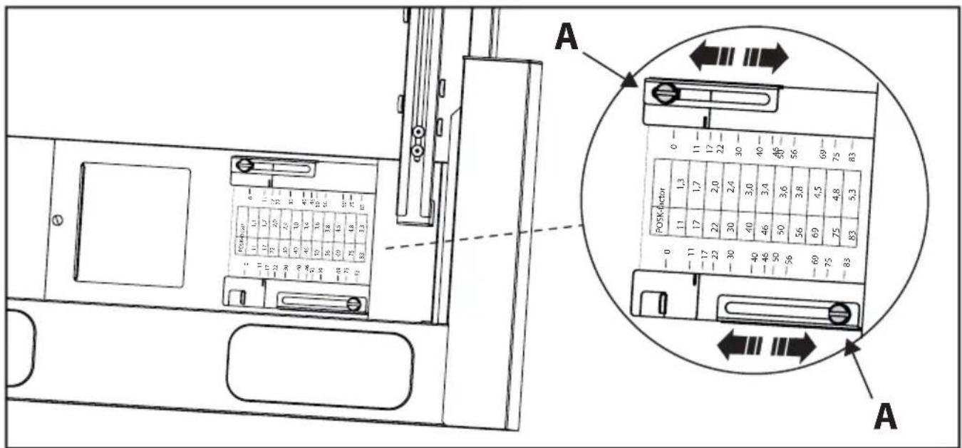
Fig.8
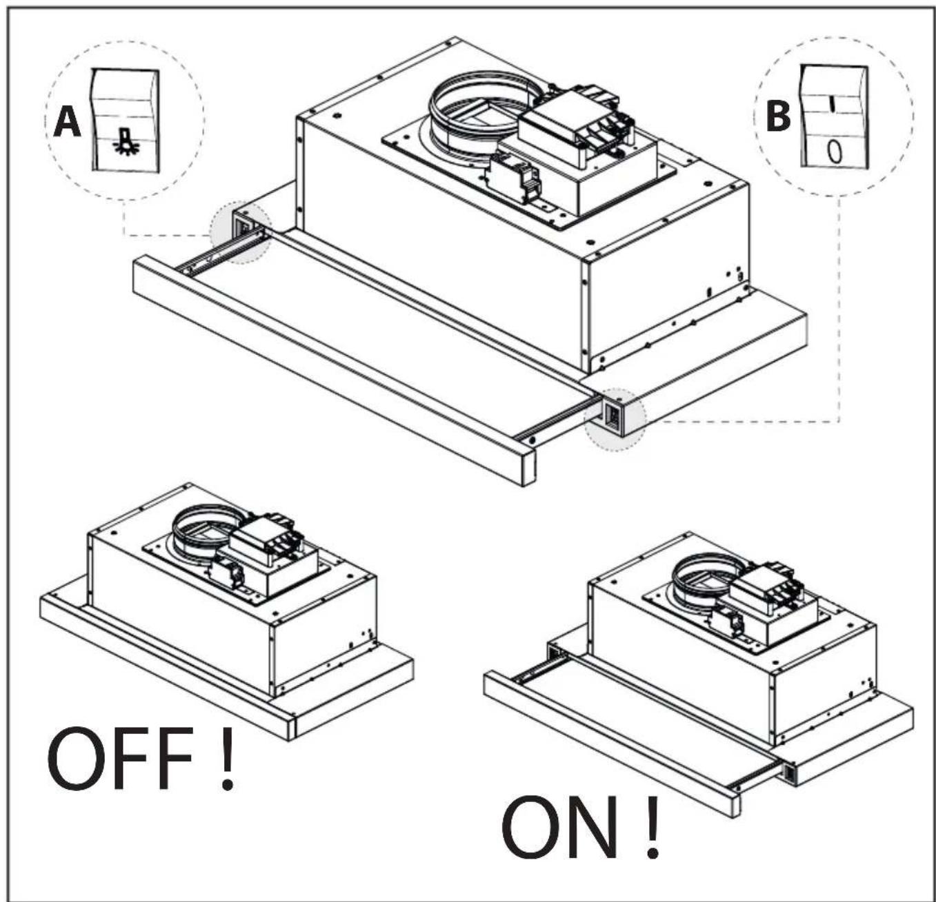
Fig.9
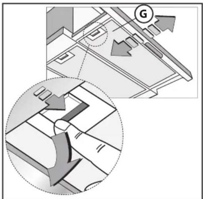
Fig.10
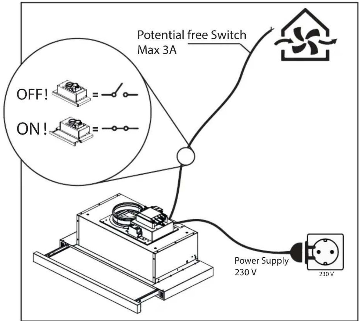
Fig.11
- EN - Connect the power plug to the mains. The potential-free relay can be connected to e.g. central ventilation system, to activate the boost function when using the hood. NOTE: Do not connect the potential-free relay to the mains.
Fig.12 - Adjustment Diagram, measure valve pressure
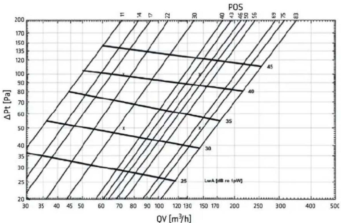
Fig.13 - Sizing diagram, pressure in ventilation duct
Extra page for adjusting the dampes

bar
| POS | K-factor | | --- | --- | | -11 | 1.3 | | -17 | 1.7 | | -22 | 2.0 | | -30 | 2.4 | | -40 | 3.0 | | -46 | 3.4 | | -50 | 3.6 | | -56 | 3.8 | | -69 | 4.5 | | -75 | 4.8 | | -83 | 5.3 | The chart displays a bar chart with two sets of bars labeled 'POS' and 'K-factor', each representing a different POS value, and the right panel shows a shaded rectangular area labeled 'A' with an open circle at the top. The label 'C' appears in the left panel.GENERAL
Carefully read the following important information regarding installation safety and maintenance. Keep this information booklet accessible for further consultations.
SAFETY PRECAUTION
- Take care when the cooker hood is operating simultaneously with an open fireplace or burner that depend on the air in the environment and are supplied by other than electrical energy, as the cooker hood removes the air from the environment which a burner or fireplace need for combustion. The negative pressure in the environment must not exceed 4Pa (4x10⁻⁵ bar). Provide adequate ventilation in the environment for a safe operation of the cooker hood. Follow the local laws applicable for external air evacuation.
Before connecting the model to the electricity network:
- Control the data plate (positioned inside the appliance) to ascertain that the voltage and power correspond to the network and the socket is suitable. If in doubt ask a qualified electrician. - If the power supply cable is damaged, it must be replaced with another cable or a special assembly, which may be obtained direct from the manufacturer or from the Technical Assistance Centre.
2. Warning!
In certain circumstances electrical appliances may be a danger hazard.
A) Do not check the status of the filters while the cooker hood is operating.
B) Do not touch bulbs or adjacent areas, during or straight after prolonged use of the lighting installation.
C) Flamè cooking is prohibited underneath the cooker hood.
D) Avoid free flame, as it is damaging for the filters and a fire hazard.
E) Constantly check food frying to avoid that the overheated oil may become a fire hazard.
F) Disconnect the electrical plug prior to any maintenance. G) This appliance can be used by children aged from 8 years and above and persons with reduced physical, sensory or mental capabilities or lack of experience and knowledge if they have been given supervision or instruction concerning use of the appliance in a safe way and understand the hazards involved. Children shall not play with the appliance. Cleaning and user maintenance shall not be made by children without supervision.
H) Young children should be supervised to ensure they do not play with the appliance.
I) There shall be adequate ventilation of the room when the rangehood is used at the same time as appliances burning gas or other fuels.
L) There is a risk of fire if cleaning is not carried out in accordance with the instructions.
INSTALLATION INSTRUCTIONS
- Assembly and electrical connections must be carried out by specialised personnel.
- Wear protective gloves before proceeding with the installa-
tion.
•ElectricConnection:
This is a class I, appliance and must therefore be connected to an efficient earthing system.
- The appliance must be connected to the electricity supply as follows:
BROWN = L line
BLUE = N neutral
YELLOW/GREEN = Earth.
The neutral wire must be connected to the terminal with the N symbol while the YELLOW/GREEN, wire must be connected to the terminal by the earth symbol ⏻
When connecting the appliance to the electricity supply, make sure that the mains socket has an earth connection. After fitting the ducted cooker hood, make sure that the electrical plug is in a position where it can be accessed easily. If the appliance is connected directly to the electricity supply, an omnipolar switch with a minimum contact opening of 3 mm must be placed in between the two; its size must be suitable for the load required and it must comply with current legislation.
- If the cooker hood is installed above a glass ceramic or induction hob, the minimum distance between the hob and the hood is 45cm . For gas stoves the minimum distance is 65cm . If a connection tube composed of two parts is used, the upper part must be placed outside the lower part. Do not connect the cooker hood exhaust to the same conductor used to circulate hot air or for evacuating fumes from other appliances generated by other than an electrical source. Before proceeding with the assembly operations, remove the anti-grease filter(s) (Fig.10) so that the unit is easier to handle.
- In the case of assembly of the appliance in the suction version prepare the hole for evacuation of the air.
- We recommend the use of an air exhaust tube which has the same diameter as the air exhaust outlet hole. If a pipe with a smaller diameter is used, the efficiency of the product may be reduced and its operation may become noisier.
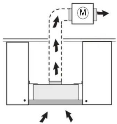
- If your appliance has been designed for use in habitations supplied with a centralised suction device perform the following operations:
- The switch controls opening and closure of a valve using a electrical motor. By placing the switch in the ON position and telescope pull-out, the valve opens allowing suction of the stale air. By placing the switch in the OFF position or close the pull-out, the valve closes.
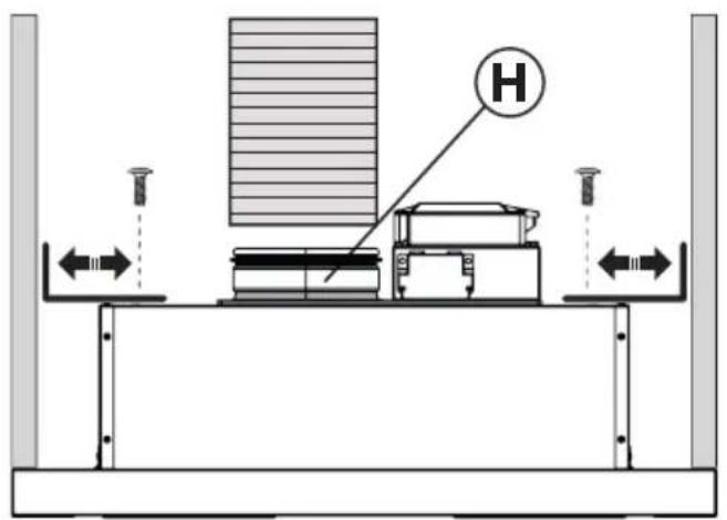
Before installing the cooker hood: assembly the electrovalve kit K as shown in fig.2 - fig.6.
The electrovalve kit K can also be turned at 180°.
•Installation:
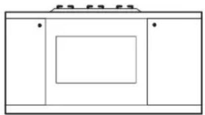
Depending on the version of the appliance you have, proceed with the installation of type "A" (Fig.3) or type "B" (Fig.4):
•Fixing the hood to the lower part of the wall cabinet:
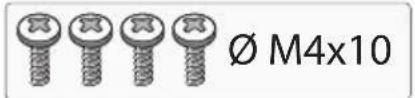
Type "A": This type of appliance must be fitted inside a cabinet or inside another type of support structure. To fix it in place, use 4 screws which are suitable for the type of cabinet, making holes in accordance with the diagram shown in Fig.1.
Type "B": For this type of hood make sure the thickness of the cabinet falls within the range of values listed in (Fig.4). Fit the cooker hood in the cabinet (Fig.4) and make sure the springs are fixed in place well. Fix the cooker hood to the cabinet securely by using a screwdriver to tighten the screws until the appliance is flush with the cabinet (Fig.5).
To fit the appliance correctly, align the front panel of the cooker hood with the cabinet door and adjust spacer L using screws P (Fig.7), then ensure the appliance meets the cabinet at the rear.
• Extraction through an outside wall:
The appliance expels the fumes through an outside wall or a duct. It is necessary to buy a telescopic pipe in accordance with the standards in use (inflammable) and connect it to flange H (Fig.3 - Fig.4).
- Adjusting the damper for proper extraction (Fig.8):
The basic ventilation has 12 setting options to which there are 12 corresponding forced settings.
BEWARE: The adjustment is done with closed valve. Remove the grease filter and loosen the screws (A), adjust the valve as needed (see the overview below). Tighten the screw and reinstall the grease filter (see extra page).
USE AND MAINTENANCE
- We recommend that the cooker hood is switched on before any food is cooked. We also recommend that the appliance is left running for 15 minutes after the food is cooked, in order to thoroughly eliminate all contaminated air. The effective performance of the cooker hood depends on constant maintenance; the anti-grease filter and the active carbon filter both require special attention.
- The anti-grease filter is responsible retaining the grease particles suspended in the air, therefore it is subject to clogging with variable frequency according to the use of the appliance.
- To prevent the danger of possible fires, at least every 2 months one must wash the anti-grease filters by hand using non-abrasive neutral liquid detergents or in the dishwasher at low temperatures and on short cycles.
- After a few washes, colour alterations may occur. This does not give the right to claim their replacement.
- Clean the hood frequently, both internally and externally, using a cloth dampened with denatured alcohol or neutral liquid detergents that are non abrasive.
- The lighting .system is designed for use during cooking and not for the prolonged general lighting of the room. The prolonged use of the lighting system significantly decreases the average duration of the bulbs.
- If the appliance is equipped with courtesy lights it is possible to use them for general room lighting for a prolonged amount of time.
- Attention: the non compliance with the hood clean-
ing warnings and with the replacement and cleaning of the filters entails risk of fires. One therefore recommends keeping to the suggested instructions.
• Control (Fig.9)
A. Press ON / OFF light
B. Valve opening / Valve closing
- Replacing the lamps
Only use lamps of the same type and wattage installed on the device.
THE MANUFACTURER DECLINES ALL RESPONSIBILITY FOR EVENTUAL DAMAGES CAUSED BY BREACHING THE ABOVE WARNINGS.
DANSK

GENERELLE OPLYSNINGER
GUL/GR∅NN = Jording.
Den nøytrale tråden må koples til pluggen med symbolet N mens den GR∅NN/GULE, tråden måkoples til pluggen nær jordingssymbolet
- Extra page for adjusting the dampes
- GENERAL
- SAFETY PRECAUTION
- Before connecting the model to the electricity network:
- Warning!
- INSTALLATION INSTRUCTIONS
- tion.
- •ElectricConnection:
- •Installation:
- • Extraction through an outside wall:
- - Adjusting the damper for proper extraction (Fig.8):
- USE AND MAINTENANCE
- - Clean the hood frequently, both internally and externally, using a cloth dampened with denatured alcohol or neutral liquid detergents that are non abrasive.
- DANSK
- GENERELLE OPLYSNINGER
Brand : Thermex
Model : Central Gemini IV
Category : Range hood