
TX II Loft - Range hood Thermex - Free user manual and instructions
Find the device manual for free TX II Loft Thermex in PDF.


| Product Type | Range Hood Motor Unit |
| Brand | Thermex |
| Model | TX II Loft |
| Voltage | 230 V ~ 50 Hz |
| Maximum Load on Connected Device | 10 kW (<25 A per phase) |
| Maximum Remote Range | 400 m (line of sight) |
| Exhaust Connection | Use original exhaust dimension; reducing it decreases performance and increases sound level |
| Reversible Vent | Yes |
| Condensate Box | Included |
| Motor Box | Included |
| Blind Plate | Included for covering unused opening |
| Spacer with Valve | Included to ensure valve opens freely |
| Vibration Damping Surfaces | Recommended for placement |
| Pipe Insulation | Required in unheated rooms to prevent condensation |
| Grounding | Mandatory |
| Safety Standard | DS/EN 60335-1 |
| Installation Requirement | Must be performed by a skilled electrician |
| Warranty Coverage | Only for private household use; warranty void for other purposes |
| Disposal | Do not dispose as household waste; take to collection center for recycling electrical equipment |
Frequently Asked Questions - TX II Loft Thermex
User questions about TX II Loft Thermex
0 question about this device. Answer the ones you know or ask your own.
Ask a new question about this device
Download the instructions for your Range hood in PDF format for free! Find your manual TX II Loft - Thermex and take your electronic device back in hand. On this page are published all the documents necessary for the use of your device. TX II Loft by Thermex.
USER MANUAL TX II Loft Thermex
natural_image
Three symbolic icons: a person reading, a book with gears and a box, and a rectangular block with double-headed arrows indicating measurement or dimension (no text or symbols present)THERMEX SCANDINAVIA A/S

www.thermex.dk

THERMEX SCANDINAVIA AS

www.thermex.no

THERMEX SCANDINAVIA AB

www.thermex.se

THERMEX SCANDINAVIA S.L.U.

www.thermex.es

THERMEX SCANDINAVIA A/S

www.thermex.fi


natural_image
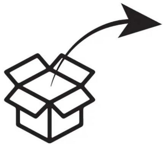
Simple line drawing of an open box with a curved arrow pointing upward (no text or symbols)
natural_image
Simple line drawing of an open book with gears and a small box, no text or symbols present.× 1
natural_image
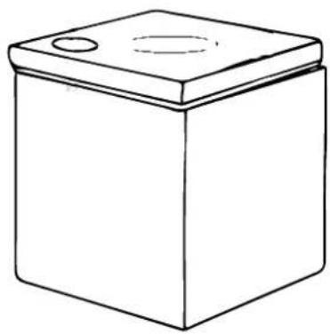
Simple line drawing of a rectangular box with a lid and two circular holes on top (no text or symbols)× 1
natural_image
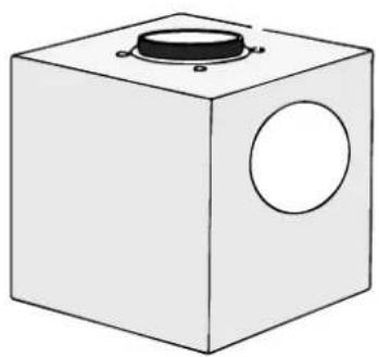
Simple line drawing of a cube with a circular hole on top and a hole on the side (no text or symbols)x 1
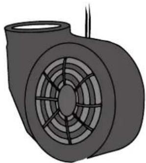
natural_image
Illustration of a mechanical component with concentric circular patterns and a protruding rod (no text or symbols)x 1
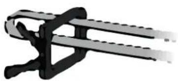
natural_image
Mechanical clamp or bracket component (no visible text or symbols)x 2
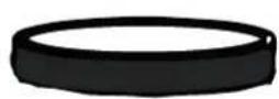
x 1
Indhold
| Dansk | 6 |
| Norsk | 12 |
| Svenska | 18 |
| Suomi | 24 |
| Espanöl | 30 |
| English | 36 |
6 THERMEX TX II motor M 225191200215032021
INDHOLD
Generel adversel 7
Montering 8
Elinstallation 10
Service 11
GENEREL ADVARSEL
1
natural_image
Simple line drawing of a box with a lid and an arrow pointing to its bottom (no text or symbols)natural_image
3D diagram of a mechanical component with a cylindrical housing and a blue arrow indicating direction (no text or symbols)natural_image
Simple line drawing of a cube with an arrow indicating rotation and a magnified inset showing a tool (no text or symbols)natural_image
Diagram showing a cube being lifted by a downward arrow, with no text or symbols present.natural_image
Diagram of a mechanical press or stamping device with a square base and circular component, showing a downward arrow indicating compression (no text or symbols present)natural_image
Simple line drawing of a mechanical component with a circular top and arrow indicating direction (no text or symbols)natural_image
Diagram of a roof structure with pipes and a valve, no text or symbols presentnatural_image
Diagram showing a pipe with internal flow lines and a shaded rectangular area, labeled with number 12 (no text or symbols within the diagram itself)1
natural_image
Simple line drawing of a box with a lid and an arrow pointing to its bottom (no text or symbols)natural_image
3D diagram of a mechanical component with a rotating wheel and housing, showing motion direction (no text or symbols)Ta motoren ut av motorboksen.
4
natural_image
Simple line drawing of a cube with an arrow indicating rotation and a magnified inset showing a tool (no text or symbols)Skjær det merkede hullet på siden av kondens kassen. Bruk med fordel det runde stykke isopor som er skåret ut til å lukke det gamle hullet i kondens boksen..
6
natural_image
Diagram showing a cube being lifted by a downward arrow, with no text or symbols present.natural_image
Diagram of a mechanical press or stamping device with a square base and circular component, showing a downward arrow indicating compression (no text or symbols present)natural_image
Simple line drawing of a mechanical component with a circular top and arrow indicating direction (no text or symbols)natural_image
Diagram of a roof structure with pipes and a valve, no text or symbols presentnatural_image
Diagram showing a curved pipe with internal parallel lines and a shaded rectangular area, labeled with number 12 (no text or symbols within the diagram itself)1
natural_image
Simple line drawing of a box with a lid and an arrow pointing to its bottom (no text or symbols)natural_image
3D diagram of a mechanical component with a cylindrical housing and a blue arrow indicating direction (no text or symbols)Ta ut motorn ur motorhuset.
4
natural_image
Simple line drawing of a cube with an arrow indicating rotation and a magnified inset showing a tool (no text or symbols)natural_image
Diagram showing a cube being lifted by a downward arrow, with no text or symbols present.natural_image
Diagram of a mechanical press or stamping device with a square base and circular component, showing a downward arrow indicating compression (no text or symbols present)natural_image
Simple line drawing of a mechanical component with a circular top and arrow indicating direction (no text or symbols)natural_image
Diagram of a roof structure with pipes and a valve, no text or symbols presentnatural_image
Diagram showing a curved pipe with internal parallel lines and a shaded rectangular area, labeled with number 12 (no text or symbols within the diagram itself)1
natural_image
Simple line drawing of a box with a lid and an arrow indicating upward motion (no text or symbols)natural_image
3D diagram of a mechanical component with a cylindrical housing and a rotating wheel, showing motion direction (no text or symbols)natural_image
Simple line drawing of a cube with an arrow indicating rotation and a magnified inset showing a tool (no text or symbols)natural_image
Diagram showing a cube being lifted by a downward arrow, with no text or symbols present.natural_image
Diagram of a mechanical press or stamping device with a square base and circular component, showing a downward arrow indicating compression (no text or symbols present)natural_image
Simple line drawing of a mechanical component with a circular top and arrow indicating direction (no text or symbols)natural_image
Diagram of a roof structure with pipes and a valve, no text or symbols presentnatural_image
Diagram showing a pipe with internal flow lines and a shaded rectangular area, labeled with number 12 (no text or symbols within the diagram itself)1
natural_image
Simple line drawing of a box with a lid and an arrow pointing to its bottom (no text or symbols)natural_image
3D diagram of a mechanical component with a cylindrical housing and a blue arrow indicating direction (no text or symbols)natural_image
Simple line drawing of a cube with an arrow indicating rotation and a magnified inset showing a tool (no text or symbols)natural_image
Simple line drawing of a box with two circular holes and a downward arrow indicating compression (no text or symbols)natural_image
Diagram of a mechanical press or stamping device with a square base and circular component, showing a downward arrow indicating compression (no text or symbols present)natural_image
Simple line drawing of a mechanical component with a cylindrical top and a blue arrow indicating direction (no text or symbols)natural_image
Diagram of a roof structure with pipes and a valve, no text or symbols presentnatural_image
Diagram showing a pipe with internal flow lines and a shaded rectangular area, labeled with number 12 (no text or symbols within the diagram itself)Electrical installation 40
Service 41
WARNINGS
- The product is designed and manufactured according to DS/EN 60335-1.
- This product is only for use in private householdings, if used for other purposes the warranty will be repealed.
- Installation must be performed by a skilled electrician in accordance with the specifications given by Thermex Scandinavia A/S (Thermex) and legislation in force.
- Thermex disclaims all responsibility with regards to damages caused by wrong installation, mounting or use.
BEFORE MOUNTING/COMMISSIONING
- Inspect the product for transport damages, flaws and defects immediately after the receipt.
- Transport damages must be filed to the haulage contractor and Thermex immediately after the receipt.
- Flaws and defects must be filed to Thermex within 8 days after the receipt, and not later than mounting/commissioning.
INSTALLATION
- The device is designed to operate at 230Volts ±10%\~50 Hz.
• The device must always be grounded.
• Maximum range between receiver and transmitter is 400 m (line of sight). - Maximum load on the connected device is 10 kW (<25 A per phase).
INSTALLATION
The motor is sold for mounting with a Thermex hood. Always follow these instructions and the installation instructions for the hood carefully to ensure that the product is installed correctly.
NOTE:
The motor has the option of reversible vent. If it is not desired, turn to point 8 in the installation instructions.
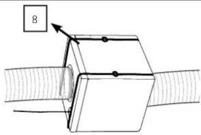
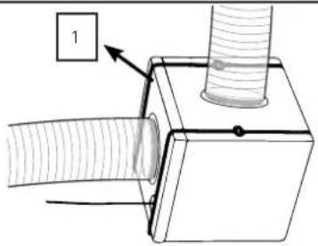
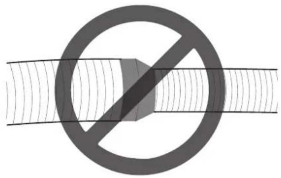
NOTE: Always use the original exhaust dimension. By reducing the exhaust dimensions, the performance decreases and the sound level increases.
1
natural_image
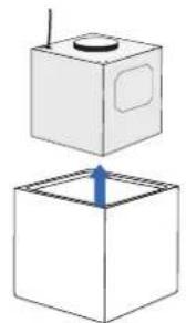
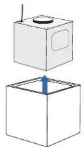
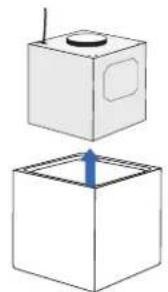
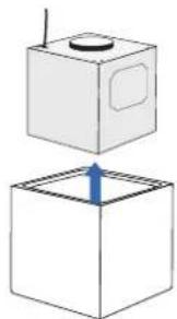
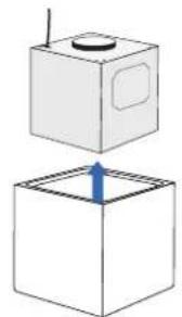
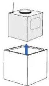
Simple line drawing of a box with a lid and an arrow pointing upward (no text or symbols)Take the motor box out of the condenser box.
2
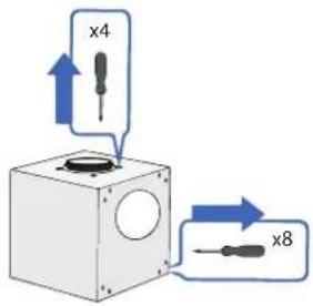
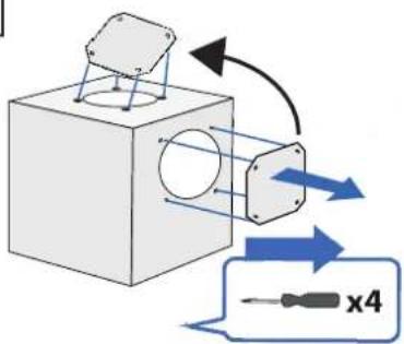
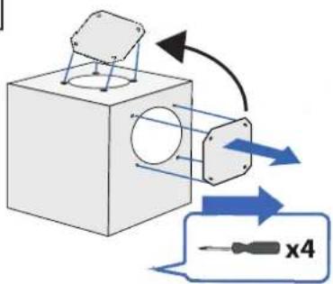
Remove the side of the motor box and un-screw the motor.
3
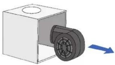
natural_image
3D diagram of a mechanical component with a rotating wheel and housing, showing motion direction (no text or symbols)Take the motor out of the motor box.
4
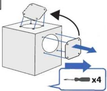
Remove the blind plate on the side of the motor box and mount it in the opening where the motor was located. Note: The plate is tightened with nuts on the inside of the motor box.
5
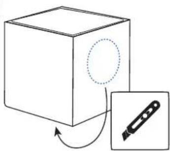
natural_image
Simple line drawing of a cube with an arrow indicating rotation and a magnified inset showing a tool (no text or symbols)Cut the marked hole in the side of the condensate box. Use the round piece of flamingo to insulate the now open hole in the box.
6
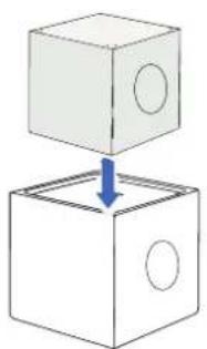
natural_image
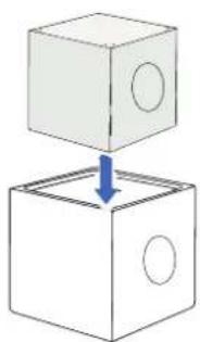
Simple line drawing of a box with two circular holes and a downward arrow indicating compression (no text or symbols)Put the motor box back in the condenser box so that the openings in the motor box and the condenser box match up..
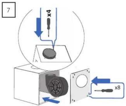
The motor is mounted in the motor box, inside the condenser box, fastened with screws. The side of the motor box is then reassembled.
natural_image
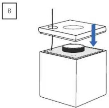
Diagram of a mechanical press or stamping device with a square base and circular component, showing a downward arrow indicating compression (no text or symbols present)Put the lid on the condenser box and pull the power cable for the motor out through the small hole in the lid.
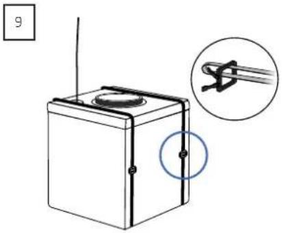
Fit the supplied strips around the condensate box.
natural_image
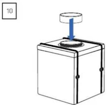
Simple line drawing of a mechanical component with a circular top and arrow indicating direction (no text or symbols)Mount the spacer on the flange with the valve. This is done to ensure that the valve can open freely when the exhaust is mounted.
natural_image
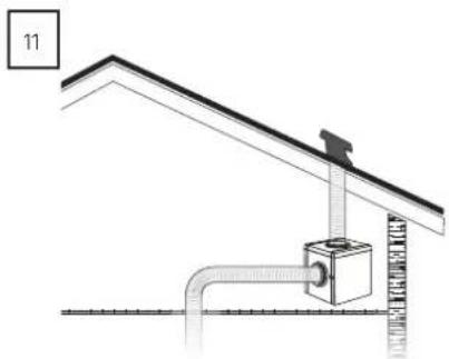
Diagram of a roof structure with pipes and a valve, no text or symbols presentPosition the engine as desired. Install exhaust from the hood to the engine, and from the engine to the outdoors.
NOTE: If necessary, place the motor on vibration-damping surfaces.
natural_image
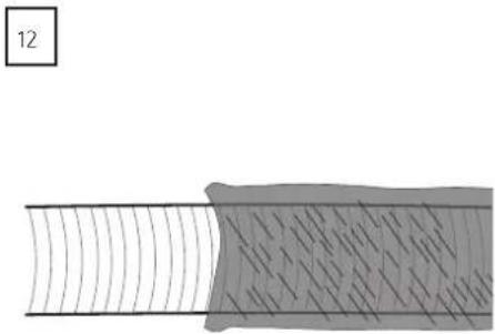
Diagram showing a pipe with internal flow lines and a shaded rectangular area, labeled with number 12 (no text or symbols within the diagram itself)Pipes and hoses must be insulated in unheated rooms so that no condensation forms.
WARNING!: Damage to the device caused by condensation is not covered by the right of complaint.
ELECTRICAL INSTALLATION
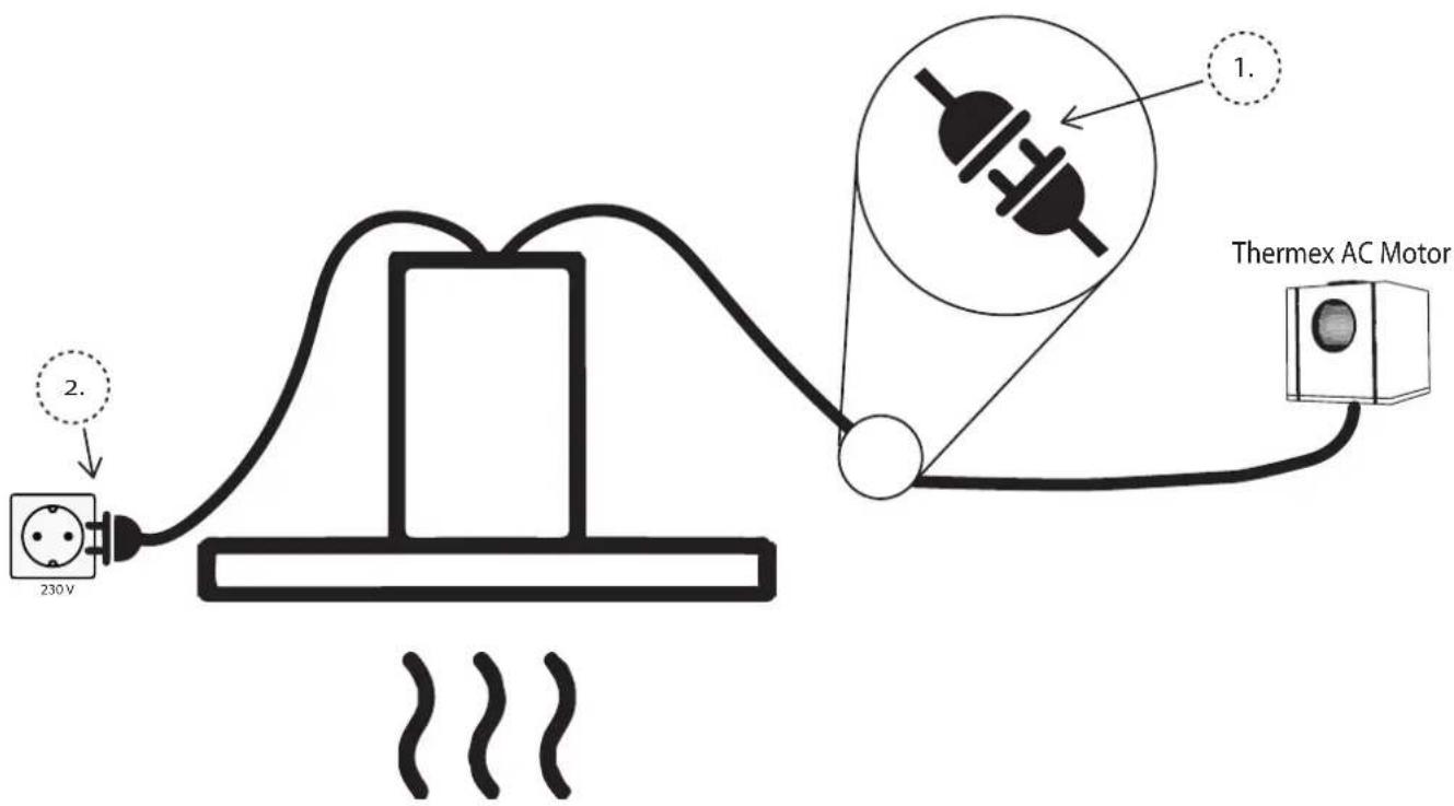
SERVICE
Before reporting service on your Thermex product, it is important that you read the installation and/or user instructions carefully. It ensures that Thermex can provide you the best possible assistance.
Service department at Thermex can be contacted in preparation to:
• Technical support for installation and installation of your produkt.
- Clarification of functionalities in your product.
• Service Request during the warranty on your product.
Before a service request during the warranty always try to disconnect the power to the product for about 5 min. Then plug the power back on to see if the problem is corrected.
If the problem is not corrected, disconnect the power supply to the product for one hour. If the product is still not functioning properly, and the troubleshooting charts are reviewed, contact the service department.
NOTE: For inquiries within the warranty, you will be asked for proof of your purchase in the form of a sales receipt. Therefore, always store your sales receipt
Before the request for service within the warranty, it is important to have all the necessary information ready:
- Error Description
- Model
• The type and serial number of the product
• Information of purchase
MILJ∅HENSYN
EMBALLAGE
SKROTNING AF PRODUKTET

The packaging must be disposed of in accordance with local regulations on waste management.
SCRAPPING OF THE PRODUCT

The symbol _1 on the product or accompanying documentation indicates that this product may not be disposed of as household waste but must be delivered to the nearest collection center for the recycling of electrical and electronic equipment.
THERMEX SCANDINAVIA A/S
Brand : Thermex
Model : TX II Loft
Category : Range hood