
Reading - Range hood Thermex - Free user manual and instructions
Find the device manual for free Reading Thermex in PDF.


| Type of product | Range hood |
| Brand | Thermex |
| Model | Reading |
| Width | 900 mm |
| Depth | 500 mm |
| Height | 600 mm |
| Weight | 15 kg |
| Power supply | 220-240 V, 50 Hz |
| Maximum extraction rate | 600 m³/h |
| Noise level | 60 dB (A) |
| Number of speeds | 3 |
| Lighting | LED, 2 x 3 W |
| Filter type | Aluminum grease filters |
| Duct diameter | 150 mm |
| Control type | Touch panel |
| Energy class | A |
| Installation | Wall-mounted |
| Material | Stainless steel |
| Maintenance | Clean grease filters monthly |
| Safety features | Auto-off timer, safety cut-off |
| Spare parts | Grease filters, LED lamps |
| Repair score | 7/10 |
Frequently Asked Questions - Reading Thermex
User questions about Reading Thermex
0 question about this device. Answer the ones you know or ask your own.
Ask a new question about this device
Download the instructions for your Range hood in PDF format for free! Find your manual Reading - Thermex and take your electronic device back in hand. On this page are published all the documents necessary for the use of your device. Reading by Thermex.
USER MANUAL Reading Thermex
natural_image
Diagram showing a room with a patterned wall, a circular object with dashed lines, and a shaded ground area (no text or symbols)natural_image
Diagram showing a curved structure with a magnified inset of a water droplet on a surface, labeled '5' (no text or symbols on the diagram itself)natural_image
Diagram of a mechanical device with a blue arrow indicating direction, no visible text or symbolsnatural_image
Diagram of a mechanical device with a blue arrow pointing to a component, set against a grid background (no text or symbols)natural_image
Diagram showing a cylindrical object being inserted into a base on a workpiece, with an inset magnified view highlighting the process (no text or symbols present)natural_image
Technical line drawing of a mechanical assembly with a base and support bracket (no text or symbols)natural_image
3D diagram of a box with a screw and a magnified inset showing a cross-section (no text or symbols)natural_image
Diagram showing a device with a blue arrow pointing to it, placed on a grid background (no text or symbols)natural_image
Simple line drawing of a room with a window, a circular object, and a dark spot on the floor (no text or symbols)natural_image
Diagram of a mechanical device with a blue arrow pointing to a component, no visible text or symbolsnatural_image
Diagram of a mechanical device with a blue arrow indicating direction, no visible text or symbolsnatural_image
Diagram showing a mechanical setup with a cylindrical component inserted into a base, with an inset magnified view of the component (no text or symbols present)Monter avtrekket på viften.
MERK: Dette gjelder kun dersom det ønskes avtrekk til friluft.
MONTERING AV KANAL MED AVTREKK TIL FRILUFT
natural_image
Simple line drawing of a 3D object with a rectangular block and a curved surface, set on a grid background (no text or symbols)Skru braketten fast til veggen.
Sett kanalen på viften.
natural_image
Pure technical diagram showing a mechanical assembly with no text, numbers, or symbolsSkru braketten og dekkplaten fast til veggen.
4
natural_image
3D diagram of a box with a screw inside, showing a magnified inset labeled 'x2' (no text or symbols on the diagram itself)Sett kanalen på viften.
natural_image
Simple line drawing of a room with a window, a circular inset showing a CD, and a black shadow on the floor (no text or symbols)natural_image
Technical diagram showing a 3D curved surface with a magnified inset of a component detail (no text or symbols)natural_image
Diagram of a mechanical device with a blue arrow indicating direction, no visible text or symbolsnatural_image
Diagram showing a curved surface with a magnified inset of a small object, no text or symbols present.natural_image
Diagram of a device with a magnified inset showing a control panel and a blue curved line, no text or symbols present.natural_image
Technical diagram of a mechanical component with a blue arrow indicating direction, set against a grid background (no text or symbols)natural_image
Diagram showing a cylindrical object being inserted into a base, with an inset magnified view of the top section (no text or symbols)natural_image
3D geometric diagram showing a rectangular prism mounted on a curved surface, with a small rectangular object above it (no text or symbols)natural_image
3D diagram of a box with a screw inside, showing a magnified inset labeled 'x2' (no text or symbols on the main diagram)natural_image
Technical diagram showing a 3D mechanical part with a magnified inset of its cross-section, including a coordinate system labeled 'x2' (no text or symbols on the main diagram itself)natural_image
Pure technical diagram showing a mechanical assembly with no text, numbers, or symbolsnatural_image
Illustration of a box with a screw inside, placed on a grid background with an inset showing a cross-section labeled 'x2' (no text or symbols on the diagram itself)natural_image
Diagram showing a room with a framed picture and a circular object, no text or symbols presentnatural_image
Diagram of a mechanical device with a blue arrow indicating direction, no visible text or symbolsnatural_image
Diagram of a mechanical device with a blue arrow indicating direction, no visible text or symbolsnatural_image
Diagram showing a mechanical component with a magnified inset highlighting a cylindrical feature, no text or symbols present.natural_image
3D geometric diagram showing a cube, rectangular prism, and curved surface on grid background (no text or symbols)natural_image
3D diagram of a box with a screw and a magnified inset showing a cross-section (no text or symbols)natural_image
Pure technical diagram showing a mechanical assembly with no text, numbers, or symbolsnatural_image
Simple line drawing of a room with a window, a circular object, and a dark spot on the floor (no text or symbols)natural_image
Technical diagram showing a curved structural component with a magnified inset of a water droplet (no text or symbols)natural_image
Diagram of a device with a blue arrow indicating direction, showing internal components and a grid background (no text or symbols)natural_image
Diagram of a mechanical device with a blue arrow indicating direction, set against a grid background (no text or symbols)natural_image
Diagram showing a mechanical component with a magnified inset highlighting a cylindrical feature, no text or symbols present.natural_image
Technical line drawing of a mechanical assembly with a bracket and curved base (no text or symbols)natural_image
Illustration of a box with a screw inside, placed on a grid background with an inset showing a magnified view labeled 'x2' (no text or symbols on the diagram itself)Montar la chimenea encima de la campana.
natural_image
Technical diagram showing a 3D object with a magnified inset of its cross-section, alongside a mechanical part with dimension annotation (x2), no readable text or symbols present.natural_image
Isometric diagram of a wall-mounted device with a blue arrow indicating direction, set against a grid background (no text or symbols)natural_image
Simple line drawing of a mechanical assembly with a base and shaft, no text or symbols presentMontar la chimenea encima de la campana.
| Warnings | 65 |
| Included in the box | 67 |
| Dimnesional drawings | 68 |
| Installation | 69 |
| Electrical installation | 74 |
WARNINGS
- The range hood is designed and manufactured according to DS/EN 60335-1.
- This range hood is only for use in private house holdings, if used for other purposes the warranty will be repealed.
• Installation must be performed by a skilled electrician in accordance with the specifications given by Thermex Scandinavia A/S (Thermex) and legislation in force. - Thermex disclaims all responsibility in regards to damages caused by wrong installation, mounting or use.
BEFORE MOUNTING/COMMISSIONING
- Inspect the range hood for transport damages, flaws and defects immediately after the receipt.
- Transport damages must be filed to the haulage contractor and Thermex immediately after the receipt.
- Flaws and defects must be filed to Thermex within 8 days the receipt, and not later than mounting/commissioning.
MOUNTING
- The range hood is intended for working at 230 Volt ±10%\~50 HZ ±10% in referring to EN 50160.
- Connect the hood with the attached plug. NOTE: The hood MUST have earth if the plug has an earth connection.
- For models with external motor applies
that NOT to use common zero by installing the hood and engine, as this will affect the control.
- It MUST be ensured that the motor can be used with the selected range hood when using an external motor from another supplier. Otherwise the warranty no longer apply.
- Do not plug in the range hood until the mounting is complete.
- The air must not be discharged from the hood into a pipe used for extraction from devices using gas or other fuels. Such devices must have a separate vent.
- The national legislation on air emissions must be observed.
• Always use the original dimension of the vent. By reducing the dimension of the vent, the performance will be reduced and the sound level will be increased.
- The vent to the open air, must be as short as possible in order to get the greatest possible capacity of the range hood.
- The number of bends on the vent ought to be minimised, to gain the greatest possible capacity of the range hood.
- Thermex recommends to always use sound and condensation insulated vent hose at the carrying through in unheated spaces.
- Thermex recommends that there is used for a muffler to minimize the noise level when using flexible hose.
- Using the flexible hose must always ensure that this is fully extended to minimize air resistance and thereby achieve maximum absorbency.
- Different materials takes different rawlplugs and screws. Use rawlplugs and screws intended for the material the range hood is to be mounted in.
- If the instructions for the installation of screws and fittings are not followed, it may result in electrical shock.
- The minimum distance to gas stoves from the burner's edge to the underside of the hood MUST be minimum 65 cm in accordance with EN 60335-2-31.
• Thermex recommends that the space
between the lower edge of the range hood and cooker is between 50 cm and 70 cm, valid for all cabinet range hoods, islands and wall mounted range hoods.
- Always control the stated minimum distance between cooker and range hood in the manual for the cooker. If the manual for the cooker states a greater distance than what Thermex recommends the manual for the cooker MUST be followed.
- Thermex recommends that the space between cooker and range hood does not exceed 3 meters for range hoods integrated in the ceiling
INCLUDED IN THE BOX
• 1 Reading
- 1 telescoping duct
• 1 set of operating instructions
• 1 set of mounting instructions
- 4 rawlplugs
• 4 screws for installing the hood
• 1 bracket for installing the duct
• 2 screws for installing the duct
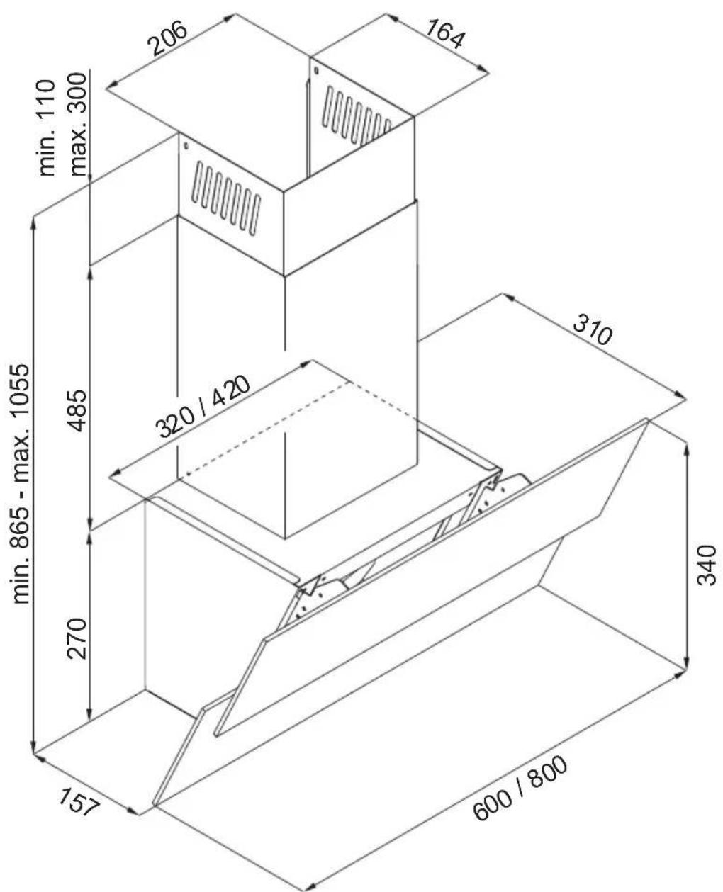
DIMENSIONAL DRAWING
other
| Dimension | Value | | --------- | ----- | | Minimum | 157 | | Maximum | 340 | | Minimum | 270 | | Maximum | 485 | | Minimum | 320 | | Maximum | 300 | | Minimum | 206 | | Maximum | 164 | | Minimum | 600 | | Maximum | 800 | | Minimum | 310 | | Maximum | 420 |INSTALLATION
The Reading is available with an internal motor. The range hood can either vent exhaust out into the open air or re-circulate the air.
Follow the instructions in this guide that match the model that you have purchased and the way in which you wish to install the exhaust outlet.
INSTALLING THE HOOD
The hood is installed on the wall using the following steps:
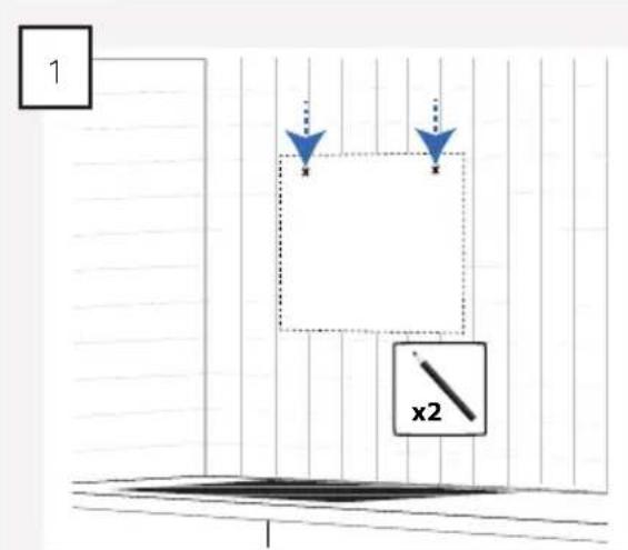
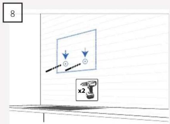
Measure out and mark the two "keyholes" on the wall.
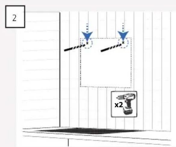
Drill the holes into the wall using a suitable drill for the type of wall.
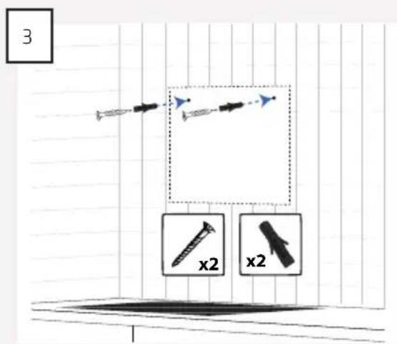
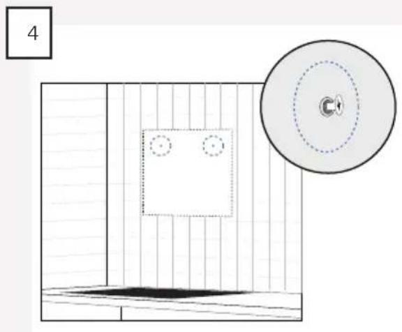
Ensure that the rawlplugs and screws are suitable for the wall material in question and insert them into the pre-drilled holes.
natural_image
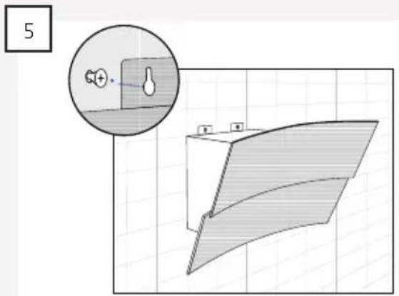
Diagram showing a room with a framed picture and a CD, no text or symbols presentNOTE: The screws must not be screwed in further than the hood can be installed.
natural_image
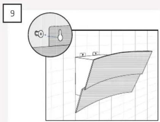
Technical diagram showing a curved panel with a magnified inset of a component (no text or symbols)Hang the hood on the screws.
natural_image
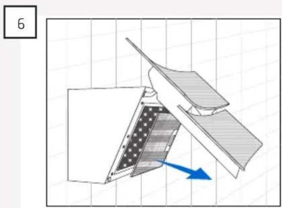
Diagram of a mechanical device with a blue arrow indicating direction, no text or symbols presentOpen the glass door and remove the filter.
Mark the position of the two lock-holes on the wall and then remove the hood from the wall once again.
Pre-drill the holes and insert the rawlplugs.
Re-hang the hood.
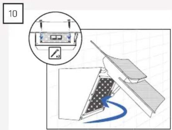
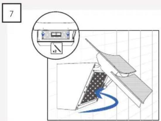
Screw the screws into the two lock-holes.
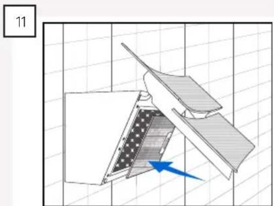
natural_image
Technical diagram of a mechanical device with a blue arrow indicating direction, no visible text or symbolsReinstal the filter in the hood and close the glass door.
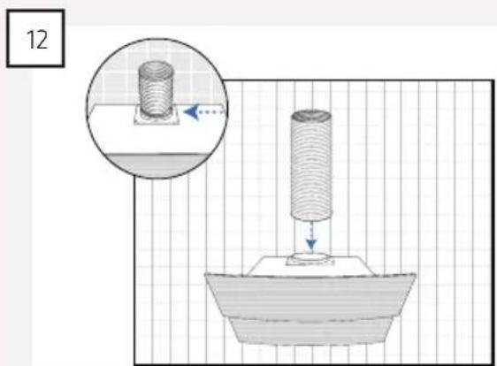
natural_image
Diagram of a mechanical press or drill setup with a cylindrical component and base, showing a magnified inset (no text or symbols)Install the exhaust outlet on the hood. NOTE: This only applies when venting into open air.
INSTALLING THE DUCT FOR OPEN-AIR VENTING
If the hood is going to be installed with exhaust venting into the open air, the duct is installed as follows:
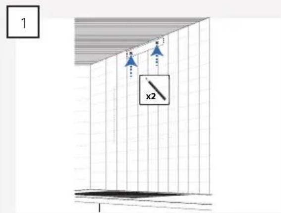
Measure the placement of the bracket and mark the position of the holes on the wall.
NOTE: The bracket must be positioned so that it matches the holes in the duct.
natural_image
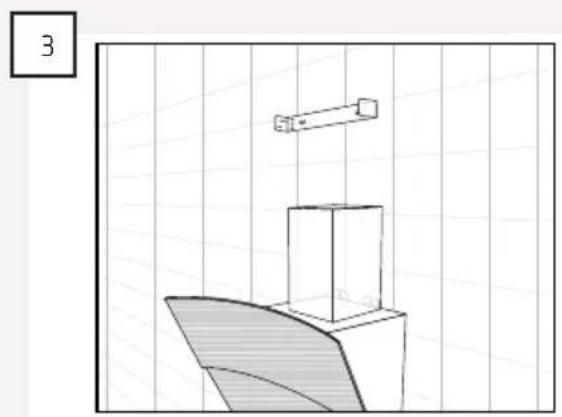
Simple line drawing of a 3D geometric shape with a rectangular prism above a curved base, set against a grid background (no text or symbols)Screw the bracket onto the wall.
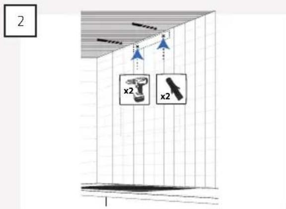
Pre-drill the holes and insert the rawlplugs.
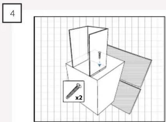
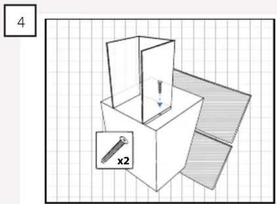
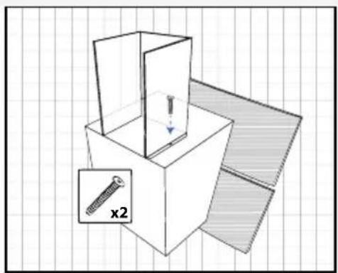
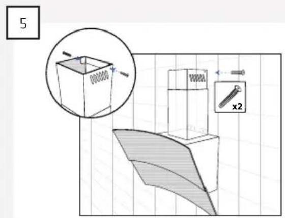
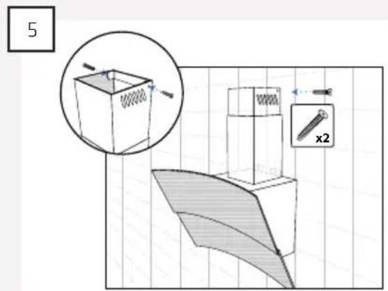
Place the duct on the hood.
NOTE: Fasten the duct with two screws.
Push the topmost section of the duct upwards and attach it to the bracket with the two self-tapping screws.
INSTALLING THE DUCT WHEN THE HOOD IS TO BE USED FOR RECIRCULATION
If the hood is going to be used for recirculation, the cover panel must be installed up to the ceiling to cover the duct.
The duct is therefore installed as follows:
1
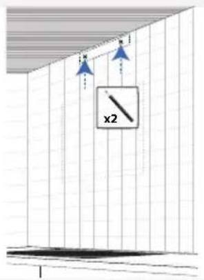
Measure the placement of the bracket and mark the position of the holes on the wall.
NOTE: The bracket must be positioned so that it matches the holes in the duct.
2
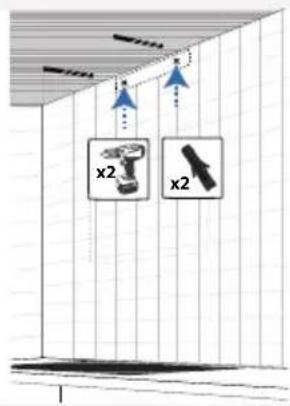
Pre-drill the holes and insert the rawlplugs.
3
natural_image
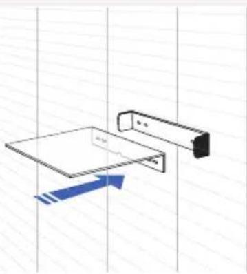
Pure technical diagram showing a mechanical assembly with no text, numbers, or symbolsScrew the bracket and cover panel onto the wall.
4
natural_image
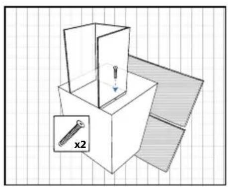
3D diagram of a box with a screw and a magnified inset showing a cross-section (no text or symbols)Place the duct on the hood.
NOTE: Fasten the duct with two screws.
Push the topmost section of the duct upwards and attach it to the bracket with the two self-tapping screws.
ELECTRICAL INSTALLATION
Connect the hood to the electrical mains socket using the installed Schuko plug.
NOTE: The hood must be grounded.
THERMEX SCANDINAVIA A/S SERVICEAFD.
Brand : Thermex
Model : Reading
Category : Range hood