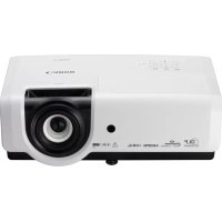
LV-7215 - Projecteur professionnel CANON - Notice d'utilisation et mode d'emploi gratuit
Retrouvez gratuitement la notice de l'appareil LV-7215 CANON au format PDF.

| Type de produit | Projecteur professionnel |
| Marque | Canon |
| Modèle | LV-7215 |
| Compatibilité support de montage | LV-CL08 (pour plafond bas) |
| Poids du kit de montage (LV-CL08) | 1.7 kg |
| Distance de projection (zoom max) | 1.0 m (40") à 7.7 m (300") |
| Distance de projection (zoom min) | 1.6 m (40") à 6.0 m (150") |
| Angle d'inclinaison | ±15° dans une rotation de 360° |
| Rotation horizontale | 360° |
| Fonctions principales | Projection d'images, zoom, mise au point, ajustement d'angle |
| Alimentation | 100-240 V AC, 50/60 Hz (standard) |
| Sécurité | Installation par professionnel recommandée ; prévention des chutes par câble de sécurité |
| Entretien | Nettoyer régulièrement les filtres à air et les lentilles |
| Température de fonctionnement | 5°C à 35°C (estimation) |
| Humidité de fonctionnement | 20% à 80% sans condensation (estimation) |
| Garantie | Consulter la notice ou le revendeur |
FOIRE AUX QUESTIONS - LV-7215 CANON
Questions des utilisateurs sur LV-7215 CANON
0 question sur cet appareil. Repondez a celles que vous connaissez ou posez la votre.
Poser une nouvelle question sur cet appareil
Téléchargez la notice de votre Projecteur professionnel au format PDF gratuitement ! Retrouvez votre notice LV-7215 - CANON et reprennez votre appareil électronique en main. Sur cette page sont publiés tous les documents nécessaires à l'utilisation de votre appareil LV-7215 de la marque CANON.
MODE D'EMPLOI LV-7215 CANON
低天井用取り付けハンガー 組立・設置説明書
LV-CL08
取付適合プロジェクター品番
LV-7215, LV-7210, LV-5210
設置は必ず専門の工事業者にご依頼ください。
この取り付けハンガーは上記の当社プロジェクター専用です。他の機器には使用できません。指定以外のものを乗せたりぶら下げたりしないでください。また、お子様などがぶら下がったりしない様ご注意ください。組立と設置は説明書にしたがい、正しく設置ください。注意事項は必ずお守りください。
設置上の注意

この取り付けハンガーを使ってプロジェクターを天井から吊り下げて設置する場合、天井部はプロジェクターと、この取り付けハンガーを支える十分な強度が必要です。設置の前にプロジェクターの質量と、この取り付けハンガーの質量を確認のうえ天井の強度を確認してください。強度不足の場合、十分な補強を行ってください。
●取り付けは必ず水平な天井に行ってください。傾いた天井には設置しないでください。
● 地震や、振動などによる横ゆれを防止する為に、設置のときワイヤーなどによりゆれ止めの措置を取ってください。
取り付けハンガーの本体総重量は 1.7kg です。
同梱品
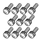
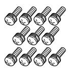
ネジ(A)…11本
ネジ(B)…1本

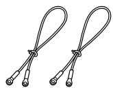
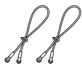
ワイヤー…2本
六角レンチ…1個

組立・設置説明書
組立と設置の手順
図1参照
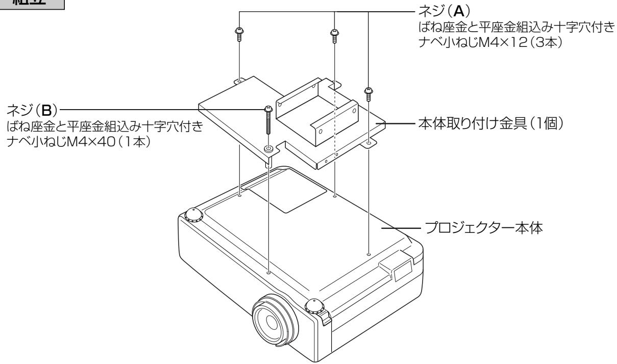
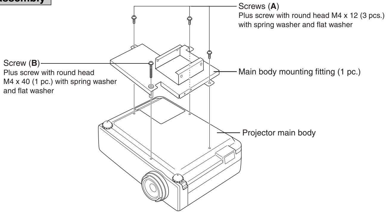
- プロジェクター本体を裏返し、本体取り付け金具にネジ(A)(B)を使用して取り付けます。 (ネジ(A)…3本) (ネジ(B)…1本)
- 落下防止ワイヤーを取り付ける。
- 天井取り付け金具を天井に取り付けます。天吊り金具取り付け寸法図を参照ください。
- 天井に固定した天吊り金具に、プロジェクターを取り付けた本体取り付け金具をスライドさせて、本体取り付け金具に同梱されているネジA(4本)を使用してしっかり固定します。 注)この時、落下しないように注意してください。一時的に吊り下げている為、固定されていません。
ケーブル配線時に、ケーブル等で吸気口や排気口をふさがないでください。
内部の温度上昇を招いて故障の原因になります。
投写位置の調整
図2参照
映像がスクリーンの中心に投写されるように合わせ、角度調整ネジを同梱の六角レンチでしっかり締めます。(角度の微調整がうまく出来ない場合は、同梱の六角レンチで角度調整ネジをゆるめ、角度微調整ネジ使用するとやりやすくなります)
図1…組立
1
text_image
組立 ネジ(A) ばね座金と平座金組込み十字穴付き ナベ小ねじM4×12(3本) ネジ(B) ばね座金と平座金組込み十字穴付き ナベ小ねじM4×40(1本) 本体取り付け金具(1個) プロジェクター本体2
text_image
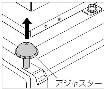
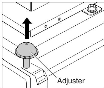
アジャスター- プロジェクター本体のアジャスターを引き出します。
text_image
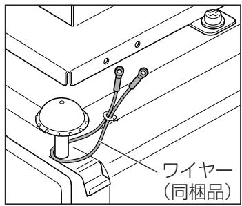
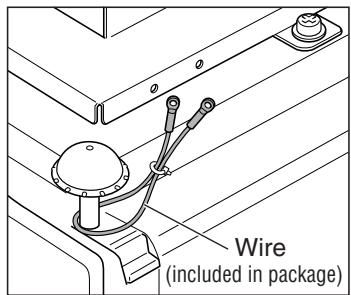
ワイヤー (同梱品)- 同梱の落下防止ワイヤーを本体のアジャスターにしっかりと掛けます。(2ヶ所)
text_image
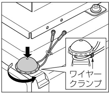
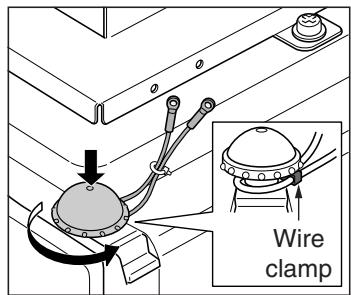
ワイヤー クランプ- ワイヤークランプを落下防止ワイヤーでしっかりと締め、本体アジャスターをおろします。
text_image
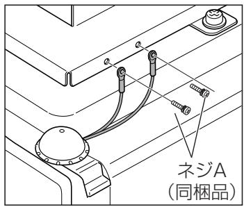
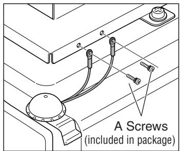
ネジA (同梱品)4.落下防止ワイヤーを同梱のネジA…2本(M4×12mm)で本体取り付け金具に取り付けます。反対側にも同様に取り付けます。

プロジェクターの落下防止対策について
※ここで説明されているプロジェクター本体の落下防止措置は必ず行ってください。
3
text_image
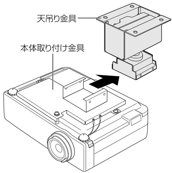
天吊り金具 本体取り付け金具4
text_image
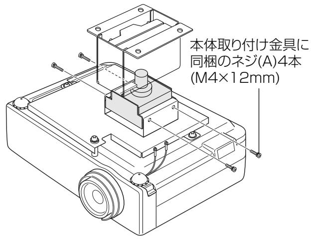
本体取り付け金具に 同梱のネジ(A)4本 (M4×12mm)図2…調整のしかた
text_image
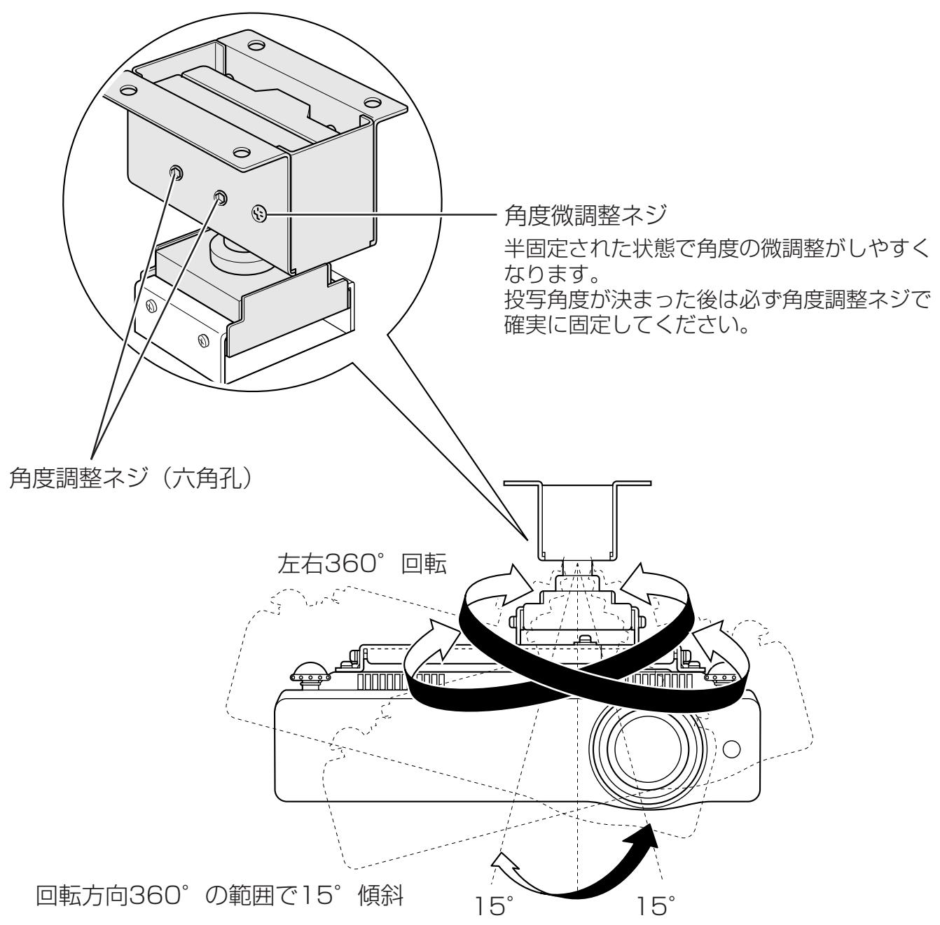
角度调整ネジ 半固定された状態で角度の微調整がしやすくなります。 投写角度が決まった後は必ず角度調整ネジで確実に固定してください。 角度調整ネジ(六角孔) 左右360° 回転 回転方向360°の範囲で15°傾斜 角度微調整ネジ 15° 15°注意

プロジェクター角度固定後、そのまま固定した状態で再角度調整を行うと、固定部の変形にともない、再固定ができない状態が発生する場合があります。再角度調整を行う場合は、角度調整ネジをゆるめて角度調整を行ってください。
調整が合わないときは再び調整しなおしてください。
調整後は、しっかり固定されていることを確認してください。
正面図
(表示寸法 单位mm)
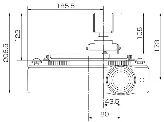
text_image
185.5 122 206.5 105 173 43.5 80側面図
(表示寸法 单位mm)
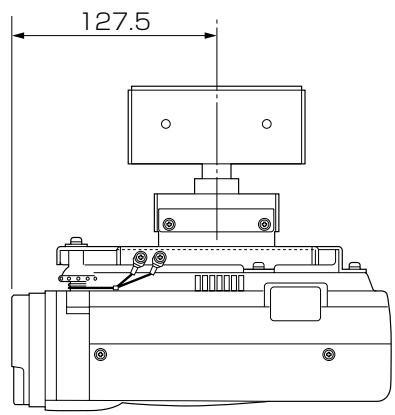
text_image
127.5天吊り金具取り付け寸法
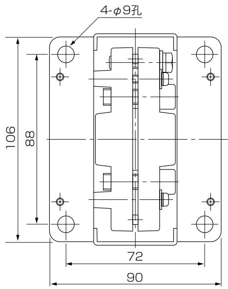
text_image
4-φ9孔 106 88 72 90■ およその投写距離
| 40型 | 60型 | 70型 | 80型 | 90型 | 100型 | 110型 | 120型 | 150型 | 200型 | 250型 | 300型 | |
| ズーム最大 | 1.0m | 1.5m | 1.8m | 2.0m | 2.3m | 2.5m | 2.8m | 3.1m | 3.8m | 5.1m | 6.4m | 7.7m |
| ズーム最小 | 1.6m | 2.4m | 2.8m | 3.2m | 3.6m | 4.0m | 4.4m | 4.8m | 6.0m | - | - | - |
※およその投写距離はレンズ設計仕様に基づく計算値です。
レンズのばらつきなどにより最大5%程度の誤差を有する場合があります。
Mounting Hanger for Low Ceilings Assembly/Installation Manual
LV-CL08
Applicable Projector Model Nos.
LV-7215, LV-7210, LV-5210
Make sure to ask a company specializing in installation work to install the hanger.
This mounting hanger is specifically for the projectors shown above. It cannot be used for any other equipment. Do not place or hang any other object on this mounting hanger. Do not let children hang on it. Assemble and install this mounting hanger correctly in accordance with this manual. Make sure to observe the cautions given here.
INSTALLATION
CAUTIONS

When displaying the projector by hanging it from the ceiling using this mounting hanger, the ceiling should have sufficient strength to support both the projector and the mounting hanger. Before installation, check the weight of the projector and the mounting hanger, then confirm the strength of the ceiling. If the ceiling does not have sufficient strength, be sure to sufficiently reinforce it.
●Make sure to install this mounting hanger from a ceiling that is level. Do not hang it from an inclined ceiling.
●In order to prevent swaying caused by earthquakes or vibration, take proper anti-swaying steps using wires, etc. during installation.
The total weight of this mounting hanger's main body is 1.7 kg.
Parts included in package
Screw (A)…11 pcs.
Screw (B)…1 pc.
Wire…2 pcs.
Hexagon wrench…1 pc.
Assembly/
Installation Manual


Assembly and installation procedure
Refer to Fig. 1.
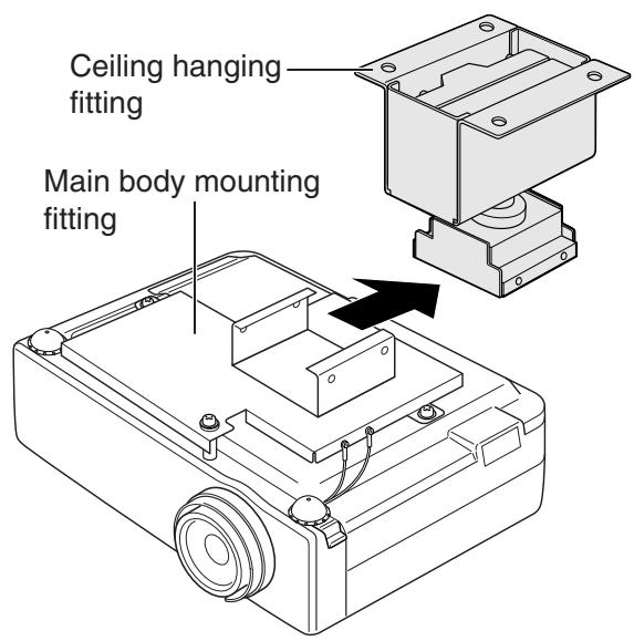
- Turn over the projector main body, and attach it to the main body mounting fitting with screws (A) and (B). (screw (A) ... 3 pcs.) (screw (B) ... 1 pc.)
- Attach the drop prevention wires.
- Attach the ceiling mounting fitting to the ceiling. Refer to the ceiling hanging fitting attachment dimensional drawing.
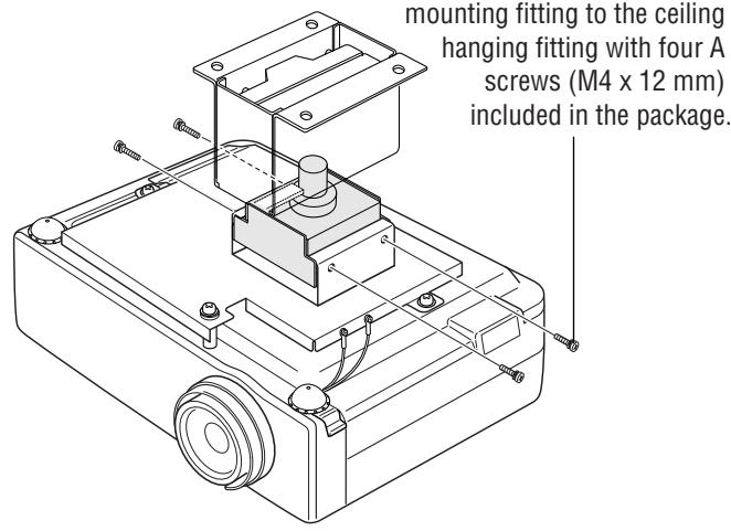
- Slide the main body mounting fitting to which the projector is attached into the ceiling hanging fitting that is attached to the ceiling. Then fix the main body mounting fitting securely to the ceiling hanging fitting with four (A) screws included in the package.
Caution : During this procedure, take care not to drop the projector. Since the projector is hung only temporarily, it is not yet secured.
When wiring, make sure not to let cables or other items block the air inlet or the exhaust port.
This may raise the inside temperature and result in a malfunction.
Adjusting the projection position
Refer to Fig. 2.
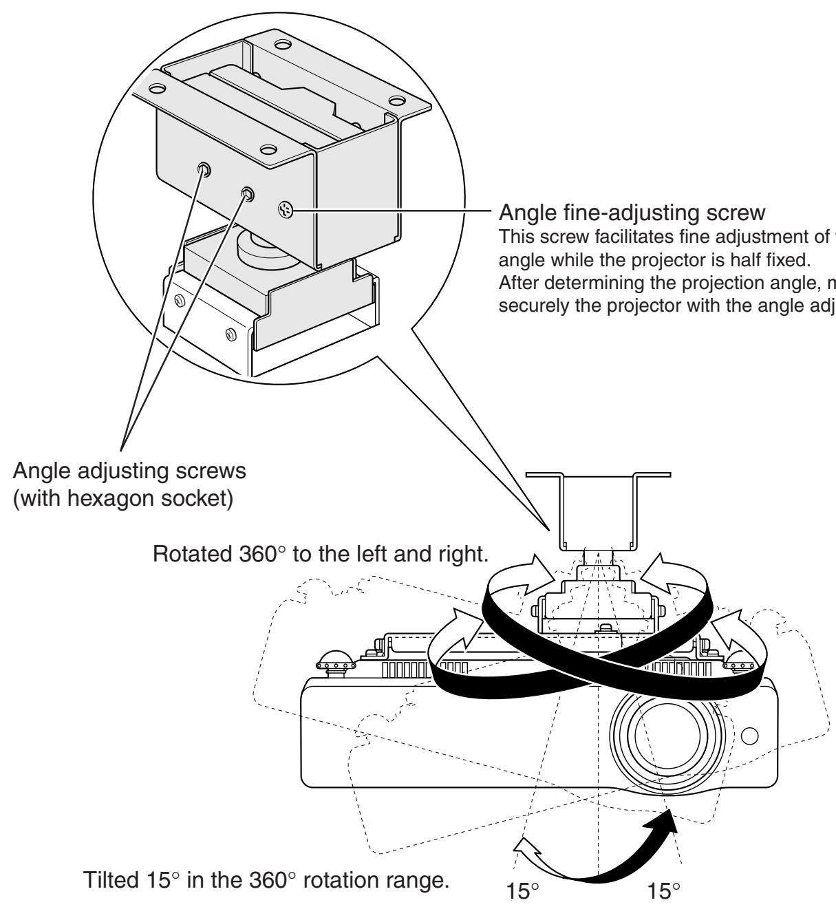
Adjust the projection position so that an image is projected in the center of the screen. Then tighten the angle adjusting screws securely using the hexagon wrench included in the package.
(If fine adjustment of the angle cannot be smoothly attained, loosen the angle adjusting screws with the hexagon wrench. Then use the angle fine-adjustment screw. This will allow smooth fine adjustment.)
Fig. 1 Assembly
1
text_image
Screw (A) Plus screw with round head M4 x 12 (3 pcs.) with spring washer and flat washer Screw (B) Plus screw with round head M4 x 40 (1 pc.) with spring washer and flat washer Main body mounting fitting (1 pc.) Projector main body2
text_image
Adjuster- Pull out the adjuster from the projector main body.
text_image
Wire (included in package)- Hang securely the drop prevention wire included in the package to the adjuster in the main body (2 positions).
text_image
Wire clamp- Tighten securely the wire clamp with the drop prevention wire, and push down the adjuster in the main body.
text_image
A Screws (included in package)- Attach the drop prevention wire to the main body mounting fitting with two A screws (M4 x 12 mm) included in the package. Attach the drop prevention wire on the opposite side in the same way.

Measures to prevent the projector from falling
* Make sure to take measures to prevent the projector main body from falling as explained here.
3
text_image
Ceiling hanging fitting Main body mounting fitting4
text_image
mounting fitting to the ceiling hanging fitting with four A screws (M4 x 12 mm) included in the package.Fig. 2 Adjustment
text_image
Angle fine-adjusting screw This screw facilitates fine adjustment of the angle while the projector is half fixed. After determining the projection angle, it is securely the projector with the angle adjusting screw. Angle adjusting screws (with hexagon socket) Rotated 360° to the left and right. Tilted 15° in the 360° rotation range. 15° 15°CAUTION

After the projector angle is fixed once, if the angle is adjusted again in the fixed status, the fixed area may be deformed and adjustment might no longer be possible. Loosen the angle adjusting screws before adjusting the angle again.
If the angle is not proper, adjust the angle again.
After adjustment, confirm that the projector is fixed securely.
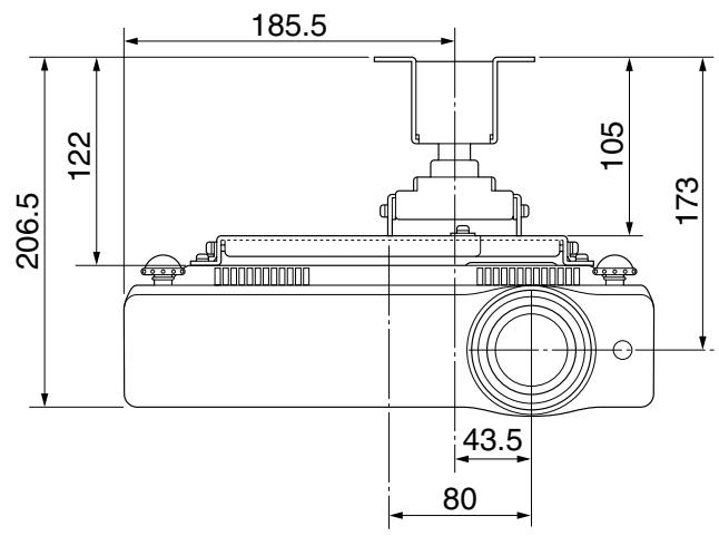
Front view
(Unit: mm)
text_image
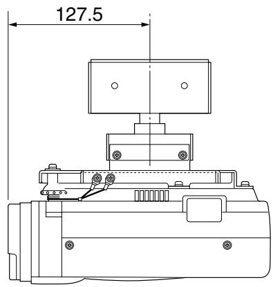
185.5 122 206.5 105 173 43.5 80Side view
(Unit: mm)
text_image
127.5Ceiling hanging fitting mounting dimensions
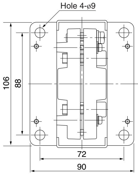
text_image
Hole 4-Ø9 106 88 72 90■ Approximate projection distance
| Screen size (diagonal)(inch) | 40 | 60 | 70 | 80 | 90 | 100 | 110 | 120 | 150 | 200 | 250 | 300 |
| Maximum zoom | 1.0m | 1.5m | 1.8m | 2.0m | 2.3m | 2.5m | 2.8m | 3.1m | 3.8m | 5.1m | 6.4m | 7.7m |
| Minimum zoom | 1.6m | 2.4m | 2.8m | 3.2m | 3.6m | 4.0m | 4.4m | 4.8m | 6.0m | — | — | — |
* Each approximate projection distance is a calculated value based on lens design specifications.
An error of approximately 5% maximum may occur due to lens quality, etc.