LV-7215 - Professional projector CANON - Free user manual and instructions
Find the device manual for free LV-7215 CANON in PDF.

| Product type | Professional projector |
| Brand | Canon |
| Model | LV-7215 |
| Mounting bracket compatibility | LV-CL08 (for low ceilings) |
| Mounting kit weight (LV-CL08) | 1.7 kg |
| Projection distance (max zoom) | 1.0 m (40") to 7.7 m (300") |
| Projection distance (min zoom) | 1.6 m (40") to 6.0 m (150") |
| Tilt angle | ±15° in a 360° rotation |
| Horizontal rotation | 360° |
| Main functions | Image projection, zoom, focus, angle adjustment |
| Power supply | 100-240 V AC, 50/60 Hz (standard) |
| Safety | Professional installation recommended; fall prevention with safety cable |
| Maintenance | Clean air filters and lenses regularly |
| Operating temperature | 5°C to 35°C (estimated) |
| Operating humidity | 20% to 80% non-condensing (estimated) |
| Warranty | Consult the manual or retailer |
Frequently Asked Questions - LV-7215 CANON
User questions about LV-7215 CANON
0 question about this device. Answer the ones you know or ask your own.
Ask a new question about this device
Download the instructions for your Professional projector in PDF format for free! Find your manual LV-7215 - CANON and take your electronic device back in hand. On this page are published all the documents necessary for the use of your device. LV-7215 by CANON.
USER MANUAL LV-7215 CANON
Mounting Hanger for Low Ceilings Assembly/Installation Manual
LV-CL08
Applicable Projector Model Nos.
LV-7215, LV-7210, LV-5210
Make sure to ask a company specializing in installation work to install the hanger.
This mounting hanger is specifically for the projectors shown above. It cannot be used for any other equipment. Do not place or hang any other object on this mounting hanger. Do not let children hang on it. Assemble and install this mounting hanger correctly in accordance with this manual. Make sure to observe the cautions given here.
INSTALLATION
CAUTIONS

When displaying the projector by hanging it from the ceiling using this mounting hanger, the ceiling should have sufficient strength to support both the projector and the mounting hanger. Before installation, check the weight of the projector and the mounting hanger, then confirm the strength of the ceiling. If the ceiling does not have sufficient strength, be sure to sufficiently reinforce it.
●Make sure to install this mounting hanger from a ceiling that is level. Do not hang it from an inclined ceiling.
●In order to prevent swaying caused by earthquakes or vibration, take proper anti-swaying steps using wires, etc. during installation.
The total weight of this mounting hanger's main body is 1.7 kg.
Parts included in package
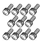
Screw (A)…11 pcs.
Screw (B)…1 pc.
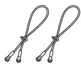
Wire…2 pcs.
Hexagon wrench…1 pc.
Assembly/
Installation Manual


Assembly and installation procedure
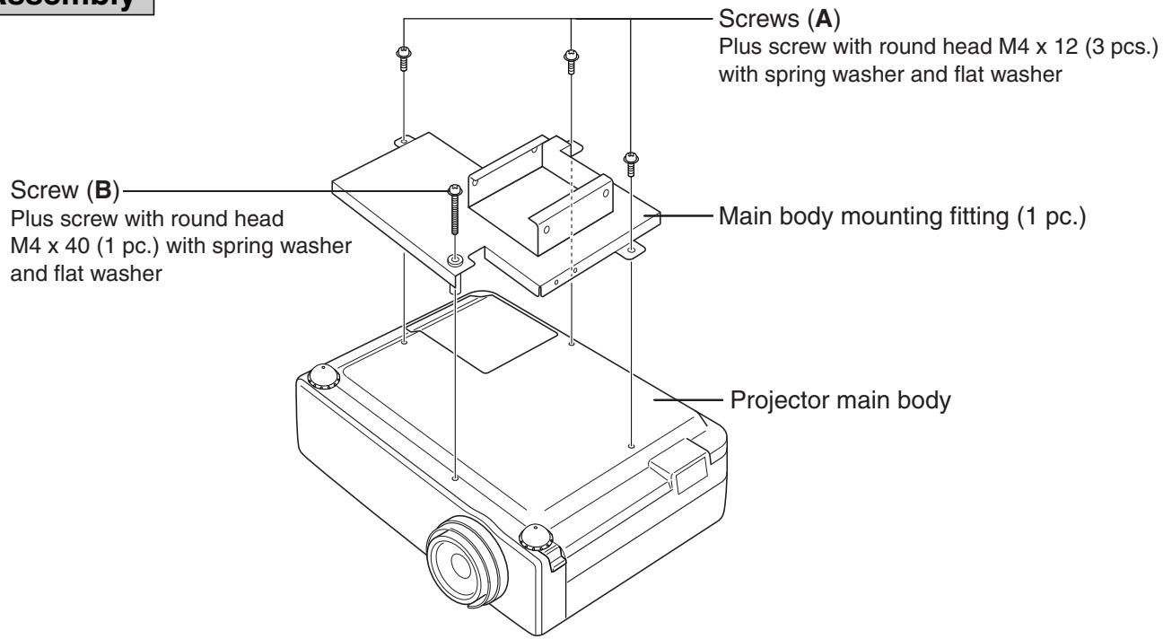
Refer to Fig. 1.
- Turn over the projector main body, and attach it to the main body mounting fitting with screws (A) and (B). (screw (A) ... 3 pcs.) (screw (B) ... 1 pc.)
- Attach the drop prevention wires.
- Attach the ceiling mounting fitting to the ceiling. Refer to the ceiling hanging fitting attachment dimensional drawing.
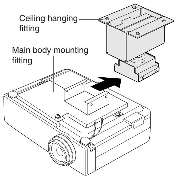
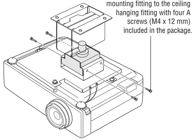
- Slide the main body mounting fitting to which the projector is attached into the ceiling hanging fitting that is attached to the ceiling. Then fix the main body mounting fitting securely to the ceiling hanging fitting with four (A) screws included in the package.
Caution : During this procedure, take care not to drop the projector. Since the projector is hung only temporarily, it is not yet secured.
When wiring, make sure not to let cables or other items block the air inlet or the exhaust port.
This may raise the inside temperature and result in a malfunction.
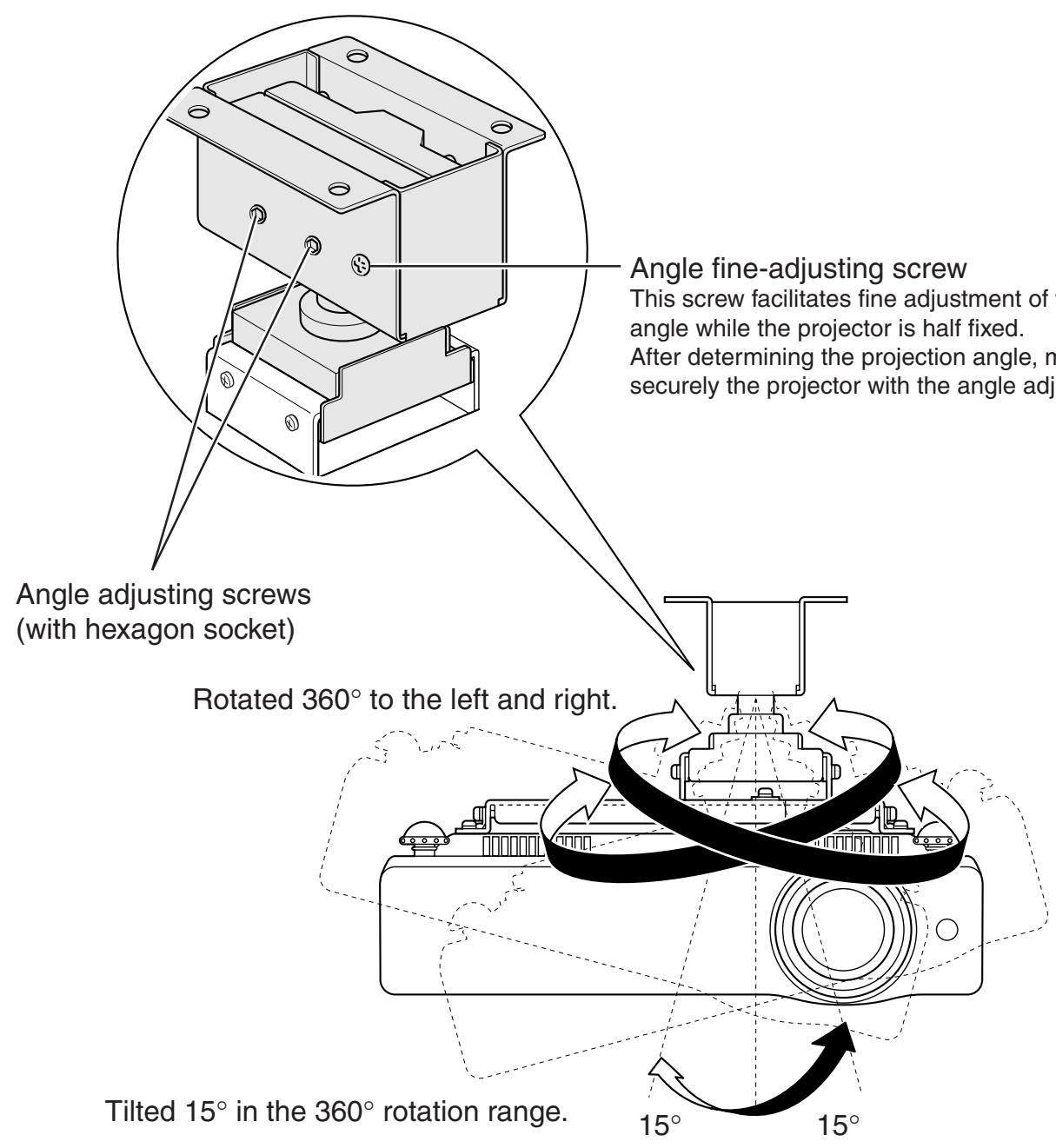
Adjusting the projection position
Refer to Fig. 2.
Adjust the projection position so that an image is projected in the center of the screen. Then tighten the angle adjusting screws securely using the hexagon wrench included in the package.
(If fine adjustment of the angle cannot be smoothly attained, loosen the angle adjusting screws with the hexagon wrench. Then use the angle fine-adjustment screw. This will allow smooth fine adjustment.)
Fig. 1 Assembly
1
text_image
Screw (A) Plus screw with round head M4 x 12 (3 pcs.) with spring washer and flat washer Screw (B) Plus screw with round head M4 x 40 (1 pc.) with spring washer and flat washer Main body mounting fitting (1 pc.) Projector main body2
text_image
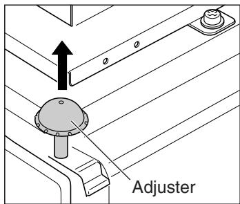
Adjuster- Pull out the adjuster from the projector main body.
text_image
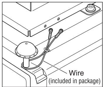
Wire (included in package)- Hang securely the drop prevention wire included in the package to the adjuster in the main body (2 positions).
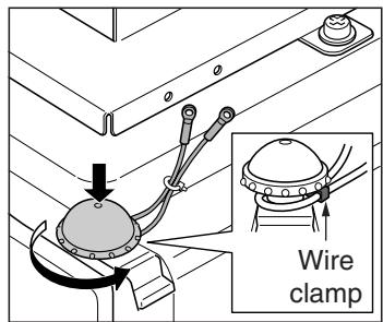
text_image
Wire clamp- Tighten securely the wire clamp with the drop prevention wire, and push down the adjuster in the main body.
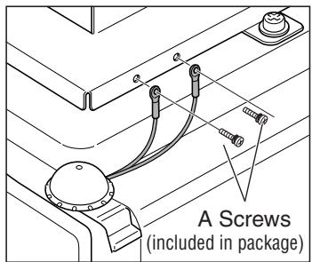
text_image
A Screws (included in package)- Attach the drop prevention wire to the main body mounting fitting with two A screws (M4 x 12 mm) included in the package. Attach the drop prevention wire on the opposite side in the same way.

Measures to prevent the projector from falling
* Make sure to take measures to prevent the projector main body from falling as explained here.
3
text_image
Ceiling hanging fitting Main body mounting fitting4
text_image
mounting fitting to the ceiling hanging fitting with four A screws (M4 x 12 mm) included in the package.Fig. 2 Adjustment
text_image
Angle fine-adjusting screw This screw facilitates fine adjustment of the angle while the projector is half fixed. After determining the projection angle, it is securely the projector with the angle adjusting screw. Angle adjusting screws (with hexagon socket) Rotated 360° to the left and right. Tilted 15° in the 360° rotation range. 15° 15°CAUTION

After the projector angle is fixed once, if the angle is adjusted again in the fixed status, the fixed area may be deformed and adjustment might no longer be possible. Loosen the angle adjusting screws before adjusting the angle again.
If the angle is not proper, adjust the angle again.
After adjustment, confirm that the projector is fixed securely.
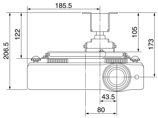
Front view
(Unit: mm)
text_image
185.5 122 206.5 105 173 43.5 80Side view
(Unit: mm)
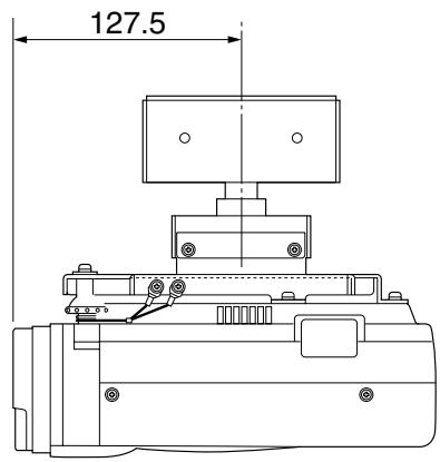
text_image
127.5Ceiling hanging fitting mounting dimensions
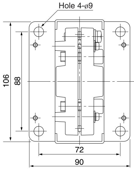
text_image
Hole 4-Ø9 106 88 72 90■ Approximate projection distance
| Screen size (diagonal)(inch) | 40 | 60 | 70 | 80 | 90 | 100 | 110 | 120 | 150 | 200 | 250 | 300 |
| Maximum zoom | 1.0m | 1.5m | 1.8m | 2.0m | 2.3m | 2.5m | 2.8m | 3.1m | 3.8m | 5.1m | 6.4m | 7.7m |
| Minimum zoom | 1.6m | 2.4m | 2.8m | 3.2m | 3.6m | 4.0m | 4.4m | 4.8m | 6.0m | — | — | — |
* Each approximate projection distance is a calculated value based on lens design specifications.
An error of approximately 5% maximum may occur due to lens quality, etc.