
S200 - Power amplifier NAD - Free user manual and instructions
Find the device manual for free S200 NAD in PDF.
| Product Type | Stereo Power Amplifier |
| Brand | NAD |
| Model | S200 |
| Power Supply | 100-240V AC, 50/60 Hz (switchable via dealer) |
| Maximum Power Consumption | 800 W |
| Main Features | Soft Clipping, bridging mode (mono), balanced XLR and unbalanced RCA inputs, thermal and short-circuit protection |
| Inputs | 2x unbalanced RCA, 2x balanced XLR (per channel) |
| Speaker Outputs | High-current binding posts with protective sleeves (L+, L-, R+, R-) |
| Recommended Load Impedance | 4 Ω to 8 Ω (8 Ω minimum in bridging mode) |
| Protection | Thermal and short-circuit protection relay; internal fuses |
| LED Indicators | Power (blue), Protection (blue), Soft Clipping, Bridge Mode |
| Ventilation | Grilles on top and bottom; do not obstruct |
| Maintenance and Cleaning | Clean with a soft dry cloth; avoid contact with liquids |
| Safety | Do not open the device; entrust any repairs to a qualified technician; disconnect the power cord before servicing |
| Spare Parts and Repairability | Internal fuses replaceable by a technician; contact NAD after-sales service for other parts |
| General Information | High-power amplifier with toroidal transformer; can be used in stereo or bridged mono |
Frequently Asked Questions - S200 NAD
User questions about S200 NAD
0 question about this device. Answer the ones you know or ask your own.
Ask a new question about this device
Download the instructions for your Power amplifier in PDF format for free! Find your manual S200 - NAD and take your electronic device back in hand. On this page are published all the documents necessary for the use of your device. S200 by NAD.
USER MANUAL S200 NAD
text_image
NAD Stereo Power Amplifier 3200 PRODUCTION MINT SUPPLANS DEGREE MOGGB Owner's Manual
F Manuel d'Installation
D Bedienungsanleitung
E Manual del Usuario
Manuale delle Istruzioni
P Manual do Proprietário
S Bruksanvisning
IMPORTANT SAFETY INSTRUCTIONS
CAUTION
RISK OF ELECTRIC SHOCK DO NOT OPEN
ATTENTION:
RISQUE DE CHOC ELECTRIQUE NE PAS OUVRIR

CAUTION: TO REDUCE THE RISK OF ELECTRIC SHOCK, DO NOT REMOVE COVER (OR BACK). NO USER SERVICEABLE PARTS INSIDE. REFER SERVICING TO QUALIFIED SERVICE PERSONNEL.
Warning: To reduce the risk of fire or electric shock, do not expose this unit to rain or moisture.
The lightning flash with an arrowhead symbol within an equilateral triangle, is intended to alert the user to the presence of uninsulated "dangerous voltage" within the product's enclosure that may be of sufficient magnitude to constitute a risk of electric shock to persons.
The exclamation point within an equilateral triangle is intended to alert the user to the presence of important operating and maintenance (servicing) instructions in the literature accompanying the product.
Do not place this unit on an unstable cart, stand or tripod, bracket or table. The unit may fall, causing serious injury to a child or adult and serious damage to the unit. Use only with a cart, stand, tripod, bracket or table recommended by the manufacturer or sold with the unit. Any mounting of the device on a wall or ceiling should follow the manufacturer's instructions and should use a mounting accessory recommended by the manufacturer.
An appliance and cart combination should be moved with care. Quick stops, excessive force and uneven surfaces may cause the appliance and cart combination to overturn.
Read and follow all the safety and operating instructions before connecting or using this unit. Retain this notice and the owner's manual for future reference.
All warnings on the unit and in its operating instructions should be adhered to.
Do not use this unit near water; for example, near a bath tub, washbowl, kitchen sink, laundry tub, in a wet basement or near a swimming pool.
The unit should be installed so that its location or position does not interfere with its proper ventilation. For example, it should not be situated on a bed, sofa, rug or similar surface that may block the ventilation openings; or placed in a built-in installation, such as a bookcase or cabinet, that may impede the flow of air through its ventilation openings.
The unit should be situated from heat sources such as radiators, heat registers, stoves or other devices (including amplifiers) that produce heat.
The unit should be connected to a power supply outlet only of the voltage and frequency marked on its rear panel.
The power supply cord should be routed so that it is not likely to be walked on or pinched, especially near the plug, convenience receptacles, or where the cord exits from the unit.
Unplug the unit from the wall outlet before cleaning. Never use benzine, thinner or other solvents for cleaning. Use only a soft damp cloth.
The power supply cord of the unit should be unplugged from the wall outlet when it is to be unused for a long period of time.
Care should be taken so that objects do not fall, and liquids are not spilled into the enclosure through any openings.
This unit should be serviced by qualified service personnel when:
A. The power cord or the plug has been damaged; or
B. Objects have fallen, or liquid has been spilled into the unit; or
C. The unit has been exposed to rain or liquids of any kind; or
D. The unit does not appear to operate normally or exhibits a marked change in performance; or
E. The device has been dropped or the enclosure damaged.
DO NOT ATTEMPT SERVICING OF THIS UNIT YOURSELF. REFER SERVICING TO QUALIFIED SERVICE PERSONNEL
Upon completion of any servicing or repairs, request the service shop's assurance that only Factory Authorized Replacement Parts with the same characteristics as the original parts have been used, and that the routine safety checks have been performed to guarantee that the equipment is in safe operating condition. REPLACEMENT WITH UNAUTHORIZED PARTS MAY RESULT IN FIRE, ELECTRIC SHOCK OR OTHER HAZARDS.
ATTENTION
POUR ÉVITER LES CHOC ELECTRIQUES, INTRODUIRE LA LAME LA PLUS LARGE DE LA FICHE DANS LA BORNE CORRESPONDANTE DE LA PRISE ET POUSSER JUSQU'AU FOND.
CAUTION
TO PREVENT ELECTRIC SHOCK, MATCH WIDE BLADE OF PLUG TO WIDE SLOT FULLY INSERT.
If an indoor antenna is used (either built into the set or installed separately), never allow any part of the antenna to touch the metal parts of other electrical appliances such as a lamp, TV set etc.
CAUTION POWER LINES
Any outdoor antenna must be located away from all power lines.
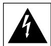
OUTDOOR ANTENNA GROUNDING
If an outside antenna is connected to your tuner or tuner-preamplifier, be sure the antenna system is grounded so as to provide some protection against voltage surges and built-up static charges. Article 810 of the National Electrical Code, ANSI/NFPA No. 70-1984, provides information with respect to proper grounding of the mast and supporting structure, grounding of the lead-in wire to an antenna discharge unit, size of grounding conductors, location of antenna discharge unit, connection to grounding electrodes and requirements for the grounding electrode.
a. Use No. 10 AWG (5.3mm2) copper, No. 8 AWG (8.4mm2) aluminium, No. 17 AWG (1.0mm2) copper-clad steel or bronze wire, or larger, as a ground wire.
b. Secure antenna lead-in and ground wires to house with stand-off insulators spaced from 4-6 feet (1.22 - 1.83 m) apart.
c. Mount antenna discharge unit as close as possible to where lead-in enters house.
d. Use jumper wire not smaller than No.6 AWG (13.3mm2) copper, or the equivalent, when a separate antenna-grounding electrode is used. see NEC Section 810-21 (j).
EXAMPLE OF ANTENNA GROUNDING AS PER NATIONAL ELECTRICAL CODE INSTRUCTIONS CONTAINED IN ARTICLE 810 - RADIO AND TELEVISION EQUIPMENT.
text_image
POWER LINES SERVICE ENTRANCE CONDUCTORS SERVICE ENTRANCE EQUIPMENT GROUND CLAMPS GROUND WIRE a, b BONDING JUMPER d GROUND CLAMP STAND-OFF INSULATORS b MAST ANTENNA LEAD-IN WIRE ANTENNA DISCHARGE UNIT c GROUND WIRE a, b TO EXTERNAL ANTENNA TERMINALS OF PRODUCT GROUND CLAMPS OPTIONAL ANTENNA GROUNDING ELECTRODE. DRIVEN 8 FEET (2.44M) INTO THE EARTH IF REQUIRED BY LOCAL CODES. SEE NEC SECTION 810.21(f).NOTE TO CATV SYSTEM INSTALLER: This reminder is provided to call the CATV system installer's attention to Article 820-40 of the National Electrical Code that provides guidelines for proper grounding and, in particular, specifies that the ground cable ground shall be connected to the grounding system of the building, as close to the point of cable entry as practical.
text_image
Three black-and-white warning symbols: lightning bolt, exclamation mark, and person climbing a ladder with a tool.FRONT PANEL CONTROLS
text_image
NAD Stereo Power Amplifier S200 ©1998 NAD S200 1 2 3 4 5 PROTECTION SOFT CLIPPING BRIDGE MODEREAR PANEL CONNECTIONS
text_image
7 4 3 5 6 SRIGGING (MONO) (STEREO) ON OFF R INPUT UNBALANCED L INPUT BALANCED (BALANCED) BALANCED BALANCE BAL UNBAL SOFT CLIPPING ON OFF SERIAL NUMBER SPEAKERS R + + L - MONO 8-16Ω 2 1 ©1998 NAD S200FIGURE 1
natural_image
Three technical line drawings of mechanical components with curved arrows indicating rotation or assembly (no text or symbols)NAD S200 Stereo Power Amplifier
NOTES ON INSTALLATION
This unit may be installed on any level surface that is strong enough to support its weight. Since its power transformer generates a significant magnetic hum field, a turntable (especially one with a moving-coil pick-up cartridge) or a TV should not be located adjacent to the amplifier or directly above it.
The heat-sink fins make it awkward to lift the S200 by grasping the left and right sides. You may find it more practical to place your hands under the front and rear panels. Much of the amplifier's weight is near the front panel.
CAUTION: The amplifier's weight must always rest on its bottom feet. Never put the amplifier down on its rear panel, with its front panel facing up. Doing so risks damage to the input/output connectors.
The amplifier generates a moderate amount of heat, requiring internal ventilation. Do not permit the air outlet grille on the top cover to be obstructed by papers or articles of clothing. If you want to locate the amplifier on a carpeted floor, place a board under the amplifier in order to prevent it from sinking into the carpet, blocking the air inlets on its bottom.
CAUTION: To prevent a fire or shock hazard, do not permit liquid or moisture to enter the amplifier. If liquid is accidentally spilled on it, immediately shut off the power and unplug the AC Mains cable from the wall outlet.
Do not open the amplifier or attempt to modify or repair it yourself. Refer all servicing to a qualified technician.
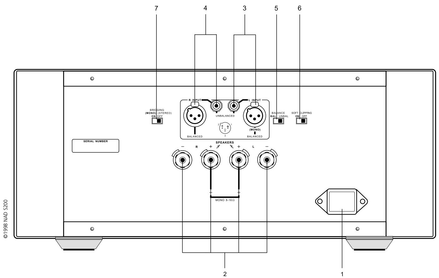
REAR PANEL CONNECTIONS
1. IEC AC MAINS (POWER) INPUT
The NAD S200 comes supplied with a separate AC Mains cable. Before connecting the cable to a live wall socket ensure that it is firmly connected to the S200's AC Mains input socket first. Always disconnect the AC Mains cable plug from the live wall socket first, before disconnecting the cable from the S200 Mains input socket.
Plug the AC Mains cable into a live wall socket. If you must use an extension cord, select a heavy-duty cord of the type used for large electrical appliances.
Do not connect the amplifier's Mains cable to the accessory AC outlets on a preamplifier. Such convenience outlets are not designed to supply the high power levels, up to 800 watts, that the S200 requires. If you wish to switch your entire audio system on and off at once, plug both the S200 and your preamplifier into a “power strip” containing several grounded AC outlets and a high-current on/off switch.
Voltage conversion. A notice printed on the rear indicates the AC power-line voltage that the amplifier requires. However, every model S200 amplifier has a “universal” power supply that can be modified easily for operation in other countries. If you wish to transport your S200 to a nation that employs a different power-line voltage, an authorised NAD dealer or service agency can convert it for such use.
2. SPEAKERS
This amplifier is equipped with special high-current binding post speaker terminals to handle the highest peak power levels that may occur in the “bridged” mode or with low-impedance speakers. At moments when the amplifier is producing maximum power, voltages of nearly 100 V may be present on the speaker terminals, so the terminals are protected by transparent plastic covers.
To connect loudspeaker cables, first switch off the amplifier's power. If you are connecting a pair of speakers for normal stereo operation, be sure that the bridging switch is set to OFF (STEREO).
For best stereo imaging, the left and right speakers should be located at equal distances from your chair. To minimise the effect of speaker cables on the sound, locate the amplifier near the speakers and use short cables to connect the speakers. If your preamplifier is located at the opposite end of the room near your chair, you will need a long cable to connect it to the power amplifier. All NAD preamplifiers have the low output impedance required to drive long connecting cables.
Connect the wires from your left channel speaker to the (L+) and (L-) terminals on the rear panel of the S200, and connect the wires from the right channel speaker to the (R+) and (R-) terminals. In each channel, the red terminal is the positive (+) output, and the black terminal is the negative (-) or "ground" terminal.
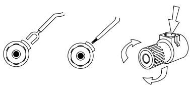
Use heavy duty (16-gauge/2 sq.mm or thicker) wire, especially with 4 ohm loudspeakers. Bare wires can be connected directly to the binding post terminals. For a longer lasting and more corrosion resistant connection, you may purchase speaker cables with gold plated connectors (pin connectors or spade lugs), or you can install such connectors on the wires yourself. Connections to each binding post may be made in several ways as follows. (See Figure 1.)
- Pin connectors. A pin connector is a slim metal shaft that is crimped or soldered onto the end of a wire. The threaded shaft of each binding post contains an opening that accepts pin connectors up to 3mm in diameter. Unscrew the plastic bushing on each terminal to expose the hole in the metal shaft. Insert the pin connector through the hole, and turn the bushing clockwise until it is tight.
- Spade lugs. Unscrew the plastic bushing, insert the U-shaped spade lug into the oblong gap and tighten the bushing down on it.
- Bare wires. Separate the two conductors of the cord (if they appear as a pair), and strip off a half-inch (1cm) of insulation from each. In each conductor, twist together the exposed wire strands. Unscrew the plastic bushings for + and -, insert the bare wire through the hole in the metal shaft, and tighten the plastic bushing until it grasps the wire securely. Check to be sure that no loose strand of wire is touching the chassis or an adjacent terminal. Re-tighten the bushing after a week or so to make sure that any play that may have developed is eliminated.
CAUTION: Safety organisations recommend that the speaker terminals of a very powerful amplifier should be covered. Potentially dangerous voltages are present on these terminals when the amplifier is producing maximum power. For your protection and in order to comply with these regulations, we have chosen speaker terminals of the very highest quality for the NAD S200. These terminals are covered by plastic bushings which prevent the touching of metal parts.
PHASING
Stereo speakers must operate “in phase” with each other to produce a focused stereo image and to reinforce rather than cancel each other’s output at low frequencies. An in-phase connection is assured if the red (positive) terminal on the amplifier is connected to the red (positive) terminal on the loudspeaker in each channel.
If your speakers are easily moved, their phasing can easily be checked. Make the connections to both speakers, place the speakers face-to-face only a few inches apart, play some music, and listen. Then swap the connection of the two wires at the back of ONE of the speakers, and listen again. The connection which produces the fullest, boomiest bass output is the correct one. Connect the wires securely to the speaker terminals, being careful not to leave any loose strands of wire that might touch the wrong terminal and create a partial short-circuit then move the speakers to their intended locations.
If the speakers cannot easily be set face-to-face, then phasing must rely on the "polarity" of the connecting wires. The speaker terminals on the amplifier are identified as red (+) and black (-) in each channel. The terminals at the rear of the speakers are also marked for polarity, either via red and black connectors or by labels: "+" , "1", or "8 ohms" for positive, "-" , "0", or "G" for negative. The red (+) terminal on the amplifier should be connected to the red (positive) terminal of the speaker in each channel.
To facilitate this, the two conductors comprising the speaker wire in each channel are different, either in the colour of the wire itself (copper vs. silver) or in the presence of a small ridge or rib pattern on the insulation of one conductor. Use this pattern to establish consistent wiring to both speakers of a stereo pair. Thus if you connect the copper coloured wire (or ribbed insulation) to the (+) amplifier terminal in the Left channel, do the same in the Right channel. At the other end of the wire, if you connect the copper coloured wire (or the ribbed insulation) to the red or positive terminal on the left channel speaker, do the same at the right channel speaker.
3. LEFT CHANNEL INPUTS (BALANCED/UNBALANCED)
Before making or changing input connections to the amplifier, make certain that the Power is Off.
The S200 amplifier is equipped with two input connectors for each channel. The RCA phono jack is a conventional “unbalanced” input. The three-hole XLR socket is a professional “balanced” input. You may use either type of input, but not both.
If your preamplifier has only conventional outputs with RCA phono jacks, connect an audio connecting cable from the left channel output of the preamplifier to the left channel UNBALANCED input of the S200. Set the BALANCE switch to UNBAL.
If your preamplifier has balanced XLR outputs, connect a three-conductor cable from your left channel preamplifier output to the left-channel XLR input on the S200, and set the BALANCE switch to BAL. If your audio dealer does not have the appropriate cables, purchase balanced “microphone” cables from a shop that sells professional recording equipment. The end of the cable that has a “male” XLR plug (with three metal pins) should be connected to the S200 amplifier. The end of the cable that has a “female” XLR socket (with three holes) should be connected to your preamplifier.
An XLR plug is "keyed" so that it fits into the socket only one way. If there is a set-screw in the barrel of the plug, align it with the top of the connector. Push the plug fully into the XLR socket until it latches in place.
The three pins of an XLR type ("Cannon") connector are numbered. Pin 2 is the signal "hot" connection in the S200, Pin 2 is connected directly to the center pin of the unbalanced RCA phono jack. Pin 3 is the signal return (signal ground) connection. Pin 1 is the chassis earth (ground), to which the shield of a balanced-wire cable is connected.
UNPLUGGING
The XLR socket has a latching feature that prevents the connector from being pulled out by accident. Before disconnecting an input cable, turn off the Power. Use one hand to press the latching tab above the XLR socket while using the other hand to pull the XLR plug out.
4. RIGHT CHANNEL INPUTS (BALANCED/UNBALANCED)
Make connections to the right channel input in the same way that you did for the left channel.
5. INPUT SELECT (BALANCED/UNBALANCED)
Set this switch to match your selection of input connector. Set to UNBAL if you have connected a cable from your preamplifier to the RCA phono input jacks. Set the switch to BAL if you are making connections to the balanced XLR inputs.
Normally the choice of input connector is determined by the output connectors on your preamplifier. If your preamplifier has balanced outputs, use three-conductor cables equipped with XLR connectors. If your preamplifier has only “unbalanced” connections with RCA phono jacks, use the corresponding inputs on the S200.
THE BENEFITS OF BALANCED CONNECTIONS
With a conventional (unbalanced) connection, audio signal current flows from the preamplifier to the power amplifier via the cable's centre conductor. To complete the circuit, audio signal current flows back to the preamplifier ground via the cable's outer conductor. The outer conductor also serves as the cable's shield.
When two audio components are connected together, power-supply noise and “leakage” hum may also flow on the cable shields, combining with the return audio current. The resulting distortion and noise may depend on the orientation of AC power plugs in their sockets. Designers of some audiophile cables combat this contamination by leaving the shield unconnected at one end. Since the shield is grounded at only one end, the performance of such a cable may depend on the direction of its connection, i.e. whether the shield is grounded at the preamplifier or at the power amplifier.
A three-wire balanced connection avoids all of these uncertainties. The signal “hot” and return currents are both carried on inner conductors. The separate cable shield, connected to the amplifier chassis at both ends, protects the audio signal from all forms of interference and power-supply noise. The advantage of this approach is particularly evident with long connecting cables. Therefore, while the S200 can provide excellent sound when used with any preamplifier, the best (and most consistent) performance will be obtained with a preamplifier that has balanced output wiring.
6. SOFT CLIPPING ON/OFF
When an amplifier is overdriven beyond its maximum power output it normally produces “hard clipping” of the signal with harsh distortion and power-supply buzz as the output transistors saturate.
The NAD Soft Clipping circuit gently limits the output waveform and minimises audible distortion when the amplifier is overdriven. It should be switched ON when playing music at very high levels that might exceed the amplifier's power capacity. For convenience it may be left ON at all times.
7. BRIDGING ON (MONO) / OFF (STEREO)
This switch “bridges” the two channels together, forming a monophonic amplifier with more than double the output power. To convert to bridged operation, the following procedure should be followed.
- Switch Off the POWER.
NOTE: In the bridged mode the loudspeaker's impedance is effectively halved as "seen" by the amplifier. An 8 ohm load looks like 4 ohms, a 4 ohm load looks like 2 ohms, and a pair of 4 ohm speakers operated in parallel will resemble a 1 ohm load. Driving paralleled low-impedance speakers to high levels will cause the amplifier to overheat and shut down, or may cause internal fuses to blow in order to protect the amplifier. In bridged mode you must connect only ONE loudspeaker per channel whose nominal impedance is 8 ohms or higher.
- Disconnect any signal cables from the input jacks. Decide whether this amplifier will be driving the left or right speaker. Connect the corresponding (left or right) signal cable from your preamplifier to one of the L input jacks of this amplifier.
NOTE: In the bridged mode the amplifier is driven only through its L (Left) input, even though it may be connected to the right speaker. If another NAD S200 amplifier in bridged mode is used for the second stereophonic channel, it also will be driven through its L input, regardless of whether it is used to drive the left or right loudspeaker.
- Disconnect any wires from the speakers terminals. Select the wire from the speaker that will be driven by this bridged amplifier. Connect its "positive" conductor to the L+ terminal and its "negative" conductor to the R+ terminal (i.e. the two red terminals). Do NOT connect any wires to the black terminals (L- and R-).
CAUTION: In the bridged mode the speaker wires must be "floating" with respect to the circuit ground. Do NOT connect the speaker wires to anything that shares a common ground between stereo channels (such as a speaker switch or an adapter for electrostatic headphones), nor to anything which shares a common ground with the amplifier's inputs (such as a switching comparator or a distortion analyzer).
-
After the preceding conditions have been satisfied, move the BRIDGING switch to ON (MONO). Finally turn the Power ON.
-
To return the amplifier to normal stereo operation at a later date, first turn off the power. Re-set the BRIDGING switch to OFF (STEREO). Restore normal left and right input connections, and reconnect loudspeaker wires to the speaker terminals as described above under SPEAKERS.
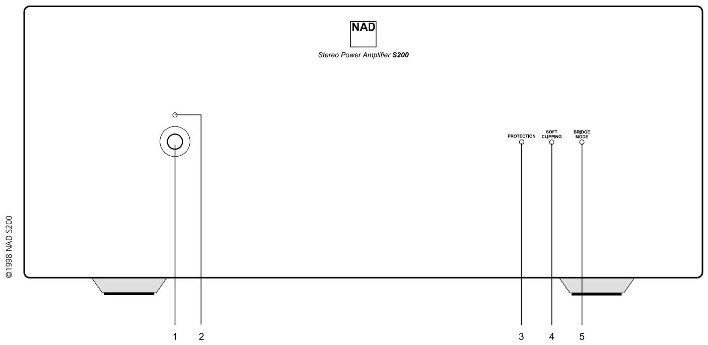
FRONT PANEL CONTROLS
1. POWER ON/OFF
Press the Power button to turn on the amplifier. The blue LED glows when the power is on and the amplifier is ready for use. Press the Power button again to switch the amplifier off.
2. POWER INDICATOR (STATUS)
This blue LED lights up when the S200 is switched on, and indicates the operating status of the amplifier as follows.
DARK: Power off. The Power switch may be off, the AC Mains cable may be unplugged or not connected to a live wall outlet, or the internal fuse may have blown.
BLUE: Power on. The amplifier is ready for use.
3. PROTECTION INDICATOR
This blue LED lights up when the Protection mode is engaged, meaning that the loudspeakers have been disconnected by an internal relay. This mode is activated briefly during turn-on and turn-off, to protect the speakers from low frequency thumps. At other times the Protection mode may be activated by severe overheating, short-circuited speaker wiring, or an internal fault.
If the blue LED indicator lights up continuously, switch the Power Off. When the output stage cools, relays will automatically re-connect the speakers, and normal operation can be resumed. In most cases a very slight reduction in volume level will prevent further interruptions.
If the protection relays interrupt the sound frequently, several possible causes should be considered: A loose strand of wire causing a partial short-circuit between speaker terminals, or continuous high-power operation into a very low impedance in the Bridged mode, or any obstruction of the free flow of air that is needed to ventilate the amplifier and dissipate its heat.
If the protection system interrupts the sound even when the amplifier is cool, return the amplifier to your NAD dealer for service. The protection relays may be disengaging to protect your speakers from a circuit fault, such as an improper DC voltage at the speaker terminals.
4. SOFT CLIPPING INDICATOR
This LED glows when the Soft Clipping switch (on the rear panel) is ON.
5. BRIDGE MODE INDICATOR
This LED glows when the Bridging switch (on the rear panel) is set to ON (STEREO).
| TROUBLESHOOTING | ||
| Problem | Cause | Solution |
| NO SOUND | Power not onThe Protection mode is engaged | Check if AC Mains cable is plugged in and power switched onTurn amplifier off, make sure ventilation slots on top and bottom of amplifier are not blocked. After amplifier has cooled down, turn the amplifier on |
| NO SOUND IN ONE CHANNEL | Speaker cable pulled looseInput cable pulled loose or making poor contact in socketShort-circuit or broken wire in a defective input cable | Check all connections both at the speakers and at the amplifierSwitch the amplifier off, rotate RCA phono input sockets to restore good contact. Check the connection at the preamplifier end of the signal cableSwitch the S200 off, check and replace cables if necessary |
| WEAK BASS/POOR STEREO IMAGING | Loudspeakers wired out of phaseBridging switch set to ON (MONO) while speakers are connected for stereo operation | Swap connections at the back of ONE speakerRe-set the Bridging switch to Off (STEREO) |

6. ECRETAGE DOUX ARRET/MARCHE [SOFT CLIPPING ON/OFF]
7. PONTAGE MARCHE (MONO)/ARRET (STEREO) [BRIDGING ON (MONO)/OFF (STEREO)]
1. MARCHE/ARRET [POWER ON/OFF]
1. IEC AC MAINS (POWER) INPUT - INPUT (ALIMENTAZIONE) RETE C.A. IEC
1. "POWER ON/OFF" (ACCESO/SPENTO)
FÖRDELARNA MED BALANSERAD SIGNALÖVERFÖRING
©1998 NAD ELECTRONICS LTD
LONDON ENGLAND