
M25 - Power amplifier NAD - Free user manual and instructions
Find the device manual for free M25 NAD in PDF.
| Product Type | Seven-channel Power Amplifier |
| Brand | NAD |
| Model | M25 |
| Output Power (Continuous) | 160 W per channel (22.0 dBW) into 8 Ω or 4 Ω, 20 Hz-20 kHz, all 7 channels driven with distortion ≤ 0.03% |
| IHF Dynamic Power | ≥ 220 W into 8 Ω, ≥ 385 W into 4 Ω, ≥ 485 W into 2 Ω |
| Total Harmonic Distortion | 0.03% (20 Hz - 20 kHz) |
| Frequency Response | 20 Hz - 20 kHz ± 0.2 dB; -3 dB at 3 Hz and 70 kHz |
| Signal-to-Noise Ratio (A-weighted) | 96 dB ref. 1 W; 118 dB ref. 160 W |
| Voltage Gain | 29 dB |
| Input Impedance | 1 MΩ / 180 pF |
| Damping Factor | 180 (ref. 8 Ω, 50 Hz) |
| Inputs | 7 x RCA (line); 1 x 12V Trigger (3.5 mm jack) |
| Speaker Outputs | 7 pairs of binding posts (accept spade, banana, bare wire) |
| Power Supply | 115 V / 230 V AC (selectable); Holngren™ toroidal transformer |
| Power Consumption | Internal fuse (type and rating identical to original fuse) |
| Special Features | Soft Clipping; PowerDrive; THX® Ultra2™ certification; individual channel protection (overheat, DC, short circuit); 12 V trigger (remote standby/on) |
| Net Dimensions (W x H x D) | 435 x 200 x 466 mm (without feet) |
| Overall Dimensions | 435 x 215 x 495 mm (feet and connectors included) |
| Net Weight | 43.7 kg |
| Shipping Weight | 52 kg |
| Maintenance and Cleaning | Disconnect before cleaning; use a soft, dry cloth; do not block ventilation grilles; provide at least 75 mm clearance above and 25 mm on sides |
| Included Accessories | IEC power cord; user manual |
| Warranty | Refer to manual or your dealer |
Frequently Asked Questions - M25 NAD
User questions about M25 NAD
0 question about this device. Answer the ones you know or ask your own.
Ask a new question about this device
Download the instructions for your Power amplifier in PDF format for free! Find your manual M25 - NAD and take your electronic device back in hand. On this page are published all the documents necessary for the use of your device. M25 by NAD.
USER MANUAL M25 NAD
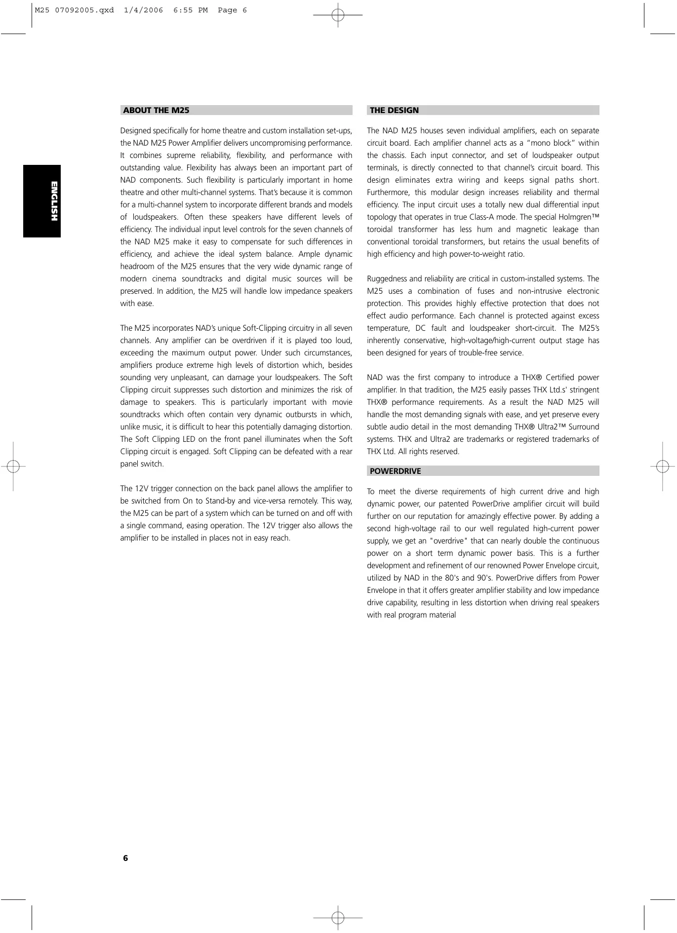
Seven Channel Power Amplifier
text_image
M25 seven channel power amplifier NAD scpt clapping cn 1 cn 2 cn 3 cn 4 cn 5 cn 6 cn 7 THX OUTR20Owner's Manual
IMPORTANT SAFETY INSTRUCTIONS
IMPORTANT SAFETY INSTRUCTIONS
- Save these instructions for later use.
- Follow all warnings and instructions marked on the audio equipment.
1 Read instructions - All the safety and operating instructions should be read before the product is operated.
2 Retain instructions - The safety and operating instructions should be retained for future reference.
3 Heed Warnings - All warnings on the product and in the operating instructions should be adhered to. 4 Follow Instructions - All operating and use instructions should be followed.
5 Cleaning - Unplug this product from the wall outlet before cleaning. Do not use liquid cleaners or aerosol cleaners. Use a damp cloth for cleaning.
6 Attachments - Do not use attachments not recommended by the product manufacturer as they may cause hazards.
7 Water and Moisture - Do not use this product near water-for example, near a bath tub, wash bowl, kitchen sink, or laundry tub; in a wet basement; or near a swimming pool; and the like.
8 Accessories - Do not place this product on an unstable cart, stand, tripod, bracket, or table. The product may fall, causing serious injury to a child or adult, and serious damage to the product. Use only with a cart, stand, tripod, bracket, or table recommended by the manufacturer, or sold with the product. Any mounting of the product should follow the manufacturer's instructions, and should use a mounting accessory recommended by the manufacturer.
9 A product and cart combination should be moved with care. Quick stops, excessive force, and uneven surfaces may cause the product and cart combination to overturn.
10 Ventilation - Slots and openings in the cabinet are provided for ventilation and to ensure reliable operation of the product and to protect it from overheating, and these openings must not be blocked or covered. The openings should never be blocked by placing the product on a bed, sofa, rug, or other similar surface. This product should not be placed in a built-in installation such as a bookcase or rack unless proper ventilation is provided or the manufacturer's instructions have been adhered to.
11 Power Sources - This product should be operated only from the type of power source indicated on the marking label. If you are not sure of the type of power supply to your home, consult your product dealer or local power company.
- Main Power Disconnect; When the power switch is in the Off position, the amplifier is not completely disconnected from the main power. The primary method of isolating the amplifier from the mains supply is to disconnect the mains plug. Ensure that the mains plug remains accessible at all times. When installing the product, ensure that the plug is easily accessible.
- Non-use Period; Unplug the AC power cord from the AC outlet if the unit will not be used for a long period of time such as several months or more.
- CLASS 1 Products; The M25 shall be connected to a MAINS socket outlet with a protective earthing connection.
12 Power-Cord Protection - Power-supply cords should be routed so that they are not likely to be walked on or pinched by items placed upon or against them, paying particular attention to cords at plugs, convenience receptacles, and the point where they exit from the product.
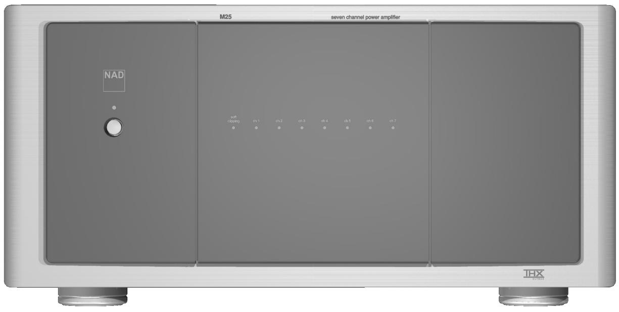
13 Outdoor Antenna Grounding - If an outside antenna or cable system is connected to the product, be sure the antenna or cable system is grounded so as to provide some protection against voltage surges and built-up static charges. Article 810 of the National Electrical Code, ANSI/NFPA 70, provides information with regard to proper grounding of the mast and supporting structure, grounding of the lead-in wire to an antenna discharge unit, size of grounding conductors, location of antenna discharge unit, connection to grounding electrodes, and requirements for the grounding electrode.
NOTE TO CATV SYSTEM INSTALLER
- This reminder is provided to call the CATV system installer's attention to Section 820-40 of the NEC which provides guidelines for proper grounding and, in particular, specifies that the cable ground shall be connected to the grounding system of the building, as close to the point of cable entry as practical.
14 Lightning - For added protection for this product during a lightning storm, or when it is left unattended and unused for long periods of time, unplug it from the wall outlet and disconnect the antenna or cable system. This will prevent damage to the product due to lightning and power-line surges.
15 Power Lines - An outside antenna system should not be located in the vicinity of overhead power lines or other electric light or power circuits, or where it can fall into such power lines or circuits. When installing an outside antenna system, extreme care should be taken to keep from touching such power lines or circuits as contact with them might be fatal.
16 Overloading - Do not overload wall outlets, extension cords, or integral convenience receptacles as this can result in a risk of fire or electric shock.
17 Object and Liquid Entry - Never push objects of any kind into this product through openings as they may touch dangerous voltage points or short-out parts that could result in a fire or electric shock. Never spill liquid of any kind on the product.
WARNING
18 Transportation - Transport the amplifier in both inner and outer shipping containers. Do not transport the amplifier using one shipping container; to do so may result in damage to either the amplifier or personnel.
text_image
POWER LINES SERVICE ENTRANCE CONDUCTORS SERVICE ENTRANCE EQUIPMENT GROUN CLAMP GROUND CLAMP STAND-OFF INSULATORS b MAST ANTENNA LEAD-IN-WIRE ANTENNA DISCHARGE UNIT c POWER SERVICE GROUNDING ELECTRODE SYSTEM (e.g. Interior metal water pipe) GROUND WIRE a b BONDING JUMPER d GROUND WIRE e b OPTIONAL ANTENNA GROUNDING ELECTRODE DRIVEN & FEET (2.44M) INTO THE EARTH IF REQUIRED BY LOCAL CODES. SEE NEC SECTION 810.21(f). TO EXTERNAL ANTENNA TERMINALS OF PRODUCTIMPORTANT SAFETY INSTRUCTIONS
19 Damage Requiring Service - Unplug this product from the wall outlet and refer servicing to qualified service personnel under the following conditions:
a) When the power-supply cord or plug is damaged.
b) If liquid has been spilled, or objects have fallen into the product.
c) If the product has been exposed to rain or water.
d) If the product does not operate normally by following the operating instructions. Adjust only those controls that are covered by the operating instructions as an improper adjustment of other controls may result in damage and will often require extensive work by a qualified technician to restore the product to its normal operation.
e) If the product has been dropped or damaged in any way.
f) when the product exhibits a distinct change in performance—this indicates a need for service.
20 Replacement Parts - When replacement parts are required, be sure the service technician has used replacement parts specified by the manufacturer or have the same characteristics as the original part. Unauthorized substitutions may result in fire, electric shock, or other hazards.
21 Safety Check - Upon completion of any service or repairs to this product, ask the service technician to perform safety checks to determine that the product is in proper operating condition.
22 Wall or Ceiling Mounting - The product should be mounted to a wall or ceiling only as recommended by the manufacturer.
WARNING

TO PREVENT FIRE OR SHOCK HAZARD, DO NOT EXPOSE THIS APPLIANCE TO RAIN OR MOISTURE. THE LIGHTNING FLASH WITH ARROWHEAD SYMBOL, WITHIN AN EQUILATERAL TRIANGLE, IS INTENDED TO ALERT THE USER TO THE PRESENCE OF UNINSULATED "DANGEROUS VOLTAGE" WITHIN THE PRODUCT'S ENCLOSURE THAT MAY BE OF SUFFICIENT MAGNITUDE TO CONSTITUTE A RISK OF ELECTRIC SHOCK TO PERSONS.

THE EXCLAMATION POINT WITHIN AN EQUILATERAL TRIANGLE IS INTENDED TO ALERT THE USER TO THE PRESENCE OF IMPORTANT OPERATING AND MAINTENANCE (SERVICING) INSTRUCTIONS IN THE LITERATURE ACCOMPANYING THE APPLIANCE
CAUTION
Changes or modifications to this equipment not expressly approved by NAD Electronics for compliance could void the user's authority to operate this equipment.
CAUTION REGARDING PLACEMENT
To maintain proper ventilation, be sure to leave a space around the unit (from the largest outer dimensions including projections) equal to, or greater than, shown below.
Left and Right Panels : 10 cm
Rear Panel : 10 cm
Top Panel : 50 cm
IMPORTANT INFORMATION FOR UK CUSTOMERS
DO NOT cut off the mains plug from this equipment. If the plug fitted is not suitable for the power points in your home or the cable is too short to reach a power point, then obtain an appropriate safety approved extension lead or consult your dealer. If, nonetheless, the mains plug is cut off, REMOVE THE FUSE and dispose of the PLUG immediately, to avoid possible shock hazard by inadvertent connection to the mains supply. If this product is not provided with a mains plug, or one has to be fitted, then follow the instructions given below:
IMPORTANT
DO NOT make any connection to the larger terminal which is marked with the letter 'E' or by the safety earth symbol or coloured GREEN or GREEN AND YELLOW.
The wires in the mains lead on this product are coloured in accordance with the following code:
BLUE - NEUTRAL
BROWN - LIVE
As these colours may not correspond with the coloured markings identifying the terminals in your plug, proceed as follows:
The BLUE wire must be connected to the terminal marked with the letter 'N' or coloured BLACK.
The BROWN wire must be connected to the terminal marked with the letter 'L' or coloured RED
When replacing the fuse, only a correctly rated and approved type should be used, and be sure to re-fit the fuse cover.
IF IN DOUBT CONSULT A COMPETENT ELECTRICIAN
This product is manufactured to comply with the radio interference requirements of EEC DIRECTIVE 89/68/EEC and 73/23/EEC
NOTES ON ENVIRONMENTAL PROTECTION
At the end of its useful life, this product must not be disposed of with regular household waste but must be returned to a collection point for the recycling of electrical and electronic equipment. The symbol on the product, user's manual and packaging, point this out. The materials can be reused in accordance with their markings. Through re-use, recycling of raw materials, or other forms of recycling of old products, you are making an important contribution to the protection of our environment.
Your local administrative office can advise you of the responsible waste disposal point.
Model No.: ____ Serial No.: ____

text_image
CAUTION RISK OF ELECTRIC SHOCK DO NOT OPEN CAUTION : TO REDUCE THE RISK OF ELECTRIC SHOCK, DO NOT REMOVE COVER (OR BACK). NO USER-SERVICEABLE PARTS INSIDE REFER SERVICING TO QUALIFIED SERVICE PERSONNEL.

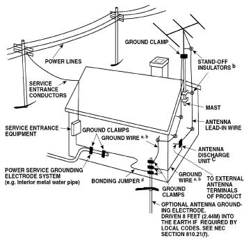
FRONT PANEL CONTROLS
text_image
1 M25 seven channel power amplifier NAD soft clipong ch 1 ch 2 ch 3 ch 4 ch 5 ch 6 ch 7 3 2 IHXPANEL CONNECTIONS/CONTROLS
text_image
NORTH AMERICA VERSION CHANNEL 7 FRONT 3 LEVEL THX INPUT CHANNEL 6 EQUIS 1 LEVEL THX INPUT CHANNEL 5 CHINA 5 CHANNEL 4 CHANNEL 3 CHANNEL 2 CHANNEL 1 CHANNEL 4 CENTER LEVEL THX INPUT CHANNEL 3 EUREA 3 LEVEL THX INPUT CHANNEL 2 SURSEL LEVEL THX INPUT CHANNEL 1 FRONT 1 LEVEL THX INPUT SPEAKER - SPEAKER - SPEAKER - SPEAKER - SPEAKER - CAUTION - ATTENTION MINIMUM SPEAKER IMPEDANCE MINIMUM IMPEDANCE DES HAUTES PARLEURS ONE PAIR 4 OHM MIN. / SPEAKER ONE PAIR 4 OHM MIN. / SPEAKER GROUND ON OFF SOFT CLIPPING OFF ON AUTO TRIGGER +12V TROGER IN 120V~ 60Hz Serial No./No. De Series 230V~ 50Hz CAUTION: REPLACE WITH USE TYPE: UL/20V/USE ATTENTION: UTILISER UN PULSE DE REPAVAGE: MODE TYPE: UL/20V EUROPE VERSION CAUTION: REPLACE WITH USE TYPE: UL/20V/USE ATTENTION: UTILISER UN PULSE DE REPAVAGE: MODE TYPE: UL/20VFIGURE 1
flowchart
graph TD
    A["COMPONENT VIDEO IN"] --> B["VIDEO 4 OUT"]
    A --> C["VIDEO 5 OUT"]
    A --> D["VIDEO 6 OUT"]
    A --> E["VIDEO 7 OUT"]
    A --> F["VIDEO 8 OUT"]
    A --> G["VIDEO 9 OUT"]
    A --> H["VIDEO 10 OUT"]
    A --> I["VIDEO 11 OUT"]
    A --> J["VIDEO 12 OUT"]
    A --> K["VIDEO 13 OUT"]
    A --> L["VIDEO 14 OUT"]
    A --> M["VIDEO 15 OUT"]
    A --> N["VIDEO 16 OUT"]
    A --> O["VIDEO 17 OUT"]
    A --> P["VIDEO 18 OUT"]
    A --> Q["VIDEO 19 OUT"]
    A --> R["VIDEO 20 OUT"]

    S["SPEAKERS"] --> T["DVD IN"]
    S --> U["SAT IN"]
    S --> V["VCR IN"]
    S --> W["OUT"]

    X["AUDIO PRE-OUT TO CHANNEL INPUTS"] --> Y["EXTERNAL 7.1 INPUT FRONT"]
    X --> Z["INTERNATIONAL 7.1 INPUT FRONT"]
    X --> AA["INTERNATIONAL 7.1 INPUT SURR/B CENTER"]
    X --> AB["INTERNATIONAL 7.1 INPUT SURR/B CENTER"]
    X --> AC["INTERNATIONAL 7.1 INPUT SURR/B CENTER"]

    AD["ORI OUT"] --> AE["IR IN"]
    AD --> AF["IR OUT"]

    AG["+12V PROGGER OUT 1"] --> AH["+12V PROGGER OUT 2"]
    AG --> AI["+12V PROGGER OUT 3"]

    AJ["POWER ON"] --> AK["ON"]
    AJ --> AL["OFF"]

    AM["AC OUTLET 120V/Hz"] --> AN["Serial No./No. De Series"]

    AO["R0 320"] --> AP["RS"]

    AQ["120V*/-50Hz"] --> AR["RS"]

    AS["TOMIN IN"] --> AT["1"]
    AS --> AU["2"]
    AS --> AV["3"]
    AS --> AW["4"]
    AS --> AX["5"]
    AS --> AY["6"]
    AS --> AZ["7"]

    BA["OPTICAL"] --> BB["1"]
    BA --> BC["2"]
    BA --> BD["3"]

    BE["GROUND"] --> BF["Ground"]

    BG["TENNYHO CHANNEL 1"] --> BH["MIN. LEVEL THX INPUT"]

    BI["TENNYHO CHANNEL 2"] --> BJ["MIN. LEVEL THX INPUT"]

    BK["TENNYHO CHANNEL 3"] --> BL["MIN. LEVEL THX INPUT"]

    BM["TENNYHO CHANNEL 4"] --> BN["MIN. LEVEL THX INPUT"]

    BO["TENNYHO CHANNEL 5"] --> BP["MIN. LEVEL THX INPUT"]

    BQ["TENNYHO CHANNEL 6"] --> BR["MIN. LEVEL THX INPUT"]

    BS["TENNYHO CHANNEL 7"] --> BT["MIN. LEVEL THX INPUT"]

    BU["TENNYHO CHANNEL 8"] --> BV["MIN. LEVEL THX INPUT"]

    BW["TENNYHO CHANNEL 9"] --> BX["MIN. LEVEL THX INPUT"]

    BY["TENNYHO CHANNEL 10"] --> BZ["MIN. LEVEL THX INPUT"]

    CA["TENNYHO CHANNEL 11"] --> CB["MIN. LEVEL THX INPUT"]

    CC["TENNYHO CHANNEL 12"] --> CD["MIN. LEVEL THX INPUT"]

    CE["TENNYHO CHANNEL 13"] --> CF["MIN. LEVEL THX INPUT"]

    GD["TENNYHO CHANNEL 14"] --> DH["MIN. LEVEL THX INPUT"]

    DI["TENNYHO CHANNEL 15"] --> DJ["MIN. LEVEL THX INPUT"]

    DK["TENNYHO CHANNEL 16"] --> DL["MIN. LEVEL THX INPUT"]

    DV["TENNYHO CHANNEL 17"] --> DW["MIN. LEVEL THX INPUT"]

    BX["TENNYHO CHANNEL 18"] --> BXT["MIN. LEVEL THX INPUT"]

    BY["TENNYHO CHANNEL 19"] --> BYT["MIN. LEVEL THX INPUT"]

    BZ["TENNYHO CHANNEL 20"] --> BZT["MIN. LEVEL THX INPUT"]

    DC["TENNYHO CHANNEL 21"] --> DCB["MIN. LEVEL THX INPUT"]

    DB["TENNYHO CHANNEL 22"] --> DBT["MIN. LEVEL THX INPUT"]

    BE["TENNYHO CHANNEL 23"] --> BEU["MIN. LEVEL THX INPUT"]

    BZ["TENNYHO CHANNEL 24"] --> BZU["MIN. LEVEL THX INPUT"]

    DC["TENNYHO CHANNEL 25"] --> DCV["MIN. LEVEL THX INPUT"]

    BE["TENNYHO CHANNEL 26"] --> BEV["MIN. LEVEL THX INPUT"]

    BZ["TENNYHO CHANNEL 27"] --> BZV["MIN. LEVEL THX INPUT"]

    BZ["TENNYHO CHANNEL 28"] --> BZVT["MIN. LEVEL THX INPUT"]

    BE["TENNYHO CHANNEL 29"] --> BEVY["MIN. LEVEL THX INPUT"]

    BZ["TENNYHO CHANNEL 30"] --> BZVZ["MIN. LEVEL THX INPUT"]

    BE["TENNYHO CHANNEL 31"] --> BEVZT["MIN. LEVEL THX INPUT"]

    BZ["TENNYHO CHANNEL 32"] --> BEVZV["MIN. LEVEL THX INPUT"]

    BZ["TENNYHO CHANNEL 33"] --> BEVZVW["BUX OUT"]

    CC["TENNYHO CHANNEL 34"] --> CCUB["MIN. LEVEL THX INPUT"]

    DB["TENNYHO CHANNEL 35"] --> DBV["MIN. LEVEL THX INPUT"]

    BE["TENNYHO CHANNEL 36"] --> BEVVM["BUX OUT"]

    BZ["TENNYHO CHANNEL 37"] --> BZVVM

    CC["TENNYHO CHANNEL 38"] --> CCVVM

    DE["PUE PULSE"] --> DEP["PULSE OUT"]

    EQ["FROM R"] --> EQF["SURR R"] --> EQG["SURR B R"] --> EQH["CENTER"] --> EQI["SURR B L"] --> EQJ["SURR L"] --> EQK["SURR L"] --> EQL["FROM L"]
FIGURE 2
text_image
Spade Wire PinABOUT THE M25
Designed specifically for home theatre and custom installation set-ups, the NAD M25 Power Amplifier delivers uncompromising performance. It combines supreme reliability, flexibility, and performance with outstanding value. Flexibility has always been an important part of NAD components. Such flexibility is particularly important in home theatre and other multi-channel systems. That's because it is common for a multi-channel system to incorporate different brands and models of loudspeakers. Often these speakers have different levels of efficiency. The individual input level controls for the seven channels of the NAD M25 make it easy to compensate for such differences in efficiency, and achieve the ideal system balance. Ample dynamic headroom of the M25 ensures that the very wide dynamic range of modern cinema soundtracks and digital music sources will be preserved. In addition, the M25 will handle low impedance speakers with ease.
The M25 incorporates NAD's unique Soft-Clipping circuitry in all seven channels. Any amplifier can be overdriven if it is played too loud, exceeding the maximum output power. Under such circumstances, amplifiers produce extreme high levels of distortion which, besides sounding very unpleasant, can damage your loudspeakers. The Soft Clipping circuit suppresses such distortion and minimizes the risk of damage to speakers. This is particularly important with movie soundtracks which often contain very dynamic outbursts in which, unlike music, it is difficult to hear this potentially damaging distortion. The Soft Clipping LED on the front panel illuminates when the Soft Clipping circuit is engaged. Soft Clipping can be defeated with a rear panel switch.
The 12V trigger connection on the back panel allows the amplifier to be switched from On to Stand-by and vice-versa remotely. This way, the M25 can be part of a system which can be turned on and off with a single command, easing operation. The 12V trigger also allows the amplifier to be installed in places not in easy reach.
THE DESIGN
The NAD M25 houses seven individual amplifiers, each on separate circuit board. Each amplifier channel acts as a "mono block" within the chassis. Each input connector, and set of loudspeaker output terminals, is directly connected to that channel's circuit board. This design eliminates extra wiring and keeps signal paths short. Furthermore, this modular design increases reliability and thermal efficiency. The input circuit uses a totally new dual differential input topology that operates in true Class-A mode. The special Holmgren™ toroidal transformer has less hum and magnetic leakage than conventional toroidal transformers, but retains the usual benefits of high efficiency and high power-to-weight ratio.
Ruggedness and reliability are critical in custom-installed systems. The M25 uses a combination of fuses and non-intrusive electronic protection. This provides highly effective protection that does not effect audio performance. Each channel is protected against excess temperature, DC fault and loudspeaker short-circuit. The M25's inherently conservative, high-voltage/high-current output stage has been designed for years of trouble-free service.
NAD was the first company to introduce a THX® Certified power amplifier. In that tradition, the M25 easily passes THX Ltd.s' stringent THX® performance requirements. As a result the NAD M25 will handle the most demanding signals with ease, and yet preserve every subtle audio detail in the most demanding THX® Ultra2™ Surround systems. THX and Ultra2 are trademarks or registered trademarks of THX Ltd. All rights reserved.
POWERDRIVE
To meet the diverse requirements of high current drive and high dynamic power, our patented PowerDrive amplifier circuit will build further on our reputation for amazingly effective power. By adding a second high-voltage rail to our well regulated high-current power supply, we get an "overdrive" that can nearly double the continuous power on a short term dynamic power basis. This is a further development and refinement of our renowned Power Envelope circuit, utilized by NAD in the 80's and 90's. PowerDrive differs from Power Envelope in that it offers greater amplifier stability and low impedance drive capability, resulting in less distortion when driving real speakers with real program material
INSTALLATION PRECAUTIONS
WARNING - To reduce the risk of fire or electrical shock, do not expose the amplifier to rain or moisture.
CAUTION - For units factory-set at 115 volts AC match the wide blade of the power plug to the wide slot of the power outlet, to prevent electrical shock. Be sure the plug is completely inserted into the receptacle.
Turn off all the components in the system whenever connecting or disconnecting any audio signal wiring. Once all signal connections have been completed, turn down all the system's main volume control before turning the system components on. Then increase the volume control setting carefully to avoid damage to the system components.
NOTES ON INSTALLATION LOCATION
Read and follow all the safety instructions on the first page of this manual. To prevent a fire or shock hazard, do not place the amplifier where it will be exposed to any water or moisture. If liquid accidentally gets into the amplifier, immediately unplug the AC power cord. Do not operate the amplifier again until it has been examined by a service technician.
The amplifier generates a moderate amount of heat, requiring ventilation. Do not obstruct the air outlet grilles on the top or bottom covers. There should be at least 3 inches (7.5 cm) of clearance above the amplifier and 1 inch (2.5 cm) to the sides. Do not place the amplifier in an enclosed area, such as in a bookcase or in a cabinet, unless it is very well ventilated. Be sure there is adequate room behind the amplifier for signal input and speaker output connections. If you want to locate the amplifier on a carpeted floor, place a board under it in order to prevent it from sinking into the carpet, blocking the air inlets on the bottom. Do not place the amplifier where it will be exposed to direct sun light for prolonged periods of time.
This unit may be installed on any sturdy, level surface.
]NOTES: The amplifier's weight must always rest on its bottom feet. Never put the amp down on its rear panel, with its front panel facing up. Doing so risks damage to the input/output connectors.
The power transformer in the M25 generates a magnetic hum field of moderate strength. Turntables (especially those with a moving-coil pickup cartridge) should not be located near the amplifier. Magnetic media, such as audio or video tapes and computer diskettes, should not be stored near the amplifier.
TRANSPORTATION
Transport - Transport the amplifier in both inner and outer shipping containers. Do not transport the apparatus using one shipping container; to do so may result in damage to either the apparatus or personnel.
SAVE ALL THE PACKAGING
Please save both boxes and all of the packaging in which your M25 arrived. Should you move or otherwise need to transport your amplifier, this is by far the safest set of containers in which to do so. We've seen too many otherwise perfect components damaged in transit for lack of proper shipping cartons, so please: Save both inner and outer boxes!
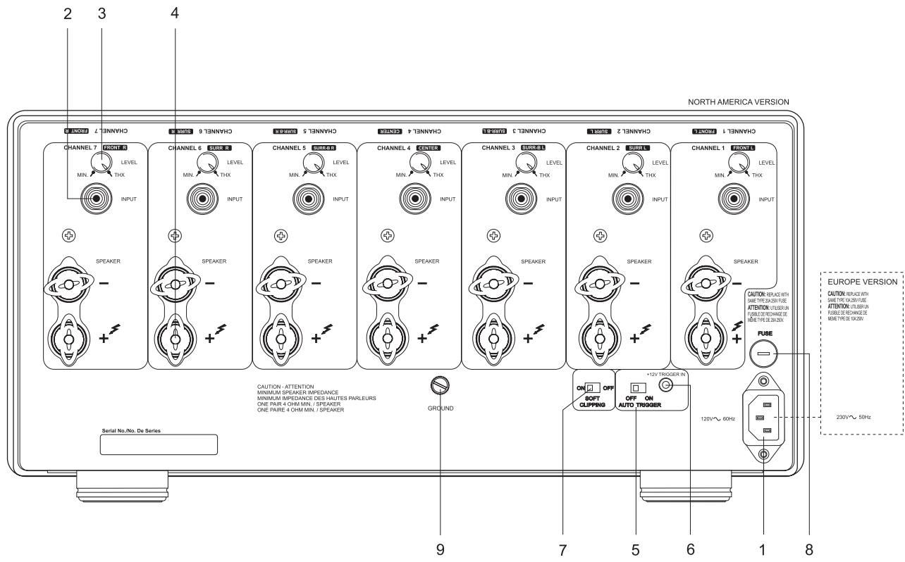
REAR PANEL CONNECTIONS/CONTROLS
1. IEC POWER SOCKET
Connect to the supplied IEC-standard removable AC power cord before connecting the AC power cord to the wall socket.
NOTE: Before connecting the AC-power cord to a live wall socket insure that all inputs/outputs are connected first. Always disconnect the AC power cord plug from the live wall socket first, before disconnecting any cable from the M25 amplifier. If you must use an extension cord, select a heavy-duty cord of the type used for large electrical appliances, such as an air conditioner AC-extension cord (16 AWG). We strongly recommend that you not connect the amplifier's mains cable to the accessory AC outlets on a preamplifier. Such convenience outlets are not designed to supply the high-power levels that the NAD M-series amplifier requires.
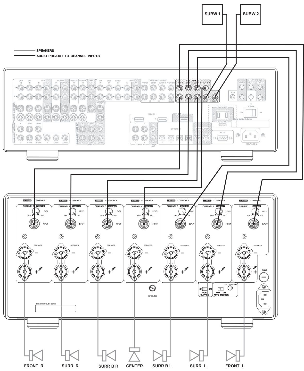
2. INPUTS
Each of the seven independent power amplifiers within the M25 has its own signal input connector. Before making any connections to the amplifier, make sure the POWER is switched OFF. [See figure 1]
Connect the signal cables from the preamplifier, surround sound decoder, or other signal source to these inputs. For optimum heat dissipation in an AV surround system, we recommend you allocate the audio channels to the inputs as follows:
Channel 1 = Front Left speaker
Channel 2 = Surround Left speaker
Channel 3 = Surround Back Left speaker
Channel 4 = Center speaker
Channel 5 = Surround Back Right speaker
Channel 6 = Surround Right speaker
Channel 7 = Front Right speaker
3. INPUT LEVEL CONTROLS
The amplifier is equipped with separate input level controls for each channel. Before turning on the M25 for the first time, make sure all level controls are in their normal full-clockwise position. With the input levels set to the maximum position, the gain is exactly conforming to THX Ultra _2^TM standards.
Under some circumstances, other settings may be useful for:
- Level-matching - In systems that incorporate speakers of varying efficiencies, it may be necessary to reduce the settings of some controls to achieve proper channel-to-channel balance.
- Extended volume-control range - Many stereo systems have so much voltage gain that the speakers (or your ears) are over-driven at any volume-control setting higher than 11 or 12 o'clock position of the volume control. As a result you can use only the lower half of the volume control's range, where adjustments are imprecise and channel-balance errors tend to be greater. If all input level controls are reduced, you can turn up your preamplifier's volume control, making effective use of most of its range. (Suggestion: Adjust the input level controls so that your preferred maximum sound levels occur at about 2 or 3 o'clock on the volume control.) As an added benefit, this procedure suppresses any noise produced by the preamp's high-level circuitry (e.g. any residual hum or hiss that does not go away when the Volume is turned down).
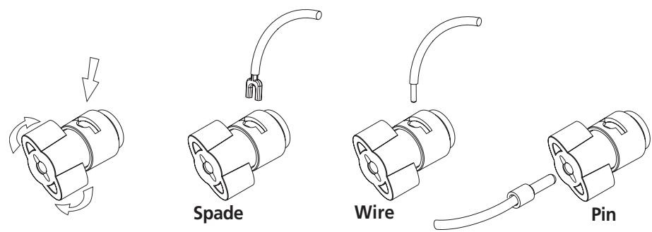
4. SPEAKER CONNECTIONS
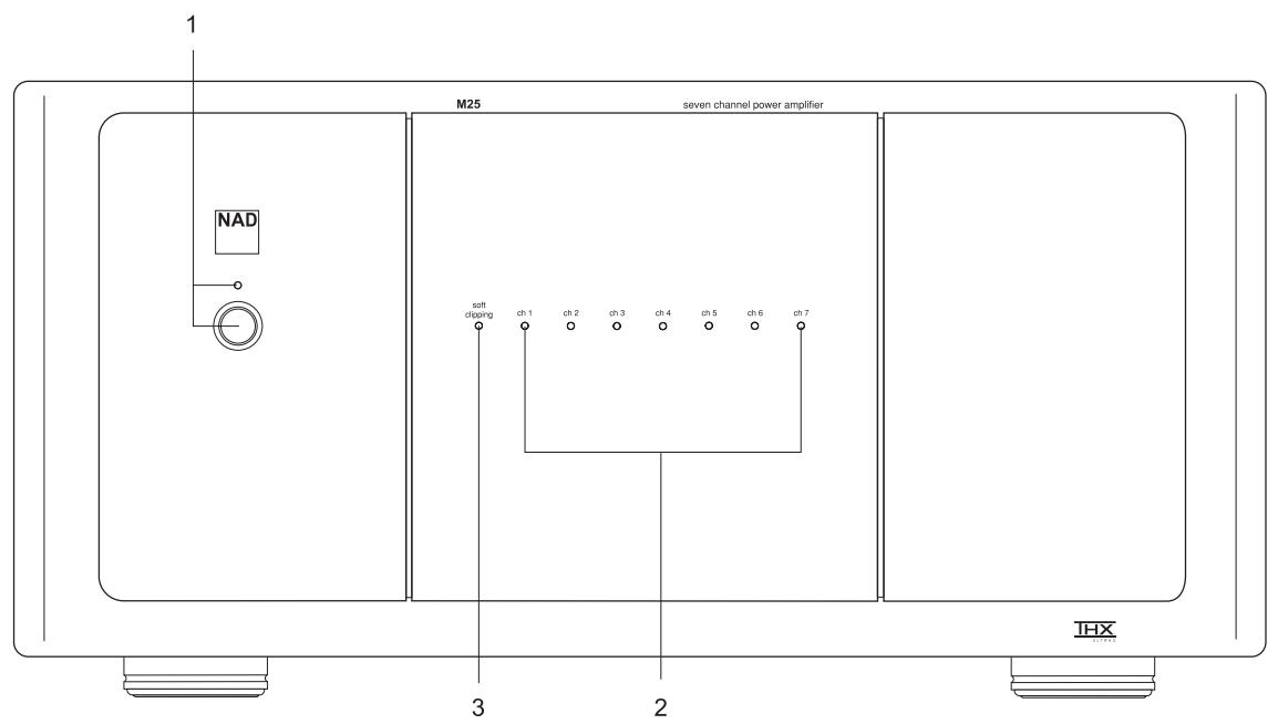
This amplifier is equipped with special high-current binding-post speaker terminals. Connect the loudspeakers with heavy-duty (16-gauge or thicker) braided wire. Connections may be made in any of three ways. [See Figure 2.]
- Strip off a half-inch (1 cm) of insulation from each speaker wire. In each conductor, twist the thin strands of wire together. Unscrew the knob, insert the bare wire into the opening at the base of the binding post, and tighten the knob until it grasps the wire securely. Check to be sure that there are no loose strands of wire touching the chassis or an adjacent terminal.
- Spade lugs. Unscrew the knob, insert the U-shaped spade lug behind the bushing, and tighten the knob until the spade lug is secured.
- Install banana plugs on your speaker wires, and plug them into the end of each binding post.
NOTE: Speakers must operate in phase with each other in order to produce a proper stereo image and to reinforce rather than cancel each other's output at low frequencies. When connecting speakers, take care that the red (positive) terminal on each loudspeaker is connected to the corresponding terminal marked red (positive) on the amplifier.
5. AUTO TRIGGER ON/OFF
Set the Auto Trigger switch to the ON position to activate the 12V-trigger. By connecting the 12V-trigger, the M25 can be remotely switched to On and Standby and vice-versa. When set to the Off position, the 12V-trigger input is not active.
NOTE: With the Auto Trigger switch set to the ON position and the 12V-trigger input connected, the M25 will switch from Off to Stand-by when the Power Switch on the front panel is pressed. For normal operation, ensure the switch is in the OFF position or that the 12V-trigger input socket is not connected.
6. 12V-TRIGGER INPUT
For external Power on/Stand-by switching, connect the 12V-trigger output of a source component to this DC input jack. The center pin is the live or + connection, the outer sleeve of the input jack is the 12V-trigger - or ground connection.
NOTES: The M25's 12V-trigger will work within a range of 6 to 15 V DC level and typically draws less than 10mA of current. Check the specifications of the 12V-trigger source to ensure it is compatible with the M25's 12V-trigger input. Do not exceed the recommended voltage as this may cause damage to the M25.
7. SOFT CLIPPING
When an amplifier is driven beyond its specified power output it normally produces "hard clipping" or distortion of the signal. Such hard clipping, in addition to sounding unpleasant, can damage the speakers in the system. The NAD Soft Clipping circuit gently limits the output waveform, minimizing audible distortion and reducing the change of speaker damage when the amplifier is overdriven. We recommend that the Soft Clipping switch on the back panel of the M25 be left in the ON position when system is being operated at levels that might exceed the amplifier's power capacity. The LED on the front panel indicates if Soft Clipping has been engaged.
8. FUSE HOLDER
There is a fuse holder nearby or next to the AC-line cord. In the unlikely event a fuse may need to be replaced, unplug the line cord from the wall. Then remove all connections from the amplifier. Only replace the fuse with the same type, size, and specification.
9. GROUND CONNECTOR
The M25 is provided with a GROUND terminal on the rear panel. This terminal is connected directly to the chassis of the M25. In the event of radio hum or radio interference, this terminal can be connected to a 'true earth' such as a copper plated rod driven several feet into the ground.
FRONT PANEL CONTROLS
1. POWER SWITCH/STANDBY LED
Press this button to switch the amplifier on or off. The Power LED located just above the power button and Protection LEDs (see Protection LED below) will light up. After a few seconds, the Protection LEDs will switch from red to blue, indicating that the amplifier is ready for use.
The M25 can also be remotely switched from Standby to On and vice-versa using the 12V-trigger input on the back panel. When the M25 is in the Standby mode, the Standby LED will be amber indicating the Standby mode. For the 12V-trigger input to work, the M25 must first be turned on by means of the front panel Power Switch, and the switch must be left in this position. Using the 12V-trigger source component, switch its 12V-trigger output to on and off. The M25's trigger input will now follow the source component's 12V-trigger output. Ensure that the Auto Trigger switch on the back panel is in the ON position and that the 12V-trigger input is connected properly.
2. PROTECTION LED
The Protection LEDs turn red for about 3 seconds, every time the amplifier is switched on. After a few seconds they will turn blue and the amplifier is ready for operation.
These LEDs turn red when one or more of the internal seven amplifiers go into protect mode, but the other amplifiers will continue to function as shown by their blue LEDs so it is likely you will still hear sound.
When the amplifier is switched off from normal operation by means of the front panel power switch, or to Standby via the rear panel trigger source, the Protection LEDs will light up red and will fade out in a couple of seconds..
NOTE: If you see a Protection LED turn red, turn off the amplifier immediately using the front panel Power Switch. Check if all speaker wires are connected correctly and that none of the wires are damaged, causing a short circuit. Another cause may be excessive heat build-up inside the amplifier. Make sure there is adequate ventilation around the amplifier and that none of its ventilation slots, top or bottom, are blocked. After the amplifier has cooled down it will function normally again.
In case one or more of the Protection LEDs remains red despite the checks mentioned above, turn the amplifier off by means of the front panel Power Switch and consult your NAD dealer.
3. SOFT CLIPPING LIGHT
When the Soft Clipping circuit of the M25 is activated the indicator LED on the front panel will light.
TROUBLESHOOTING
| PROBLEM | CAUSE | SOLUTION |
| NO SOUND | Power AC lead unplugged or power not switched on | Check if AC lead is plugged in and power switched on |
| NO SOUND ON ONE CHANNEL | Speaker not properly connected or damaged.Input lead disconnected or damaged | Check connections and speakersCheck leads and connections |
| NO SOUND ON SURROUND CHANNELS | No surround mode selectedMono sound sourceSpeakers not properly connectedSurround volume level too low | Select a Surround ModeTest system with Stereo or Dolby Surround materialCheck speakers and connectionsIncrease surround volume level |
| NO SOUND ON CENTER CHANNEL | Speaker not connected properlyCenter volume level set too low | Check speaker and connectionIncrease center volume level |
| WEAK BASS/ DIFFUSE STEREO IMAGE | Speakers wired out of phase | Check connections to all speakers in the system |
SPECIFICATIONS
AMPLIFIER SECTION
CONTINUOUS AVERAGE POWER OUTPUT ≥160 W (22.0 dBW)
INTO 8 OHMS OR 4 OHMS
(Minimum power per channel, 20 Hz - 20 kHz, all seven channels driven, with no more than rated distortion)
Rated Distortion ≤0.03%
(THD 20 Hz - 20 kHz)
Clipping power ≥ 180 W
(Maximum continuous power per channel, all seven channels driven)
IHF DYNAMIC POWER
(Maximum short term power per channel)
8 ohms: ≥ 220 W (23.4 dBW)
4 ohms: ≥ 385 W (25.9 dBW)
2 ohms: ≥ 485 W (26.9 dBW)
Damping factor > 180
(Reference 8 ohms at 50Hz)
Input Impedance R = 1 M Ω
C = 180 pF
Input sensitivity (for rated output into 8 ohms) 1250mV+/-50mV
Voltage gain 29 dB
Frequency response 20 Hz - 20 kHz ±0.2 dB - 3dB at 3 Hz and 70 kHz
Signal / Noise ratio, A-weighted >96 dB ref. 1 W
118 dB ref. 160W
DIMENSIONS AND WEIGHTS
Net Weight 96.3lb (43.7kg)
Shipping Weight 115 lb (52kg)
Dimension (W H D) Net 17.2 x 7.9 x 18.4" (435 x 200 x 466mm)
Gross* 17.2 x 8.5 x 19.5"(435 x 215 x 495mm)
* Gross dimensions include feet, volume knob, power button and extended speaker termians.
Specifications are subject to change without notice. For updated documentation and features please log onto
www.nadelectronics.com for the latest information about your M25.
Ingang 2 = Linkersurroundluidspreker
Ingang 3 = Linkersurroundachterluidspreker
Ingang 4 = Middenluidspreker
Ingang 5 = Rechtersurroundachterluidspreker
Ingang 6 = Rechtersurroundluidspreker
CONTINU GEMIDDELD UITGANGSVERMOGEN =160 W (22,0 dBW)
IN 8 OHM OF 4 OHM
HF DYNAMISCH VERMOGEN
3. LUCI "SOFT CLIPPING"
PARA 8 OHMS OU 4 OHMS
1. AV/PÅ KNAPP OCH STANDBY LYSDIOD
Angiven Distorsion =0.03%
(THD 20 Hz - 20 kHz)
www.NADelectronics.com
©2006 NAD ELECTRONICS INTERNATIONAL
A DIVISION OF LENBROOK INDUSTRIES LIMITED