
WMR 89 - Weather Station OREGON SCIENTIFIC - Free user manual and instructions
Find the device manual for free WMR 89 OREGON SCIENTIFIC in PDF.


| Product type | Wireless weather station |
| Brand | Oregon Scientific |
| Model | WMR89 |
| Dimensions (indoor station) | 120 x 80 x 25 mm |
| Dimensions (outdoor sensor) | 100 x 100 x 150 mm |
| Weight (indoor station) | 300 g |
| Weight (outdoor sensor) | 150 g |
| Power supply (indoor station) | AC adapter (5V) or 3 AA batteries |
| Power supply (outdoor sensor) | 2 AA batteries |
| Display | LCD screen with backlight |
| Main functions | Indoor/outdoor temperature, relative humidity, atmospheric pressure, weather forecast, moon phase, time/date, alarm |
| Wireless range | 30 m (line of sight) |
| Radio frequency | 433 MHz |
| Outdoor sensor included | Wireless thermo-hygrometer sensor |
| Maintenance and cleaning | Clean with a soft, slightly damp cloth. Do not use abrasive cleaners or solvents. |
| Safety | Do not expose to extreme temperatures (< -10°C or > 60°C). Do not immerse in water. |
| Spare parts and repairability | Outdoor sensor available as spare part. User repair not recommended. Contact customer service. |
| General information | 2-year warranty. Made in China. |
Frequently Asked Questions - WMR 89 OREGON SCIENTIFIC
User questions about WMR 89 OREGON SCIENTIFIC
0 question about this device. Answer the ones you know or ask your own.
Ask a new question about this device
Download the instructions for your Weather Station in PDF format for free! Find your manual WMR 89 - OREGON SCIENTIFIC and take your electronic device back in hand. On this page are published all the documents necessary for the use of your device. WMR 89 by OREGON SCIENTIFIC.
USER MANUAL WMR 89 OREGON SCIENTIFIC
Full Wireless Weather Station Kit
with USB upload
Model: WMR89 / WMR89A
USER MANUAL
CONTENTS
Introduction....1
Packaging contents....1
Base station....1
Wind sensor....1
Temperature & humidity sensor ....1
Rain gauge....2
Accessories - sensors ....2
Overview....2
Top view....2
Back view....2
LCD display....2
Wind sensor....3
Rain gauge....3
Outdoor temperature / humidity sensor ....3
Getting started....4
Set up remote wind sensor 4
Set up remote temperature / humidity sensor......4
Set up rain gauge....4
Set up base station 4
Mounting/placing of sensors....5
Wind sensor 5
Temperature / humidity sensor....5
Rain gauge....6
Backlight 6
Clock reception....6
Clock / calendar....7
Moon phase....7
Auto scanning function 7
Weather forecast 7
Temperature and humidity....7
Temperature and humidity trend 8
Wind chill / direction / speed....8
Barometer/uv/rainfall....8
Barometer 9
UV index 9
Rainfall 9
Review stored data....9
Upload data to pc software....10
Reset....10
Specifications 10
Base station 10
Indoor barometer 10
Indoor temperature 10
Indoor relative humidity....10
Radio-controlled / atomic clock....10
Remote wind sensor unit 10
Outdoor temperature / humidity unit .....10
Remote rain gauge 10
Precautions....11
About Oregon Scientific .... 11
EU-Declaration of Conformity 11
FCC statement....11
Disposal information for users ....12
INTRODUCTION
Thank you for selecting the Oregon Scientific™ Full Wireless Weather Station Kit (WMR89/WMR89A).
This system can provide you with weather information through several sensors with high levels of accuracy. All sensors are cabled to a transmitter box which is battery and solar powered operated for wirelessly communicating and displaying the data on an indoor LCD main unit.
This system records the data up to 7 days for you to monitor and analyze the weather status. You can also export the data to a PC by an USB cable for systematic data management and analysis.
The base station is compatible with other sensors. To purchase additional sensors, please contact your local retailer.
NOTE Please keep this manual handy as you use your new product. It contains practical step-by-step instructions, as well as technical specifications and warnings you should know about.
PACKAGING CONTENTS
BASE STATION
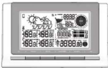
1 x base station
3×AA
UM-3 1.5V batteries
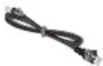
1 x USB cable
1 x adapter
WIND SENSOR
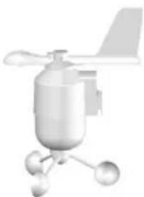
natural_image
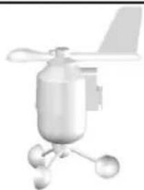
3D rendering of a propeller or fan with propellers and a small sphere, no visible text or symbols1 x wind sensor (1 x wind vane above and 1 x anemometer below)
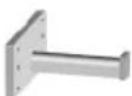
1 x sensor connector
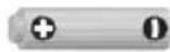
2 x AA UM-3
1.5V batteries
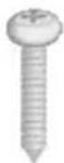
4 x screws
(Type A)
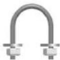
1 x round
U-bolt
TEMPERATURE & HUMIDITY SENSOR
natural_image
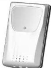
White rectangular electronic device with a circular vent and ventilation slots (no visible text or symbols)1 x temperature / humidity sensor
natural_image
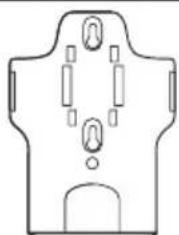
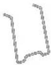
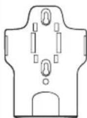
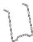
Simple line drawing of a symmetrical mechanical or electrical component with no text or symbols1 x wall mount bracket
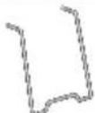
1 x table stand
2 x AAA UM-4
1.5V battery
RAIN GAUGE
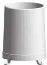
natural_image
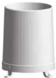
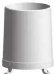
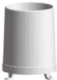
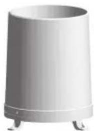
Exterior view of a cylindrical metal trash bin with three legs (no text or symbols visible)1 x rain collector
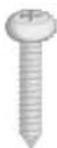
4 x screws
(Type B)
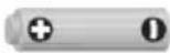
2 x AA UM-3
1.5V batteries
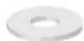
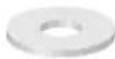
6 x washers
ACCESSORIES - SENSORS
This product can work with up to 3 sensors at any one time to capture outdoor temperature, relative humidity or UV readings in various locations.
Visit our website weather.oregonscientific.com for more about accessory sensors.
* Features and accessories will not be available in all countries.
OVERVIEW
TOP VIEW
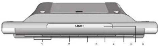
- UP / DOWN: Increase/decrease values of the selected setting; toggle to browse outdoor channels, toggle to browse the time history
- MODE: Switch between the different display modes/settings; set clock; set altitude; activate auto-scan, press to exit the history mode
- MAX / MIN: Read the max/min memory readings; clear readings
- SELECT: Switch between the different areas
- UNIT: Select unit of measurement
- LIGHT: Activate backlight
BACK VIEW
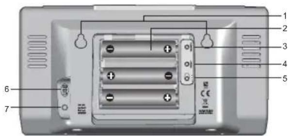
- Wall mount holes
- Battery compartment
-
SEARCH: Searches for sensors or for the radio controlled clock signal
-
RESET: Returns unit to default settings
- EU / UK switch: Select the nearest radio signal (WMR89 only)
- Micro USB socket
- AC adapter socket
LCD DISPLAY
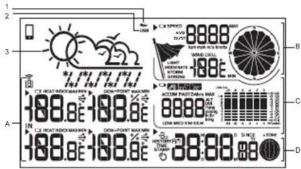
- : No main power supply
- USB: indicates a successful USB connection
- Weather forecast
A. Temperature/Humidity/Heat index/Dew point Area
B. Wind speed/Wind direction/Wind chill area
C. Barometer/UV/Rainfall area
D. Clock/Calendar/Moon phase/History area
A. Temperature/humidity/heat index/dew point area
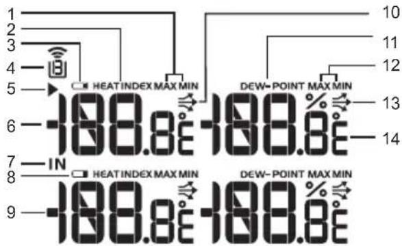
- MAX/MIN temperature
- HEAT INDEX
- Outdoor sensor low battery display
- Remote sensor channel indicator
- Select indicator
- Outdoor temperature reading (C°/F°)
- Indoor temperature indicator
- Main unit battery low
- Indoor temperature reading (C°/F°)
- Temperature trend
- DEW POINT
- MAX/MIN humidity
- Humidity trend
- Humidity reading
B. Wind speed/wind direction/wind chill area
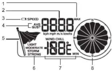
- MAX wind speed memory display
- Wind speed reading (m/s, knots, kph or mph)
- Outdoor wind sensor low battery display
- Wind speed indicator (AVG/GUST)
- Wind speed level indicator
- Wind speed level description
- Minimum wind chill display
- Wind direction indicator
C. Barometer/UV/Rainfall Area
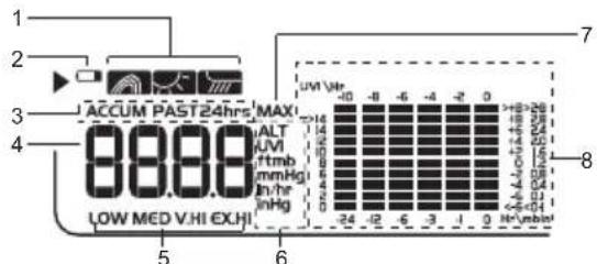
- Barometer/UV/rainfall reading indicator
- Outdoor UV/rain sensor low battery display
- ACCUM/PAST 24hrs – displays accumulative/past 24 hours rainfall
- Barometer/UV/rainfall readings
- UV level indicator
- Barometric pressure/UV/rainfall units display
- MAX barometer/UV/rainfall display
- Barometric pressure/UV/rainfall historical bar chart display
D. Clock/calendar/moon phase area
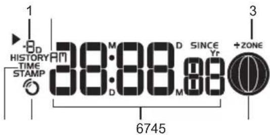
- History mode display
- AM/PM
- Time zone offset
- Timestamp indicator
- Clock signal reception indicator
- Time/date/calendar
- Moon phase
WIND SENSOR
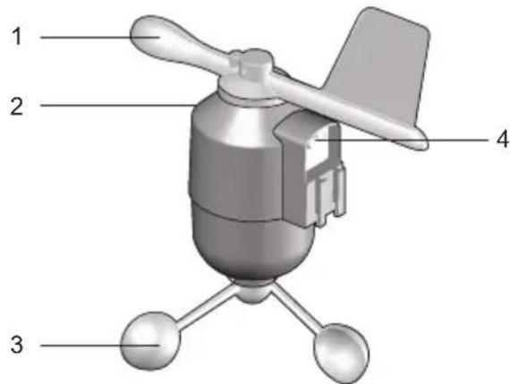
- Wind direction
-
Wind vane casing
-
Anemometer
- Solar power socket
RAIN GAUGE

- Rain gauge
- Battery compartment
- RESET button
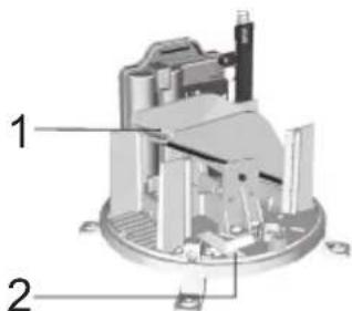
- Funnel
- Indicator
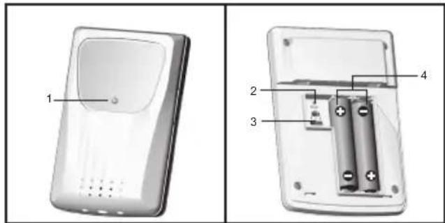
OUTDOOR TEMPERATURE / HUMIDITY SENSOR
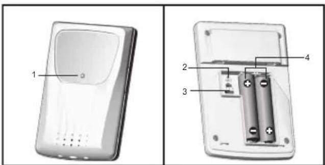
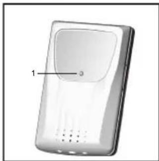
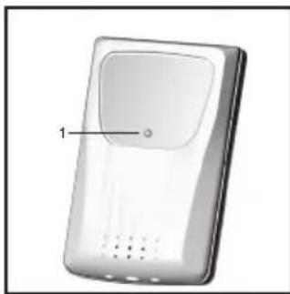
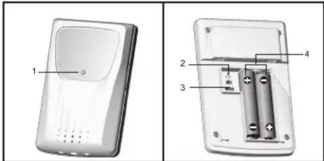
- LED status indicator
- RESET hole
- CHANNEL switch
- Battery compartment
GETTING STARTED
NOTE Install batteries in the remote sensors before the base station matching the polarities (+ and -).
NOTE Use alkaline batteries for longer usage and consumer grade lithium batteries in temperatures below freezing.
SET UP REMOTE WIND SENSOR
The wind sensor takes wind speed and direction readings. The sensor is battery operated. It is capable of transmitting data to the base station wirelessly within an approximate operating range of 100 meters (328 feet).
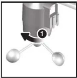
To insert batteries:
natural_image
Mechanical component diagram showing a rotating arm with three spheres connected by rods (no text or symbols)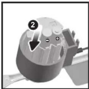
natural_image
Close-up of a mechanical component with a circular head and internal structure, showing a downward arrow and plus/minus signs (no readable text or symbols)- Unscrew the anemometer from the wind sensor carefully.
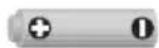
- Insert batteries matching the polarities (+ / -) and replace the anemometer.
SET UP REMOTE TEMPERATURE / HUMIDITY SENSOR
The remote sensor can collect data from up to 3 channels.
To set up the remote sensor:
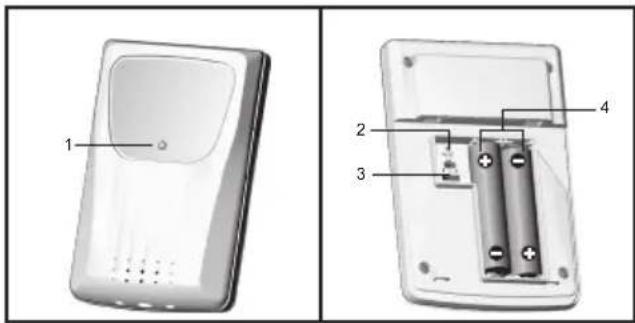
- Slide open the battery door.
- Slide channel switch to select a channel (1/2/3). Use a different channel for each sensor.
- Insert the batteries, matching the polarities (+ / -).
- Close the battery door.
SET UP RAIN GAUGE
The rain gauge collects rain and takes rainfall readings. The sensor can remotely transmit data to the base station.
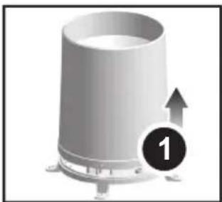
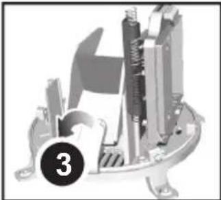
To set up the rain gauge:
natural_image
3D rendering of a cylindrical mechanical component with a numbered label '1' and an upward arrow, no readable text or symbols.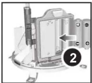
natural_image
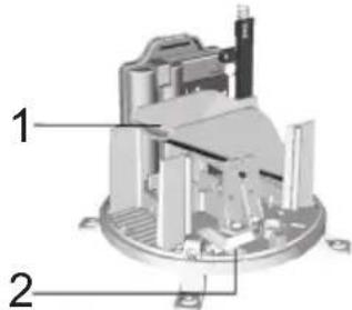
Mechanical assembly diagram showing a component with a labeled arrow and numbered marker (2), no readable text or symbols present.- Remove screws and slide the cover off in an upwards motion.
- Insert the batteries (2 x UM-3 / AA), matching the polarities (+ / -).
natural_image
Mechanical assembly diagram showing a clamping mechanism with no visible text or symbols- Remove the fibre tape.
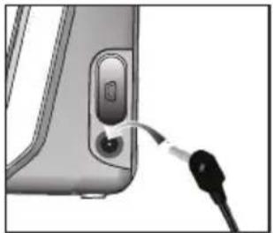
SET UP BASE STATION
NOTE Install batteries in the remote sensors before the base station matching the polarities (+ and -).
natural_image
Close-up of a device's cable being inserted into a port, showing a black connector (no text or symbols visible)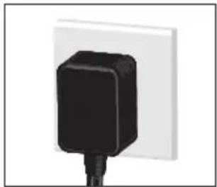
natural_image
Close-up of a black electrical plug with a white wall (no text or symbols visible)For continuous use, please install the AC adaptor. The batteries are for back-up use only.
NOTE Make sure the adaptor is not obstructed and is easily accessible to the unit.
NOTE The base station and adaptor should not be exposed to wet conditions. No objects filled with liquid, such as vases, should be placed on the base station and adaptor.
To completely disconnect from power, unplug adaptor from the mains.
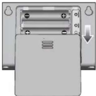
To insert batteries:
natural_image
Close-up of a battery pack with two terminals and a downward arrow indicating a drop (no text or symbols)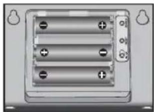
natural_image
Close-up of a battery pack with three batteries and two terminals (no visible text or symbols)- Slide open the battery door.
- Insert the batteries, matching the polarities (+ / -).
- Close the battery door.
NOTE Do not use rechargeable batteries. It is recommended that you use alkaline batteries with this product for longer performance.
NOTE Batteries should not be exposed to excessive heat such as sunshine or fire.
The battery icon indicator appears in the following areas:
| AREA MEANING | |
| Weather Forecast Area | It displays when the AC adaptor is disconnected. |
| Temperature or Humidity Area | Low battery in the main unit or outdoor sensor for displayed channel. |
| Wind Speed / Wind Direction / Wind Chil Area | Low battery in wind sensor. |
| UVI / Barometer / Rainfall Area | Low battery in UV/Rain sensor. |
MOUNTING/PLACING OF SENSORS
WIND SENSOR
Make sure the wind sensor is connected to the base station before installation.
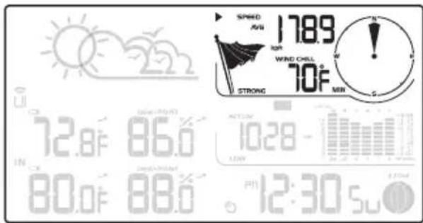
To check the connection:
Press SELECT until the selected area icon is in the top right display area.
- Wind speed: Gently rotate the wind vane and confirm a numerical reading on the base station, e.g.1789
- Wind direction indicator. Move the direction of the wind indication and verify the icon moves in the same direction ⚡️
The sensor should be positioned in an open area away from trees or other obstructions.
To install the wind sensor:
natural_image
Mechanical assembly diagram showing a lever mechanism with motion arrows (no text or symbols)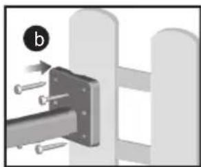
natural_image
Mechanical assembly diagram showing a bracket with bolts and a circular indicator labeled 'b' (no text or symbols on the diagram itself)Secure the sensor connector in the desired location:
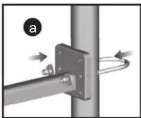
a. Align the back of the sensor connector to an existing pole. Secure in place by inserting the ends of the U-bolt into the holes on the sensor connector and securing it with washers and bolts.
OR
b. Insert 4 type A screws into the holes of the sensor connector. Screw firmly into place, i.e., fence.
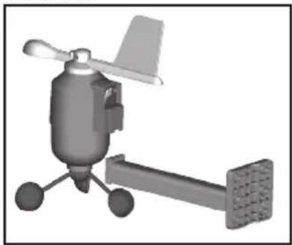
Slide wind vane onto the smaller end of the sensor connector.
natural_image
3D rendered mechanical component with propeller and mounting bracket (no text or symbols)IMPORTANT Make sure the wind sensor points to north in order to record accurate readings.
TEMPERATURE / HUMIDITY SENSOR
Make sure the temperature/humidity sensor is connected to the base station before installation.
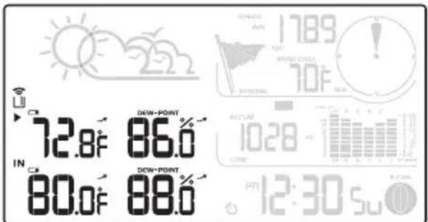
To check the connection:
- Press SELECT until the selected area icon is in the bottom left display area.
- Press UP / DOWN to select channel 1 📊 and verify a numerical reading.
To install the temperature/humidity sensor:
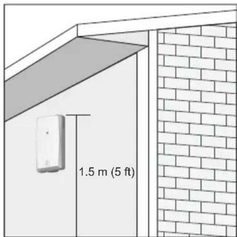
TIP Ideal placements for the sensor would be in any location on the exterior of the home at a height of not more than 1.5 meters (5 feet) and which can shield it from direct sunlight or wet conditions for an accurate reading.
natural_image
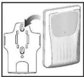
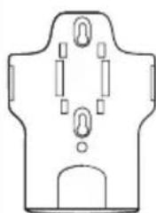
Diagram showing a device with a plug inserted into a housing and a separate device with ventilation slots (no text or symbols)Secure the sensor in the desired location using the wall mount bracket or table stand.
RAIN GAUGE
The base station and rain gauge should be positioned within an effective range: about 100 meters (328 feet) in an open area.
The rain gauge should be mounted horizontally about 1 meter (3 feet) from the ground in an open area away from trees or other obstructions to allow rain to fall naturally for an accurate reading.
Make sure the rain gauge is connected to the base station before installation.
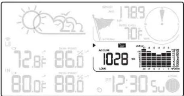
To check the connection:
- Press SELECT until the selected area icon is in the middle right display area.
- Press MODE repeatedly until hot-lays.
- Tilt the tipping funnel on the rain gauge several times, wait for a few seconds and then verify a numerical reading on the base station.
If no reading displays, press the SEARCH button on the back of the base station to initiate a wireless sensor search.
To ensure a level plane:
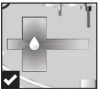
Put a few drops of water on the cross at the base of the funnel to check the horizontal level.
natural_image
Pure electrical circuit lines without any symbols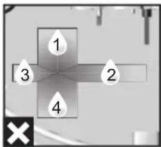
Water will pool to the center of the cross when the rain gauge is level.
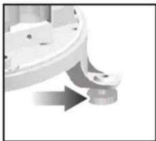
If water remains on 1-4, the gauge is not horizontal. If necessary, adjust the level using the screw.
natural_image
Close-up of a mechanical component with a curved arrow indicating rotation or movement (no visible text or symbols)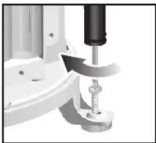
natural_image
Close-up of a mechanical assembly with a tool and base mount (no visible text or symbols)NOTE For best results, ensure the base is horizontal to allow maximum drainage of any collected rain.
TIP Press RESET button on back of the base station to erase all testing data.
BACKLIGHT
Press LIGHT to activate the backlight for 5 seconds.
CLOCK RECEPTION
This product is designed to synchronize its calendar clock automatically once it is brought within range of a radio signal:
WMR89:
• EU: DCF-77 signal: within 1500 km (932 miles) of Frankfurt, Germany.
- UK: MSF-60 signal: within 1500 km (932 miles) of Anthorn, England.
Slide the EU/UK switch to the appropriate setting based on your location. Press RESET whenever you change the selected setting.
WMR89A:
- WWVB-60 signal: within 3200 km (2000 miles) of Fort Collins Colorado.
The reception icon will blink when it is searching for a signal. If the radio signal is weak it can take up to 24 hours to get a valid signal reception. Indicates the status of the clock reception signal.
| ICON MEANING | |
 | Time is synchronized.Receiving signal is strong. |
 | Time is not synchronized.Receiving signal is weak. |
To enable (and force a signal search when previous search was unsuccessful)/disable the clock radio reception:
- Press SELECT repeatedly to navigate icon to the clock/calendar/moon phase area.
- Press and hold SEARCH. 🔒 displays when it is enabled.
NOTE For best reception, place the base station on a flat, non-metallic surface near a window in an upper floor of your home. Place the antenna away from electrical appliances do not move the antenna when searching for a signal.
CLOCK / CALENDAR
To set the clock manually, disable the clock signal reception first
To manually set the clock:
(You only need to set the clock and calendar if you have disabled the clock radio reception.)
- Press SELECT repeatedly to navigate icon to the clock/calendar/moon phase area.
- Press and hold MODE to change the clock setting. The setting part blinks.
- Press UP / DOWN to increase/decrease the setting value.
- Press MODE to confirm.
- Repeat steps 3 – 4 to set the time zone offset hour (+/-23 hours), 12/24 hour format, hour, minute, year, date/month format, month, date, weekday language and hemisphere option for moon phase.
Time zone offset sets the clock +/- 23 hours from the received clock signal time. If you have deactivated the clock signal reception, do not set a value for time zone.
NOTE If you enter +1 in the time zone setting, the clock displays 1 hour ahead of your set regional time.
If you are in the US (WMR89A only) set the clock to:
PA for Pacific time
MO for Mountain time
CE for Central time
EA for Eastern time
NOTE The weekday is available in English (E), German (D), French (F), Italian (I), Spanish (S) or Russian (R).
To change the clock display:
- Press SELECT repeatedly to navigate icon to the clock/calendar/moon phase area.
-
Press MODE to toggle between:
-
Clock with seconds
- Clock with weekday
- Calendar
MOON PHASE
The Calendar must be set for this feature to work (see Clock / Calendar section).
 | New Moon |  | Full Moon |
| [0A26] | Waxing Crescent |  | Waning Gibbous |
| [7D5Z] | First quarter |  | Third quarter |
| [SZTH] | Waxing Gibbous |  | Waning Crescent |
NOTE The moon phase displays in opposite orientation if you are in southern hemisphere.
AUTO SCANNING FUNCTION
To activate the outdoor temperature and humidity auto-scan function:
- Press SELECT repeatedly to navigate icon to the Outdoor temperature reading in the or Humidity area.
- Press and hold MODE to activate auto-scan. The temperature and humidity display will scroll from indoor to channel 1 – 3.
- Press any key to stop the auto-scan.
NOTE Channel 1 is used for the outdoor temperature and humidity sensor. Use other channels for additional temperature and humidity sensors.
WEATHER FORECAST
This product forecasts the next 12 to 24 hours of weather forecast within a 30-50 km (19-31 mile) radius.
Weather forecast area
| ICON DESCRIPTION | |
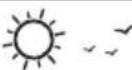 | Sunny |
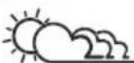 | Partly cloudy |
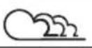 | Cloudy |
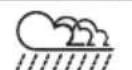 | Rainy |
 | Snowy |
TEMPERATURE AND HUMIDITY
The weather station displays indoor and outdoor readings for:
- Temperature/Relative humidity (current/maximum/minimum)
- Trend line
• Wind chill/Dew point level/Heat index
The weather station can connect up to 3 remote sensors.
indicates the current sensor viewing.
- Temperature / relative humidity (current / maximum / minimum)
- Trend line
- Wind chill (current / minimum) and dew point level (current / maximum / minimum)
The timestamp records the date and time when storing the MAX/MIN temperature record and humidity readings in memory.
To select the temperature measurement unit:
Press UNIT to select °C / °F.
NOTE The unit of all temperature related displays will be changed simultaneously.
To view current temperature, heat index and MAX/MIN readings:
- Press SELECT repeatedly to navigate icon to the temperature/heat index area.
- Press UP / DOWN to select the channel in outdoor temperature area.
- Press MODE repeatedly to toggle between the temperature/heat index displays.
- Press MAX / MIN to toggle between current / MAX / MIN readings.
To view humidity, MAX/MIN and dew point readings:
- Press SELECT repeatedly to navigate icon to the humidity/dew point area.
- Press UP / DOWN to select the channel in outdoor humidity area.
- Press MODE repeatedly to toggle between the humidity/ dew point displays.
- Press MAX / MIN to toggle between current/MAX/ MIN readings.
The timestamp is displayed accordingly in the clock area.
To clear the memories and timestamp for the temperature, humidity, heat index and dew point readings:
In the temperature or humidity area, press and hold MAX / MIN to clear the readings as current data.
NOTE The heat index provides an indication on how hot it feels based on air temperature and relative humidity.
NOTE The dew point advises at what temperature condensation will form.
TEMPERATURE AND HUMIDITY TREND
The trend lines are shown next to the temperature and humidity readings. The trend is shown as follows:
The base station provides wind speed and wind direction information.
To read the wind direction, find the compass point the pointing to.
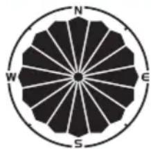
The timestamp records the date and time when storing the wind speed readings.
To select the wind speed unit:
- Press SELECT repeatedly to navigate ▶ icon to the wind speed/wind direction/wind chill area.
- Press UNIT to switch between:
• Kilometers per hour (kph)
• Miles per hour (mph)
- Meters per second (m/s)
- Knots (knots)
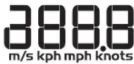
The wind level is shown by a series of icons:
| ICON LEVEL DESCRIPTION | |
| N/A < 0.9 meters/s (<1.5 km/s) | |
| Light 0.9-3.6 meters/s (1.5-2.4 km/s) | |
| Moderate 3.6-11.2 meters/s (2.4-18km/s) | |
| Strong 11.2-24.4 meters/s (18-39.2 km/s) | |
| Storm >24.4 meters/s (>39.2 km/s) | |
ICON LEVEL DESCRIPTION
To view the maximum wind speed and minimum wind chill readings:
- Press SELECT repeatedly to navigate icon to the wind speed/wind direction/wind chill area.
- Press MAX / MIN to toggle between current/MAX wind speed and current/MIN wind chill readings.
The timestamp of when maximum wind speed or the minimum wind chill recorded is displayed accordingly.
To clear minimum wind chill reading/maximum wind speed reading:
- Press SELECT repeatedly to navigate icon to the wind speed/wind direction/wind chill area.
- Press MAX / MIN repeatedly until minimum wind chill reading or maximum wind speed reading displays.
- Press and hold MAX / MIN to clear the readings as current data.
The wind chill factor is based on the combined effects of temperature and wind speed. Wind chill reading display is calculated solely from channel 1 sensor.
BAROMETER/UV/RAINFALL
The weather station works with one UV sensor and one rain gauge. The station is capable of storing and displaying the hourly history data for the last 10 hours of UV index, and 24 hours of rainfall and barometric pressure readings.
| BAROMETER | UV | RAINFALL |
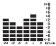 | 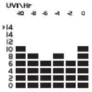 | 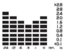 |
The bar chart display shows the current and historical data for the barometric pressure, UV index and rainfall readings.
The number shown in the horizontal axis (Hr) indicates how long ago each measurement was taken (e.g. 3 hours ago, 6 hours ago, etc.). The bar represents the measurement taken for that specific 1 hour period. E.g., if it is 10:30 pm now, the bar plotted directly above -1 shows the reading recorded from 9 to 10 pm and -6 shows the reading recorded earlier in the evening, between 4pm-5pm.
To view the barometer/UV/rainfall readings:
-
Press SELECT repeatedly to navigate icon to the barometer/UV/rainfall area.
-
Press MODE to toggle between barometer/UV/rainfall readings. The corresponding icon displays.
| BAROMETER UV | RAINFALL | |
 |  |  |
To select the measurement unit for the barometer or rainfall readings:
In the barometer/UV/rainfall area, press UNIT to switch between:
- Barometer: Millimeters of mercury (mmHg), inches of mercury (inHg), millibars per hectopascal (mb).
- Rainfall: Millimeters (mm), inches (in), recorded for that hour.
NOTE The bar chart provides a quick comparison between the records of the past 24 hours, the vertical axis cannot convert from inches to mm. Changing the measurement unit will have no effect on the bar graph display.
BAROMETER
To set the altitude level compensation for the Barometer readings:
- Press SELECT repeatedly to navigate icon to the barometer/UV/rainfall area.
- Press MODE repeatedly to select
- Press and hold MODE to enter the altitude setting.
- Press UP / DOWN to increase/decrease the setting value.
- Press MODE to confirm the setting.
UV INDEX
The UV index levels are as follows:
| UV INDEX DANGER LEVEL ICON | ||
| 0-2 Low | LOW | |
| 3-5 Moderate | MED | |
| 6-7 High | HI | |
| 8-10 | Very high | V.HI |
| 11 and above | Extremely high | EX.HI |
To view the maximum UV reading:
- Press SELECT repeatedly to navigate icon to the barometer/UV/rainfall area.
- Press MODE repeatedly to select
- Press MAX / MIN to toggle between current/MAX UV index display.
The timestamp of when maximum UV was recorded is displayed accordingly in the clock area.
To clear maximum UV reading:
- Press SELECT repeatedly to navigate icon to the barometer/UV/rainfall area.
- Press MODE repeatedly to select UV display.
- Press and hold MAX / MIN to clear the readings as current data..
RAINFALL
To view the recorded rainfall of the current hour or last 24 hours:
- Press SELECT repeatedly to navigate icon to the Barometer/UV/Rainfall area.
- Press MODE repeatedly to select
- Press MAX / MIN repeatedly to toggle between current hour, past 24 hours or accumulated rainfall readings.
REVIEW STORED DATA
The main unit stores up to 7 days data. The data includes:
- Indoor/outdoor temperature (MAX, MIN)
- Indoor/outdoor humidity (MAX, MIN)
• AVG wind speed, GUST - Wind chill
- Air pressure
• Rainfall/Total rainfall/Accumulate rainfall - Max. UV index
- Moon phase
To review the data history:
- Press SELECT repeatedly to navigate ▶ Icon to the clock area.
- Press DOWN to review the history. The screen displays

While the base station is in history mode:
- Press UP / DOWN to review the history at different time intervals.
-OR-
Press and hold UP / DOWN to review the history at different time intervals quickly.
The record displays in 1 hour interval.
- Press SELECT to select desired section.
- Press MAX / MIN or MODE in desired section to review different information.
To exit the history mode
- Press SELECT repeatedly to navigate icon to the clock area. Then press MODE.
NOTE
- When reviewing the history, it displays the nearest hour record. eg. When the current time is 11:05 am, the latest history for review is 11:00 am. When the current time is 12:59 pm, the latest history for review is 12:00 pm.
• Each daily record starts at 12:00 am. If the current time is 12:30 am, the screen displays when reviewing the history before 12:00 am.
UPLOAD DATA TO PC SOFTWARE
NOTE Download and install the software before uploading the data.
NOTE The USB is used for uploading data only. It does not support battery charging
Visit our website weather.oregonscientific.com for the PC software.
natural_image
Close-up of a device's cable and connector with a USB cable (no text or symbols visible)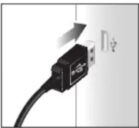
natural_image
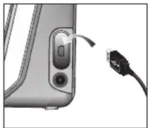
Close-up of a black USB cable with a white connector, showing a lightning bolt symbol (no text or labels)- Plug one end of the USB cable into the base station's USB port and the other end into the PC's USB port. The main unit displays USB
- Uploading will start immediately.
NOTE This product should be supplied by an identical USB port complying with the requirements of Limited Power Source.
RESET
Press RESET to reset to the default settings.
SPECIFICATIONS
BASE STATION
L x W x H 180 x 110 x 47mm (7.1 x 4.3 x 1.9 in)
Weight 286 g (10 ounces) without batteries
Battery 6V adaptor; 3 x UM-3 (AA) 1.5V
INDOOR BAROMETER
Barometer unit mb, inHg and mmHg
Measuring range 700 - 1050mb/hPa
Accuracy +/- 7 mb/hPa
Altitude setting Sea level
User setting for compensation
Weather display Sunny, Partly Cloudy, Cloudy, Rainy and Snowy
Memory Historical data and bar chart for last 24hrs
INDOOR TEMPERATURE
Temp. unit °C / °F
Operating range 0°C to 50°C (-32°F to 122°F)
Accuracy 0^ - 40^: +/- 1^ (+/- 2.0^)
40^-50^:+/-2^(+/-4.0^)
Memory Current, Min and Max temp.
INDOOR RELATIVE HUMIDITY
| Operating range | 25% to 90% |
| Accuracy | 25% - 40%: +/- 7% |
| 40% - 80%: +/- 5% | |
| 80% - 90%: +/- 7% | |
| Memory | Current, Min and Max |
RADIO-CONTROLLED / ATOMIC CLOCK
| Synchronization | Auto or disabled |
| Clock display | HH:MM:SS |
| Hour format | 12hr AM/PM or 24hr |
| Calendar | DD/MM or MM/DD |
| Weekday in 6 languages | (E, G, F, I, S, R) |
REMOTE WIND SENSOR UNIT
| L x W x H | 178 x 76 x 214 mm(7 x 3 x 8.4 inches) |
| Weight | 100 g (3.53 ounces) without battery |
| Wind speed unit | m/s, knots, kph, mph |
| Speed accuracy | 2 m/s ~ 10 m/s (+/- 3 m/s)10 m/s ~ 56 m/s (+/- 10%) |
| Direction accuracy | 16 positions |
| Transmission of wind speed signal | Approx. every 56 seconds |
| Memory | Max wind speed |
| Power | 2 x UM-3 (AA) 1.5V batteries |
OUTDOOR TEMPERATURE / HUMIDITY UNIT
| L x W x H | 92 x 60 x 20 mm(3.6 x 2.4 x 0.79 in) |
| Weight | 62 g (2.22oz) without batteries |
| Humidity range | 5% to 95% |
| Temp. unit °C / °F | |
| Temperature outdoor range | -30°C to 60°C (-22°F to 140°F) |
| RF frequency | 433 MHz |
| Range | Up to 100 meters (328 feet)with no obstructions |
| Transmission | Approx. every 102 seconds |
| Channel no. | 3 |
| Power | 2 x UM-4 (AAA) 1.5 V batteries |
REMOTE RAIN GAUGE
| L x W x H | 114 x 114 x 145 mm(4.5 x 4.5 x 5.7 inches) |
| Weight | 241 g (8.5 oz) without batteries |
| Rainfall unit | Mm and in |
| Range | 0 mm – 9999 mm |
| Accuracy | < 15 mm: +/- 1 mm15 – 9999 mm: +/- 10% |
| Memory Past 24 hrs, hourly from lastmemory reset | |
| Power | 2 x UM-3 (AA) 1.5 V batteries |
PRECAUTIONS
- Do not subject the unit to excessive force, shock, dust, temperature or humidity.
- Do not cover the ventilation holes with any items such as newspapers, curtains etc.
- Do not immerse the unit in water. If you spill liquid over it, dry it immediately with a soft, lint-free cloth.
- Do not clean the unit with abrasive or corrosive materials.
- Do not tamper with the unit's internal components. This invalidates the warranty.
- Only use fresh batteries. Do not mix new and old batteries.
- Images shown in this manual may differ from the actual display.
- When disposing of this product, ensure it is collected separately for special treatment and not as household waste.
- Placement of this product on certain types of wood may result in damage to its finish for which Oregon Scientific will not be responsible. Consult the furniture manufacturer's care instructions for information.
- The contents of this manual may not be reproduced without the permission of the manufacturer.
- Do not dispose old batteries as unsorted municipal waste. Collection of such waste separately for special treatment is necessary.
- Please note that some units are equipped with a battery safety strip. Remove the strip from the battery compartment before first use.
NOTE The technical specifications for this product and the contents of the user manual are subject to change without notice.
NOTE Features and accessories will not be available in all countries. For more information, please contact your local retailer.
ABOUT OREGON SCIENTIFIC
Visit our website www.oregonscientific.com to learn more about Oregon Scientific products.
For any enquiry, please contact our Customer Services at info@oregonscientific.com.
Oregon Scientific Global Distribution Limited reserves the right to interpret and construe any contents, terms and provisions in this user manual and to amend it, at its sole discretion, at any time without prior notice. To the extent that there is any inconsistency between the English version and any other language versions, the English version shall prevail.
EU-DECLARATION OF CONFORMITY
Hereby, Oregon Scientific, declares that Full Wireless Weather Station Kit with USB upload (model: WMR89/WMR89A) is in compliance with the essential requirements and other relevant provisions of Directive 1999/5/EC. A copy of the signed and dated Declaration of Conformity is available on request via our Oregon Scientific Customer Service.


COUNTRIES RTTE APPROVAL COMPLIED
All EU countries, Switzerland CH
and Norway N
FCC STATEMENT
This device complies with Part 15 of the FCC Rules. Operation is subject to the following two conditions: (1) This device may not cause harmful interference, and (2) This device must accept any interference received, including interference that may cause undesired operation.
WARNING Changes or modifications not expressly approved by the party responsible for compliance could void the user's authority to operate the equipment.
NOTE This equipment has been tested and found to comply with the limits for a Class B digital device, pursuant to Part 15 of the FCC Rules. These limits are designed to provide reasonable protection against harmful interference in a residential installation.
This equipment generates, uses and can radiate radio frequency energy and, if not installed and used in accordance with the instructions, may cause harmful interference to radio communications. However, there is no guarantee that interference will not occur in a particular installation. If this equipment does cause harmful interference to radio or television reception, which can be determined by turning the equipment off and on, the user is encouraged to try to correct the interference by one or more of the following measures:
- Reorient or relocate the receiving antenna.
- Increase the separation between the equipment and receiver.
- Connect the equipment into an outlet on a circuit different from that to which the receiver is connected.
- Consult the dealer or an experienced radio/TV technician for help.
This Class B digital apparatus complies with Canadian ICES-3(B)/NMB-3(B)
DECLARATION OF CONFORMITY
The following information is not to be used as contact for support or sales. Please call our customer service number (listed on our website at www.oregonscientific.com), or on the warranty card for this product) for all inquiries instead.
We
Name: Oregon Scientific, Inc.
Address: 10778 SW Manhasset Dr.
Tualatin, Or 97062 USA
Telephone No.: 1-800-853-8883
declare that the product
Product No.: WMR89 / WMR89A
Product Name: Full Wireless Weather Station Kit with USB upload
Manufacturer: IDT Technology Limited
Address: Block C, 9/F, Kaiser Estate,
Phase 1, 41 Man Yue St.,
Hung Hom, Kowloon,
Hong Kong
DISPOSAL INFORMATION FOR USERS
Pursuant to and in accordance with Article 14 of the Directive 2012/19/EU of the European Parliament on waste electrical and electronic equipment (WEEE), and pursuant to and in
accordance with Article 20 of the Directive 2006/66/EC of the European Parliament on batteries and accumulators and waste batteries.
The barred symbol of the rubbish bin shown on the equipment indicates that, at the end of its useful life, the product must be collected separately from other waste.
Please note that the batteries/rechargeable batteries must be removed from the equipment before it is given as waste. To remove the batteries/accumulators refer to the specifications in the user manual. Therefore, any products that have reached the end of their useful life must be given to waste disposal centers specializing in separate collection of waste electrical and electronic equipment, or given back to the dealer when purchasing a new WEEE, pursuant to and in accordance with Article 14 as implemented in the country.
The adequate separate collection for the subsequent start-up of the equipment sent to be recycled, treated and disposal of in an environmentally compatible way contributes to preventing possible negative effects on the environment and health and optimizes the recycling and reuse of components making up the apparatus.
Abusive disposal of the product by the user involves application of the administrative sanctions according to the laws in force.
natural_image
3D rendering of a propeller with propeller blade and four wheels (no text or symbols)natural_image
White handheld mobile phone with rounded screen and ventilation slots (no visible text or symbols)natural_image
Simple line drawing of a symmetrical mechanical or architectural component with no text or symbolsnatural_image
Exterior view of a cylindrical metal trash bin with three legs (no text or symbols visible)- Imbuto
- Indicatore
TEMPERATURA ESTERNA/SENSORE DI UMIDITA'
natural_image
Illustration of a smartphone with a labeled component (1) and no visible text or symbols on the device itself.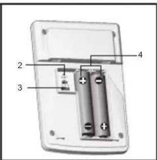
natural_image
Mechanical component diagram showing a rotating arm with three spheres connected by rods (no text or symbols)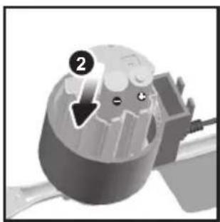
natural_image
Cross-sectional diagram of a mechanical component with internal structure and labeled point (2), no readable text or symbols present.IMPOSTARE LA TEMPERATURA REMOTA/SENSORE UMIDITA'
natural_image
3D rendering of a cylindrical mechanical component with an upward arrow and number 1 label (no text or symbols on the object itself)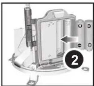
natural_image
Mechanical assembly diagram showing a device with a lever and labeled component (no readable text or symbols)natural_image
Mechanical assembly diagram showing a clamping mechanism with no visible text or symbolsnatural_image
Close-up of a device's cable being inserted into a port, showing the cable connector (no text or symbols visible)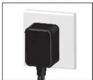
natural_image
Close-up of a black plastic electrical plug attached to a white wall (no text or symbols visible)natural_image
Close-up of a battery holder with buttons and a downward arrow indicating rotation (no text or symbols)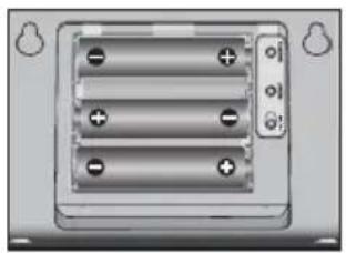
natural_image
Close-up of a battery pack with three batteries and one terminal, no visible text or symbolsnatural_image
Mechanical assembly diagram showing a lever mechanism with motion arrows (no text or symbols)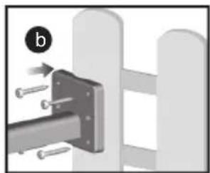
natural_image
Mechanical assembly diagram showing a bracket mounted on a vertical rod with bolts, no text or symbols presentnatural_image
3D rendering of a weathering helicopter with propeller and mounted sensor (no text or symbols visible)natural_image
Diagram showing a device with internal components and an external panel (no text or symbols)natural_image
Mechanical assembly diagrams showing a rotating component and a screw inserted into a housing (no text or symbols)natural_image
Close-up of a device's cable and connector with a USB cable (no text or symbols visible)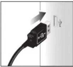
natural_image
Close-up of a black USB cable with a white connector, showing a directional arrow and partial symbol (no text or labels)natural_image
Illustration of a propeller with a propeller blade and three wheels (no text or symbols)natural_image
White rectangular electronic device with ventilation slots and a back panel (no visible text or symbols)natural_image
White cylindrical trash bin with three legs (no text or symbols visible)1 pluviomètre
4 vis
(de Type B)
2 piles AA UM-3 1.5 V
6 rondelles
natural_image
Two grayscale diagrams showing mechanical components with arrows indicating motion or force, no text or symbols present.natural_image
Two technical diagrams showing a cable being inserted into a device and connected to an electrical outlet (no text or symbols present)natural_image
Close-up of a battery holder with buttons and a downward arrow indicating a drop (no text or symbols)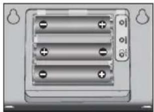
natural_image
Close-up of a battery pack with three batteries and one terminal, no visible text or symbolsnatural_image
Mechanical assembly diagram showing a metal bracket inserted into a wall with bolts, no text or symbols presentnatural_image
3D rendering of a weathering instrument with propeller and mounted sensor (no text or symbols visible)natural_image
Diagram showing a device with a handle and internal components, next to a rectangular device (no text or symbols)natural_image
Abstract grayscale diagram with a central droplet and cross-shaped elements, no visible text or symbols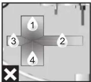
natural_image
Close-up of a mechanical component with a curved arrow indicating motion or force (no text or symbols visible)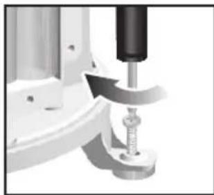
natural_image
Close-up of a mechanical measuring instrument with a spring scale (no visible text or symbols)natural_image
Close-up of a device's cable and connector with a USB cable (no text or symbols visible)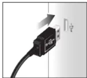
natural_image
Close-up of a black USB cable with a white connector, showing an arrow indicating direction (no text or symbols)natural_image
3D rendering of a propeller with propeller blades and control knob (no text or symbols)natural_image
White handheld device with a rounded top and ventilation slots (no visible text or symbols)natural_image
Exterior view of a cylindrical metal trash bin with three legs (no text or symbols)- Trichter
- Indikator
AUSSENTEMPERATUR / LUFTFEUCHTIGEITS-SENSOR
natural_image
Illustration of a mobile phone with a labeled screen and ventilation slots (no text or symbols beyond the label)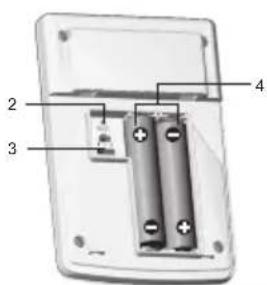
natural_image
Mechanical component diagram showing a rotating shaft with two spherical ends and a numbered arrow indicating rotation (no text or symbols)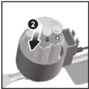
natural_image
Illustration of a cartoon character inside a mechanical device with a downward arrow, no text or symbols presentnatural_image
Illustration of a cylindrical industrial component with an upward arrow and number 1, no text or symbols present.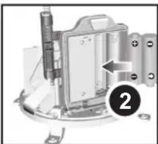
natural_image
Mechanical assembly diagram showing a component with a labeled arrow and numbered marker (2), no readable text or symbols present.natural_image
Mechanical assembly with metallic components and a numbered label (3) in the corner, no readable text or symbols present.natural_image
Close-up of a device's cable being inserted into a port (no text or symbols visible)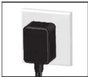
natural_image
Close-up of a black plastic electrical plug attached to a white wall (no text or symbols visible)natural_image
Close-up of a battery holder with buttons and a downward arrow indicating a drop (no text or symbols visible)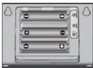
natural_image
Close-up of a battery pack with three batteries and three lead leads (no text or symbols visible)natural_image
Two mechanical diagrams showing a metal bracket with attached components and a close-up view of the same assembly (no text or symbols present)natural_image
3D rendering of a helicopter with propeller and mounted sensor array (no text or symbols)natural_image
Diagram showing a device with a door and a rectangular panel, no text or symbols presentnatural_image
Pure electrical circuit lines without any symbols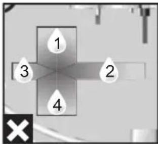
natural_image
Close-up of a mechanical component with a curved arrow indicating motion or force (no text or symbols visible)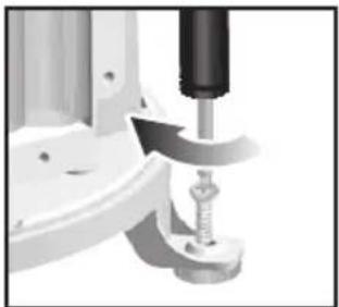
natural_image
Close-up of a mechanical assembly with a screw and clamped components (no visible text or symbols)natural_image
Close-up of a device's cable and connector with a USB cable (no text or symbols visible)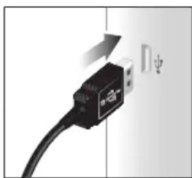
natural_image
Close-up of a USB cable with a switch and arrow indicating rotation (no text or symbols)1 x Estación base
3 x pilas AA/UM 1.5 V
1 x Cable USB
natural_image
3D rendering of a propeller with propeller blade and two spherical arms (no text or symbols)natural_image
White rectangular electronic device with ventilation slots and a back panel (no visible text or symbols)natural_image
Simple line drawing of a symmetrical mechanical or electrical component with no text or symbols1 x Soporte de pared
1 x Pie de apoyo
2 x Pilas AAA/UM 1.5 V
PLUVIÓMETRO
natural_image
Exterior view of a cylindrical metal trash bin with three legs (no text or symbols)- Embudo
- Indicador
SENSOR EXTERNO DE TEMPERATURA Y HUMEDAD
natural_image
Two grayscale diagrams showing a mechanical component before and after assembly, with numbered callouts (1 and 2) indicating steps of motion or assembly.natural_image
Mechanical assembly with spring-loaded components and a numbered label (3) in the corner, no readable text or symbols present.- Retire la cinta de fibra.
natural_image
Two technical diagrams showing a close-up of a device with a cable inserted into a wall and a plug inserted into a white socket (no text or symbols present)natural_image
Close-up of a battery pack with a button and indicator lights, showing internal components (no text or symbols)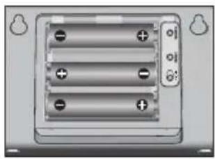
natural_image
Close-up of a battery pack with three leads and three power terminals (no visible text or symbols)natural_image
Mechanical assembly diagram showing a rotating shaft connected to a mounting bracket (no text or symbols)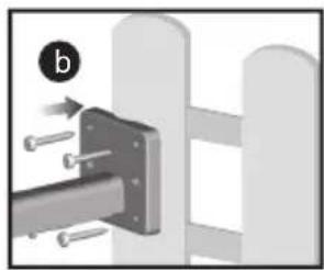
natural_image
Mechanical assembly diagram showing a bracket with bolts and a pin, no text or symbols presentnatural_image
3D rendering of a weathering helicopter with propeller and mounted sensor array (no text or symbols)IMPORTANTE
CONSEJO
natural_image
Diagram showing a device with a plug inserted into a housing and a separate device with a handle (no text or symbols present)natural_image
Pure electrical circuit lines without any symbols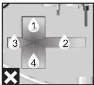
natural_image
Close-up of a mechanical component with a curved arrow indicating motion or force (no visible text or symbols)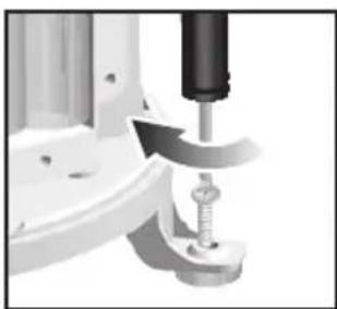
natural_image
Close-up of a mechanical assembly with a tool and screw (no visible text or symbols)NOTA
natural_image
Close-up of a computer monitor with a USB cable inserted, showing the right side of the screen (no text or symbols visible)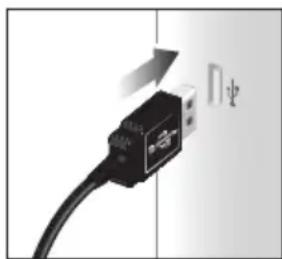
natural_image
Close-up of a black USB cable with a white connector, showing a curved arrow indicating rotation (no text or symbols)natural_image
3D rendering of a propeller with propeller blades and propeller base (no text or symbols)natural_image
Exterior view of a modern office building (no signage)natural_image
Simple line drawing of a symmetrical mechanical or architectural component with no text or symbols1 x suporte de montagem de parede
1 x suporte de
mesa
2 x baterias
AAA UM-4
1.5 V
PLUVIÔMETRO
natural_image
Simple 3D rendering of a cylindrical object with four legs, resembling a trash bin or container (no text or symbols visible)1 x Colector de chuva
- Funil
- Indicador
SENSOR DE TEMPERATURA EXTERIOR/UMIDADE
natural_image
Two technical diagrams showing a cylindrical component and a mechanical assembly with labeled parts (no text or symbols present)natural_image
Mechanical assembly diagram showing internal components and a numbered label (3), no readable text or symbols present.- Remova a fita de fibra.
natural_image
Two technical diagrams showing a device with a cable inserted into a socket and a plug inserted into a white wall (no text or symbols present)natural_image
Close-up of a battery pack with buttons and a downward arrow indicating a drop (no text or symbols)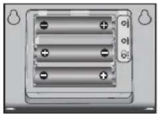
natural_image
Close-up of a battery pack with three leads and four terminals (no visible text or symbols)natural_image
Mechanical assembly diagram showing a lever mechanism with motion arrows (no text or symbols)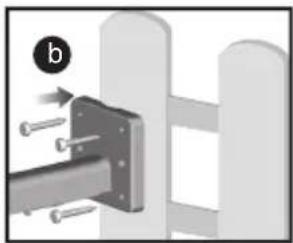
natural_image
Mechanical assembly diagram showing a bracket with bolts and a pin, no text or symbols presentnatural_image
3D rendering of a helicopter with propeller and mounted sensor array (no text or symbols)natural_image
Diagram showing a device with a plug and connector, connected to a rectangular device (no text or symbols present)natural_image
Two-panel diagram showing mechanical assembly steps: left panel shows a rotating component with arrows indicating motion; right panel shows a drill bit interacting with a screw (no text or symbols)natural_image
Close-up of a device's cable connector with a USB cable inserted, showing no text or symbols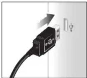
natural_image
Close-up of a black USB connector with a cable, showing a directional arrow and partial symbol (no text or labels)Remote Windsensor Unit 11
natural_image
3D rendering of a propeller or helicopter with propellers and control arms (no text or symbols visible)natural_image
White handheld electronic device with ventilation slots and a closed lid (no visible text or symbols)1
natural_image
Simple line drawing of a symmetrical mechanical or electrical component with no text or symbols1 x
muurmontagebeugel
1 tafelstand
2 AAA
UM-4 1.5V batterijen
REGENMETER
natural_image
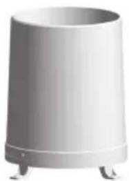
White cylindrical object with four legs, resembling a trash bin or container (no text or symbols visible)1 regenvanger
4 schroeven (Type B)
2 AA UM-3 1.5V batterijen
6 ringen
ACCESSOIRES - SENSOREN
-
Trechter
-
Indicator
BUITENTEMPERATUUR/
LUCHTVOCHTIGHEID SENSOR
- LED status-indicator
- RESET -opening
- CHANNEL schakelaar
- Batterijcompartiment
VOORBEREIDING
natural_image
Two grayscale diagrams showing mechanical components with arrows indicating motion or force, no text or symbols present.natural_image
Two technical diagrams showing a cylindrical component and a mechanical assembly with arrows indicating motion (no text or symbols present)natural_image
Mechanical assembly diagram showing a motor or gear assembly with no visible text or symbols- Verwijder de tape.
natural_image
Two technical diagrams showing a device with a cable inserted into a wall and a plug inserted into a white socket (no text or symbols present)natural_image
Close-up of a battery pack with buttons and a downward arrow indicating a change (no text or symbols)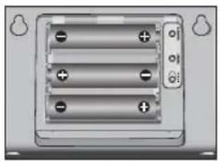
natural_image
Close-up of a battery pack with three batteries and two terminal labels (no text or symbols visible)natural_image
Mechanical assembly diagram showing a rotating rod connected to a bracket with a spring, no text or symbols present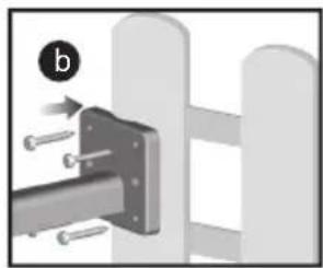
natural_image
Mechanical assembly diagram showing a bracket with bolts and a pin, no text or symbols presentnatural_image
3D rendered mechanical component with propeller and mounting bracket (no text or symbols)natural_image
Diagram showing a device with a plug and a separate device (no text or symbols present)natural_image
Abstract grayscale graphic with a central droplet and cross shape, no text or symbols present.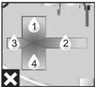
natural_image
Close-up of a mechanical component with a curved arrow indicating motion or force (no text or symbols visible)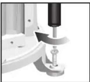
natural_image
Close-up of a mechanical device with a metallic component inserted, no visible text or symbolsbar
BAROMETER UV REGENVAL | Category | UVI \ Hr | Hr | |---|---|---| | 1 | -8 | 2.8 | | 2 | +8 | 2.8 | | 3 | +6 | 2.4 | | 4 | +4 | 2.0 | | 5 | +2 | 1.6 | | 6 | 0 | 1.2 | | 7 | -2 | 0.8 | | 8 | -4 | 0.4 | | 9 | -6 | 0.1 | | 10 | -8 | <0.1 | | 11 | -10 | In | The visual data is presented as a grid of black squares representing the frequency of UVI and Hr values for each category. The first row contains negative values (e.g., -24, -2, -6) and the second row contains positive values (e.g., +24, -2, -6).natural_image
Close-up of a device's cable and connector with USB cable (no text or symbols visible)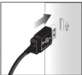
natural_image
Close-up of a black USB cable with a white connector, showing a directional arrow and a symbol (no text or labels)REMOTE WINDSENSOR UNIT
$$ \begin{array}{l} \mathrm{L} \times \mathrm{B} \times \mathrm{H} 1 7 8 \times 7 6 \times 2 1 4 \mathrm{mm} \ (7 \times 3 \times 2 1, 3 4 \mathrm{cm}) \end{array} $$
Indoor Temperature 10
1 x basstation
3 x AA UM-3
1.5 V batterier
1 x USB kabel
1 x adapter
VINDMÄTARE
natural_image
3D rendering of a propeller or fan device with propellers and a propeller blade (no text or symbols visible)natural_image
White handheld device with a rounded top and two small buttons at the bottom (no visible text or symbols)natural_image
Simple line drawing of a symmetrical mechanical or architectural component with no text or symbolsnatural_image
White cylindrical object with three legs, resembling a trash bin or waste can (no text or symbols visible)1 x Regnsamlare
4 x skruvar (Typ B)
2 x AA UM-3
1.5 V batterier
6 x skruvar
TILLBEHÖR - GIVARE
- Regnmätare
- Batterifack
- RESET (ÄTERSTÄLLNINGS) -knapp
- Tratt
- Indikator
O UTOMHUS TEMPERATUR/LUFTFUKTIGHETSGIVARE

- LED-statusindikator
- RESET (ÅTERSTÄLLNINGS) -hål
- CHANNEL (KANAL) -väljare
- Batterifack
KOMMA IGÅNG
natural_image
Mechanical component diagram showing a rotating arm with three spherical joints (no text or symbols)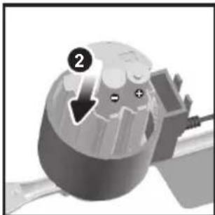
natural_image
Illustration of a mechanical component with a circular head and internal structure, no visible text or symbolsnatural_image
Illustration of a cylindrical industrial component with an upward arrow and number 1, no text or symbols present.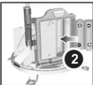
natural_image
Mechanical assembly diagram showing a device with labeled components and an arrow pointing to a component (no readable text or symbols)natural_image
Mechanical assembly diagram showing a bracket with springs and a numbered label (3) in the corner, no readable text or symbols present.- Ta bort fibertejp.
STÄLLA IN BASSTATIONEN
natural_image
Close-up of a device's cable being inserted into a port (no text or symbols visible)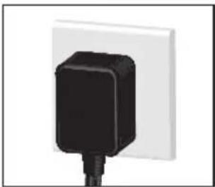
natural_image
Close-up of a black electrical plug inserted into a white wall socket (no text or symbols visible)natural_image
Close-up of a battery pack with a downward arrow indicating a drop or change (no text or symbols visible)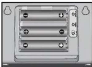
natural_image
Close-up of a battery pack with three leads and two terminals (no visible text or symbols)natural_image
Mechanical assembly diagram showing a lever mechanism with motion arrows (no text or symbols)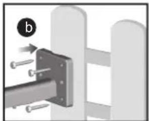
natural_image
Mechanical assembly diagram showing a bracket with bolts and a pin, no text or symbols presentnatural_image
3D rendering of a weathering instrument with propeller and mounting bracket (no text or symbols)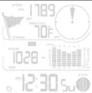
Kontrollera anslutning:
natural_image
Diagram showing a device with a labeled component and its corresponding view (no text or symbols present)Kontrollera anslutning:
natural_image
Pure electrical circuit lines without any symbols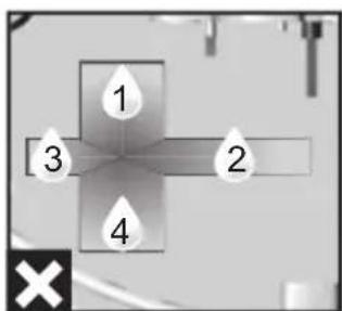
natural_image
Close-up of a mechanical component with a curved arrow indicating motion or force (no visible text or symbols)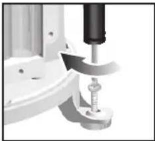
natural_image
Close-up of a mechanical component with a curved arrow indicating motion or force, no visible text or symbols▶ icon to the wind speed/wind direction/wind chill area.
natural_image
Close-up of a device's cable and connector with a USB cable (no text or symbols visible)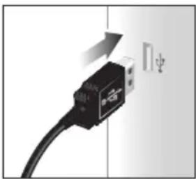
natural_image
Close-up of a black USB cable with a white connector, showing a directional arrow and partial symbol (no text or labels)natural_image
White rectangular electronic device with a closed lid and ventilation slots (no visible text or symbols)1×溫度/濕度感應器
natural_image
Simple line drawing of a symmetrical mechanical or architectural component with no text or symbols1×掛牆支架
1×座台支架
2×AAA UM-4
1.5 V 電池
雨量计
natural_image
Exterior view of a cylindrical trash bin with four legs (no text or symbols)1×雨水收集器
4×螺絲釘
(B類)
2×AA UM-3
1.5 V 電池
6×垫圈
配件-感應器
natural_image
Mechanical component diagram showing a rotating arm with two spheres connected by a shaft (no text or symbols)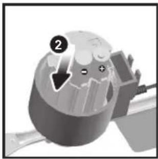
natural_image
Cross-sectional diagram of a mechanical component with internal structure and labeled part (no readable text or symbols)natural_image
Illustration of a cylindrical mechanical component with an upward arrow and number 1, no text or symbols present.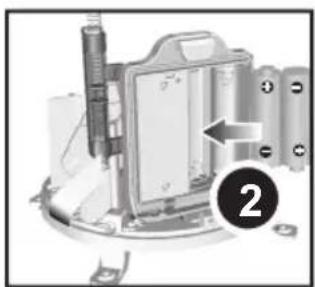
natural_image
Mechanical assembly diagram showing a motor or housing component with a labeled arrow and number 2 (no readable text or symbols)natural_image
Mechanical assembly diagram showing a clamping mechanism with no visible text or symbols- 移除纖維帶。
設定基站
natural_image
Close-up of a device's cable being inserted into a port, showing the cable connector (no text or symbols visible)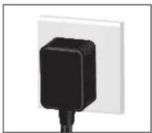
natural_image
Close-up of a black plug attached to a white wall (no text or symbols visible)natural_image
Close-up of a battery rear panel with buttons and a downward arrow indicating a drop (no text or symbols)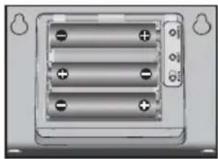
natural_image
Close-up of a battery pack with three batteries and two terminal connectors (no visible text or symbols)natural_image
Mechanical assembly diagram showing a lever mechanism with rotational motion arrows (no text or symbols)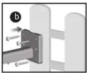
natural_image
Mechanical assembly diagram showing a bracket with bolts and a pin, no text or symbols presentnatural_image
3D rendering of a weathering instrument with propeller and mounting bracket (no text or symbols)natural_image
Diagram showing a device with a plug and outlet, next to a rectangular device (no text or symbols present)檢查連接:
natural_image
Abstract grayscale graphic with a central droplet and cross shape, no text or symbols present.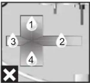
natural_image
Close-up of a mechanical component with a curved arrow indicating motion or force (no visible text or symbols)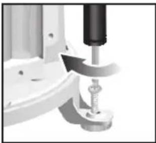
natural_image
Close-up of a mechanical assembly with a spring and lever mechanism (no visible text or symbols)natural_image
Close-up of a device's cable and connector with a USB cable (no text or symbols visible)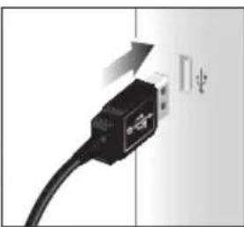
natural_image
Close-up of a black USB cable with a directional arrow indicating compression (no text or symbols visible)操作範圍 -30° C to 60° C (-4° F to 140° F)
準確度 0^ C - 40^ C: +/- 1^ C (+/- 2.0^ F)
40^ C - 50^ C: +/- 2^ C (+/- 4.0^ F)
natural_image
White handheld electronic device with a closed lid and ventilation slots (no visible text or symbols)1×温度/湿度传感器
natural_image
Pure technical line drawing of a mechanical component without any text, numbers, or symbols1 x 挂墙支架
1×座台支架
2 x AAA UM-4
1.5 V 电池
雨量计
natural_image
Exterior view of a cylindrical metal trash bin with four legs (no text or symbols visible)1×雨水收集器
4×螺丝钉
(B类)
natural_image
Mechanical diagram showing a rotating component with three spherical heads and an arrow indicating rotation (no text or symbols)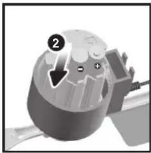
natural_image
Close-up of a mechanical component with a circular head and internal features, no visible text or symbolsnatural_image
Illustration of a cylindrical industrial component with an upward arrow and number 1, no text or symbols present.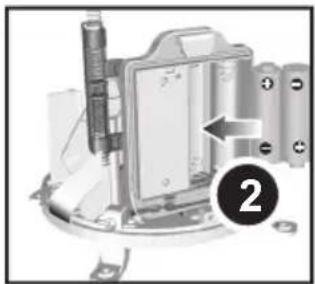
natural_image
Mechanical assembly diagram showing a component with a labeled arrow and numbered marker (no readable text or symbols)natural_image
Mechanical assembly with a numbered label '3' pointing to a component (no readable text or symbols)- 移除纤维带。
设置基站
natural_image
Close-up of a cable being inserted into a device (no text or symbols visible)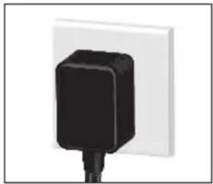
natural_image
Close-up of a black plug inserted into a white wall socket (no text or symbols visible)natural_image
Close-up of a battery pack with two terminals and a downward arrow indicating a drop (no text or symbols)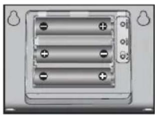
natural_image
Close-up of a battery pack with three leads and two terminals (no visible text or symbols)natural_image
Mechanical assembly diagram showing a metal bracket with rotational motion arrows (no text or symbols)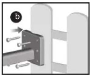
natural_image
Mechanical assembly diagram showing a bracket with bolts and a circular indicator (no text or symbols)natural_image
3D rendered mechanical component with propeller and mounting bracket (no text or symbols)natural_image
Diagram showing a device with a handle and a separate rectangular panel, both without any text or symbols.natural_image
Abstract grayscale graphic with a central droplet and surrounding geometric shapes (no text or symbols)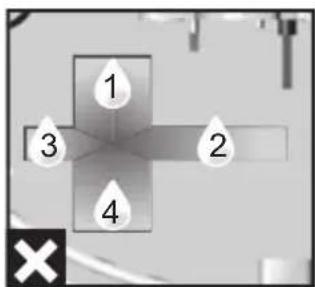
natural_image
Close-up of a mechanical component with a curved arrow indicating motion or force (no text or symbols visible)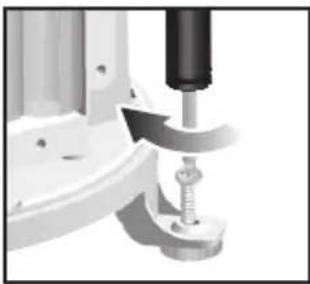
natural_image
Close-up of a mechanical assembly with a tool and spring (no visible text or symbols)natural_image
Close-up of a device's cable and connector with a USB cable (no text or symbols visible)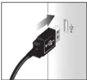
natural_image
Close-up of a USB cable with a directional arrow indicating compression (no text or symbols)操作范围 -30° C to 60° C (-4° F to 140° F)
准确度 0^ C - 40^ C : + / - 1^ C (+/- 2.0°F) 40^ C - 50^ C : + / - 2^ C (+/- 4.0°F)
记忆现时、最低及最高温度。
露水点的最低和最高点
户内相对湿度
| 操作范围 | 25% to 90% |
| 准确度 | 25% - 40%: +/- 7% |
| 40% - 80%: +/- 5% | |
| 80% - 90%: +/- 7% | |
| 记忆 | 现时、最低及最高值 |
无线电控制/原子时钟
同步功能 自动或关闭
时钟显示 小时:分钟:秒数
小时格式 12 小时制 (上午/下午)
或 24 小时制
行事历 日期/月份 或 月份/日期
星期能以6种语言
显示
英文、德文、法文、意大利
文、西班牙文、俄文)
遥控风力感应装置
长×宽×高178×76×214毫米
$$ (7 \times 3 \times 8. 4 \text { 寸 }) $$
Oregon Scientific Inc.
Tualatin, Oregon USA
欧西亚中国授权制造商
展科电子(深圳)有限公司
制造地:中国深圳宝安臣田工业村

- Full Wireless Weather Station Kit
- with USB upload
- Model: WMR89 / WMR89A
- USER MANUAL
- CONTENTS
- INTRODUCTION
- PACKAGING CONTENTS
- BASE STATION
- WIND SENSOR
- TEMPERATURE & HUMIDITY SENSOR
- RAIN GAUGE
- ACCESSORIES - SENSORS
- OVERVIEW
- TOP VIEW
- BACK VIEW
- LCD DISPLAY
- Wind speed/wind direction/wind chill area
- Barometer/UV/Rainfall Area
- Clock/calendar/moon phase area
- OUTDOOR TEMPERATURE / HUMIDITY SENSOR
- GETTING STARTED
- SET UP REMOTE WIND SENSOR
- SET UP REMOTE TEMPERATURE / HUMIDITY SENSOR
- To set up the remote sensor:
- SET UP RAIN GAUGE
- SET UP BASE STATION
- MOUNTING/PLACING OF SENSORS
- To check the connection:
- TEMPERATURE / HUMIDITY SENSOR
- To ensure a level plane:
- BACKLIGHT
- CLOCK RECEPTION
- WMR89:
- WMR89A:
- CLOCK / CALENDAR
- To manually set the clock:
- To change the clock display:
- MOON PHASE
- AUTO SCANNING FUNCTION
- To activate the outdoor temperature and humidity auto-scan function:
- WEATHER FORECAST
- TEMPERATURE AND HUMIDITY
- The weather station displays indoor and outdoor readings for:
- To select the temperature measurement unit:
- To clear the memories and timestamp for the temperature, humidity, heat index and dew point readings:
- TEMPERATURE AND HUMIDITY TREND
- To select the wind speed unit:
- To clear minimum wind chill reading/maximum wind speed reading:
- BAROMETER/UV/RAINFALL
- To view the barometer/UV/rainfall readings:
- To select the measurement unit for the barometer or rainfall readings:
- BAROMETER
- To set the altitude level compensation for the Barometer readings:
- UV INDEX
- To view the maximum UV reading:
- To clear maximum UV reading:
- RAINFALL
- To view the recorded rainfall of the current hour or last 24 hours:
- REVIEW STORED DATA
- To review the data history:
- NOTE
- UPLOAD DATA TO PC SOFTWARE
- RESET
- SPECIFICATIONS
- INDOOR BAROMETER
- INDOOR TEMPERATURE
- PRECAUTIONS
- ABOUT OREGON SCIENTIFIC
- EU-DECLARATION OF CONFORMITY
- COUNTRIES RTTE APPROVAL COMPLIED
- FCC STATEMENT
- DECLARATION OF CONFORMITY
- We
- declare that the product
- DISPOSAL INFORMATION FOR USERS
- IMPOSTARE LA TEMPERATURA REMOTA/SENSORE UMIDITA'
- AUSSENTEMPERATUR / LUFTFEUCHTIGEITS-SENSOR
- PLUVIÓMETRO
- SENSOR EXTERNO DE TEMPERATURA Y HUMEDAD
- IMPORTANTE
- CONSEJO
- NOTA
- PLUVIÔMETRO
- SENSOR DE TEMPERATURA EXTERIOR/UMIDADE
- REGENMETER
- ACCESSOIRES - SENSOREN
- VOORBEREIDING
- REMOTE WINDSENSOR UNIT
- VINDMÄTARE
- TILLBEHÖR - GIVARE
- O UTOMHUS TEMPERATUR/LUFTFUKTIGHETSGIVARE
- KOMMA IGÅNG
- STÄLLA IN BASSTATIONEN
- Kontrollera anslutning:
- 雨量计
- 配件-感應器
- 設定基站
- 设置基站
- 无线电控制/原子时钟
- 遥控风力感应装置
Brand : OREGON SCIENTIFIC
Model : WMR 89
Category : Weather Station