
D16M - Dehumidifier GORENJE - Free user manual and instructions
Find the device manual for free D16M GORENJE in PDF.


| Brand | Gorenje |
| Model | D16M |
| Product Type | Portable Dehumidifier |
| Dehumidification Capacity | 16 L/day (at 30°C, 80% RH) |
| Power Supply | 220-240 V ~ 50 Hz |
| Power Consumption | Approx. 200 W (depending on mode) |
| Refrigerant Type | R290 (flammable) |
| Operating Temperature Range | 5°C to 35°C (41°F to 95°F) |
| Humidity Setting Range | 35% to 85% RH (in 5% increments) |
| Fan Speeds | Normal and High (Turbo) |
| Modes | Dehumidifying, Dryer, Continuous, Smart |
| Timer | Auto start/stop, 0.5 to 24 hours |
| Ionizer | Yes (optional, can be turned on/off) |
| Auto Defrost | Yes |
| Auto Restart | Yes (after power failure) |
| Bucket Capacity | Approx. 4 L |
| Continuous Drain | Yes (via hose, not included) |
| Air Filter | Washable, clean every 30 days |
| Noise Level | Approx. 45 dB (normal fan speed) |
| Dimensions (W x D x H) | Approx. 35 x 25 x 55 cm |
| Weight | Approx. 12 kg |
| Safety Features | Auto shut-off when bucket full, overload protection, grounding plug |
| Warranty | See manufacturer label |
Frequently Asked Questions - D16M GORENJE
User questions about D16M GORENJE
0 question about this device. Answer the ones you know or ask your own.
Ask a new question about this device
Download the instructions for your Dehumidifier in PDF format for free! Find your manual D16M - GORENJE and take your electronic device back in hand. On this page are published all the documents necessary for the use of your device. D16M by GORENJE.
USER MANUAL D16M GORENJE
natural_image
White portable air purifier with 'gorenje' branding on front panel (no other text or symbols visible)D 16/20 M
| RAZVLAŽILNIK – NAVODILA ZA NAMESTITEV IN UPORABO SI | |
| DEHUMIDIFIER – INSTALLATION AND USER MANUAL GB | |
| ОБЕЗВЛАЖНИТЕЛ – РЪКОВОДСТВО ЗА ИНСТАЛИРАНЕ И УПОТРЕБА BG | |
| ODVLHČOVAČ VZDUCHU – NÁVOD NA OBSLUHU A INŠTALÁCI SK | |
| APSORBER VLAGE – UPUTSTVA ZA INSTALACIJU I UPOTREBUSRB/MNE | |
| ODVLAŽIVAČ – UPUTE ZA POSTAVLJANJE I UPORABUCRO/BIH | |
| PÁRAMENTESÍTŐ – ÜZEMBE HELYEZÉSI ÉS HASZNÁLATI UTASÍTÁS HU | |
| DEZUMIDIFICATOR – MANUAL DE INSTALARE ŞI UTILIZARE RO | |
| ОСУШУВАЧ ПОВІТРЯ – ПОСІБНИК З УСТАНОВКИ ТА ЕКСПЛУАТАЦІЇ UA | |
| OSUSZACZ POWIETRZA – INSTRUKCJA MONTAŽU I OBSŁUGI PL | |
| LUFTENTFEUCHTER – MONTAGE- UND BEDIENUNGSANLEITUNGEN DE | |
| Апсорбатор на влага – упатство за инсталација и употРЕБА MK | |
| ОСУШИТЕЛЬ ВОЗДУХА-ИНСТРУКЦИЯ ПО УСТАНОВКЕ И ЭКСПЛУАТАЦИИ RU | |
| ODVLHČOVAČ-NÁVOD K MONTÁŽI A POUŽITÍ CS |
SLO
D 16/20 M
natural_image
Pure electrical circuit lines without any symbolsVarnostna opozorila
Postavitev enote
natural_image
Line drawing of a portable electronic device with lid and buttons (no text or symbols)- Posodo držite na obeh straneh, držite jo vodoravno in jo popolnoma odstranite iz naprave.
natural_image
Diagram of a portable air purifier with a door and vent, showing internal components and airflow direction (no text or labels)- Izpraznite vodo iz posode.
OPOZORILA:
natural_image
Technical line drawing of a portable air conditioner unit with ventilation grille and handle (no text or symbols)Odstranite pokrovček
natural_image
Line drawing of a portable air conditioner unit with ventilation grilles and cooling fins (no text or symbols)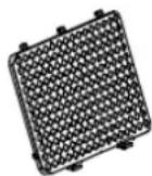
Before operating this product, please read the instructions carefully and keep this manual for future reference.
DEHUMIDIFIER
INSTALLATION AND USER MANUAL
- Please read this manual before installing the product.
- If the power cord is damaged, replacement work shall be performed by authorized personnel only.
- Installation work must be performed in accordance with the national wiring Standards by authorized personnel only.
- Contact an authorized service technician for repair, maintenance or installation of this unit.
When using this dehumidifier in the European countries, the following information must be followed:
DISPOSAL: Do not dispose this product as unsorted municipal waste. Collection of such waste separately for special treatment is necessary.
It is prohibited to dispose of this appliance in domestic household waste.
For disposal, there are several possibilities:
a) The municipality has established collection systems, where electronic waste can be disposed of at least free of charge to the user.
b) When buying a new product, the retailer will take back the old product at least free of charge.
c) The manufacture will take back the old appliance for disposal at least free of charge to the user.
d) As old products contain valuable resources, they can be sold to scrap metal dealers.
Wild disposal of waste in forests and landscapes endangers your health when hazardous substances leak into the ground-water and find their way into the food chain.
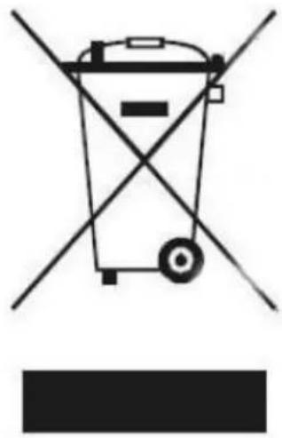
natural_image
Symbolic illustration of a trash bin crossed with diagonal lines, no text or labels presentTo prevent injury to the user or other people and property damage, the following instructions must be followed. Incorrect operation due to ignoring of instructions may cause harm or damage.
The seriousness is classified by the following indications.
| WARNING | This symbol indicates the possibility of death or serious injury. |
| CAUTION | This symbol indicates the possibility of injury or damage to property. |
Meanings of symbols used in this manual are as shown below.
| Never do this! | |
| Always do this! |
WARNING
| Do not exceed the rating of the power socket or connection device. | Do not operate or stop the unit by switching on or off the power. | Do not damage or use an unspecified power cord. | |
| Otherwise, it may cause electric shock or fire due to excess heat generation. | It may cause electric shock or fire due to heat generation. | It may cause electric shock or fire. | |
| Do not modify power cord length or share the outlet with other appliances | Do not operate with wet hands or in damp environment. | Do not direct airflow at room occupants only. | |
| It may cause electric shock or fire due to heat generation. | It may cause electric shock. | This could damage your health. | |
| Before cleaning, turn off the power and unplug the unit | Do not allow water to run into electric parts. | Always install circuit breaker and a dedicated power circuit. | |
| It may cause electric shock or injury. | It may cause failure of machine or electric shock. | No installation may cause fire and electric shock. | |
| Disconnect the power if strange sounds, | Do not drink water drained from the unit. | Do not open the unit during operation. | |
| smell, or smoke comes from it. | |||
| It may cause fire and electric shock. | It is contaminated and could make you sick. | It may cause electric shock. | |
| Do not take the water bucket out during operation | Do not place unit close to heating sources. | Do not use the machine near flammable gas or combustibles, such as gasoline, benzene, thinner, etc. | |
| There is risk of electric shock. | Plastic parts may melt and fire and electric shock. | It may cause an explosion or fire. | |
| Ventilate room before operating dehumidifier if there is a gas leakage from another appliance. | Do not disassemble or modify unit. | ||
| It may cause explosion, fire and, burns. | It may cause failure and electric shock. | ||
CAUTION
| Do not use the unit in small spaces. | Do not put in places where water may splash onto the unit. | Place the unit on a level, sturdy section of the floor. |
| Lack of ventilation can cause overheating and fire. | It may cause an electric shock or fire. | If the unit falls over, it may cause water to spill and damage belongings, or cause electrical shock or fire. |
| Do not cover the intake or exhaust openings with cloths or towels. | Care should be taken when using the unit in a room with the following persons: | Do not use in areas where chemicals are handled. |
| A lack of air flow can lead to overheating and fire. | Infants, children, elderly people, and people not sensitive to humidity. | This will cause the unit deterioration due to chemicals and solvents dissolved in the air. |
| Never insert your finger or other foreign objects into grills or openings. Take special care to warn children of these dangers. | Do not place heavy object on the power cord and take care so that the cord is not compressed. | Do not climb up on or sit on the unit. |
| It may cause electric shock or failure of appliance. | There is danger of fire or electric shock. | You may be injured if you fall or if the unit falls over. |
| Always insert the filters securely. Clean filter every two weeks. | If water enters the unit, turn the unit off and disconnect the power, contact a qualified service technician. | Do not place flower vases or other water container on top of the unit. |
| Operation without filters may cause failure. | It may cause failure of appliance or accident. | Water may spill inside the unit, causing insulation failure and electrical shock or fire. |
- This appliance can be used by children aged from 8 years and above and persons with reduced physical, sensory or mental capabilities or lack of experience and knowledge if they have been given supervision or instruction concerning use of the appliance in a safe way and understand the hazards involved. Children shall not play with the appliance. Cleaning and user maintenance shall not be made by children without supervision. (be applicable for the European Countries).
- This appliance is not intended for use by persons (including children) with reduced physical, sensory or mental capabilities or lack of experience and knowledge, unless they have been given supervision or instruction concerning use of the appliance by a person responsible for their safety. Children should be supervised to ensure that they do not play with the appliance. (be applicable for other countries except the European Countries).
- If the supply cord is damaged, it must be replaced by the manufacturer, its service agent or similarly qualified persons in order to avoid a hazard.
- The appliance shall be installed in accordance with national wiring regulations.
- The appliance with electric heater shall have at least 1 meter space to the combustible materials.
- Contact the authorised service technician for repair or maintenance of this unit.
- Do not use the socket if it is loose or damaged.
- Do not operate your air conditioner in a wet room such as a bathroom or laundry room. Do not use this product for functions other than those described in this instruction manual.
- Contact the authorised installer for installation of this unit.
- If the air conditioner is knocked over during use, turn off the unit and unplug it from the main power supply immediately. Visually inspect the unit to ensure there is no damage. If you suspect the unit has been damaged, contact a technician or customer service for assistance.
- In a thunderstorm, the power must be cut off to avoid damage to the machine due to lightning.
- To reduce the risk of fire or electric shock, do not use this fan with any solid-state speed control device.
- Do not run cord under carpeting. Do not cover cord with throw rugs, runners, or similar coverings. Do not route cord under furniture or appliances. Arrange cord away from traffic area and where it will not be tripped over.
- Do not open the unit during operation.
- When the air filter is to be removed, do not touch the metal parts of the unit
- Hold the plug by the head of the power plug when taking it out.
Electrical Information
- The manufactures nameplate is located on the rear panel of the unit and contains electrical and other technical data specific to this unit.
- Be sure the unit is properly grounded. To minimize shock and fire hazards, proper grounding is important. The power cord is equipped with a three-prong grounding plug for protection against shock hazards.
- Your unit must be used in a properly grounded wall receptacle. If the wall receptacle you intend to use is not adequately grounded or protected by a time delay fuse or circuit breaker (the fuse or circuit breaker needed is determined by the maximum current of the unit. The maximum current is indicated on the nameplate located on unit), have a qualified electrician install the proper receptacle.
- Ensure the receptacle is accessible after the unit installation.
- Do not use extension cords or an adapter plugs with this unit. However, if it is necessary to use an extension cord, use an approved Dehumidifier extension cord only (available at most local hardware stores).
- To avoid the possibility of personal injury, always disconnect the power supply to the unit, before installing and/or servicing.
- All wiring must be performed strictly in accordance with the wiring diagram located on the middle baffle of the unit (behind of the water bucket).
Take note the fuse specifications
The unit s circuit board(PCB) is designed with a fuse to provide overcurrent protection. The specifications of the fuse are printed on the circuit board, such as: T 3.15A/250V (or 350V), etc.
NOTE: All the pictures in the manual are for explanation purposes only. The actual shape of the unit you purchased may be slightly different, but the operations and functions are the same.
Note About Fluorinated Gasses
-Fluorinated greenhouse gases are contained in hermetically sealed equipment. For specific information on the type, the amount and the CO2 equivalent in tonnes of the fluorinated greenhouse gas(on some models), please refer to the relevant label on the unit itself.
-Installation, service, maintenance and repair of this unit must be performed by a certified technician.
-Product uninstallation and recycling must be performed by a certified technician.
WARNINGS (for using R290/R32 refrigerant only)
- Do not use means to accelerate the defrosting process or to clean, other than those recommended by the manufacturer.
- The appliance shall be stored in a room without continuously operating ignition sources (for example: open flames, an operating gas appliance or an operating electric heater).
- Do not piercê or burn.
- Be aware that the refrigerants may not contain an odour.
- Appliance should be installed, operated and stored in a room with a floor area larger than 4 m2.
- Compliance with national gas regulations shall be observed.
- Keep ventilation openings clear of obstruction.
- The appliance shall be stored so as to prevent mechanical damage from occurring.
- A warning that the appliance shall be stored in a well-ventilated area where the room size corresponds to the room area as specified for operation.
- Any person who is involved with working on or breaking into a refrigerant circuit should hold a current valid certificate from an industry-accredited assessment authority, which authorises their competence to handle refrigerants safely in accordance with an industry recognised assessment specification.
- Servicing shall only be performed as recommended by the equipment manufacturer. Maintenance and repair requiring the assistance of other skilled personnel shall be carried out under the supervision of the person competent in the use of flammable refrigerants.
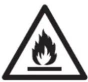
Caution: Risk of fire/ flammable materials (Required for R32/R290 units only)

IMPORTANT NOTE: Read this manual carefully before installing or operating your new air conditioning unit. Make sure to save this manual for future reference.
Explanation of symbols displayed on the unit(For the unit adopts R32/R290 Refrigerant only):
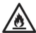
WARNING This symbol shows that this appliance used a flammable refrigerant. If the refrigerant is leaked and exposed to an external ignition source, there is a risk of fire.

CAUTION This symbol shows that the operation manual should be read carefully.

CAUTION This symbol shows that a service personnel should be handling this equipment with reference to the installation manual.

CAUTION This symbol shows that information is available such as the operating manual or installation manual.
- Transport of equipment containing flammable refrigerants.
See transport regulations.
- Marking of equipment using signs.
See local regulations.
3.Disposal of equipment using flammable refrigerants.
See national regulations.
4.Storage of equipment/appliances.
The storage of equipment should be in accordance with the manufacturer's instructions.
5.Storage of packed (unsold) equipment.
Storage package protection should be constructed such that mechanical damage to the equipment inside the package will not cause a leak of the refrigerant charge.
The maximum number of pieces of equipment permitted to be stored together will be determined by local regulations.
6.Information on servicing.
1) Checks to the area.
Prior to beginning work on systems containing flammable refrigerants, safety checks are necessary to ensure that the risk of ignition is minimised. For repair to the refrigerating system, the following precautions shall be complied with prior to conducting work on the system.
2)Work procedure.
Work shall be undertaken under a controlled procedure so as to minimise the risk of a flammable gas or vapour being present while the work is being performed.
3)General work area.
All maintenance staff and others working in the local area shall be instructed on the nature of work being carried out. Work in confined spaces shall be avoided. The area around the workspace shall be sectioned off. Ensure that the conditions within the area have been made safe by control of flammable material.
4) Checking for presence of refrigerant.
The area shall be checked with an appropriate refrigerant detector prior to and during work, to ensure the technician is aware of potentially flammable atmospheres. Ensure that the leak detection equipment being used is suitable for use with flammable refrigerants, i.e. non-sparking, adequately sealed or intrinsically safe.
5)Presence of fire extinguisher.
If any hot work is to be conducted on the refrigeration equipment or any associated parts, appropriate fire extinguishing equipment shall be available to hand. Have a dry powder or CO2 fire extinguisher adjacent to the charging area. 6) No ignition sources.
No person carrying out work in relation to a refrigeration system which involves exposing any pipe work that contains or has contained flammable refrigerant shall use any sources of ignition in such a manner that it may lead to the risk of fire or explosion. All possible ignition sources, including cigarette smoking, should be kept sufficiently far away from the site of installation, repairing, removing and disposal, during which flammable refrigerant can possibly be released to the surrounding space. Prior to work taking place, the area around the equipment is to be surveyed to make sure that there are no flammable hazards or ignition risks. No Smoking signs shall be displayed.
7) Ventilated area.
Ensure that the area is in the open or that it is adequately ventilated before breaking into the system or conducting any hot work. A degree of ventilation shall continue during the period that the work is carried out. The ventilation should safely disperse any released refrigerant and preferably expel it externally into the atmosphere.
8) Checks to the refrigeration equipment.
Where electrical components are being changed, they shall be fit for the purpose and to the correct specification. At all times the manufacturer's maintenance and service guidelines shall be followed. If in doubt consult the manufacturer's technical department for assistance.
The following checks shall be applied to installations using flammable refrigerants:
The charge size is in accordance with the room size within which the refrigerant containing parts are installed;
The ventilation machinery and outlets are operating adequately and are not obstructed;
If an indirect refrigerating circuit is being used, the secondary circuit shall be checked for the presence of refrigerant;
Marking to the equipment continues to be visible and legible. Markings and signs that are illegible shall be corrected;
Refrigeration pipe or components are installed in a position where they are unlikely to be exposed to any substance which may corrode refrigerant containing components, unless the components are constructed of materials which are inherently resistant to being corroded or are suitably protected against being so corroded.
9) Checks to electrical devices.
Repair and maintenance to electrical components shall include initial safety checks and component inspection procedures. If a fault exists that could compromise safety, then no electrical supply shall be connected to the circuit until it is satisfactorily dealt with. If the fault cannot be corrected immediately but it is necessary to continue operation, an adequate temporary solution shall be used. This shall be reported to the owner of the equipment so all parties are advised.
Initial safety checks shall include:
That capacitors are discharged: this shall be done in a safe manner to avoid possibility of sparking;
That there no live electrical components and wiring are exposed while charging, recovering or purging the system;
That there is continuity of earth bonding.
7. Repairs to sealed components.
1) During repairs to sealed components, all electrical supplies shall be disconnected from the equipment being worked upon prior to any removal of sealed covers, etc. If it is absolutely necessary to have an electrical supply to equipment during servicing, then a permanently operating form of leak detection shall be located at the most critical point to warn of a potentially hazardous situation.
2) Particular attention shall be paid to the following to ensure that by working on electrical components, the casing is not altered in such a way that the level of protection is affected. This shall include damage to cables, excessive number of connections, terminals not made to original specification, damage to seals, incorrect fitting of glands, etc.
Ensure that apparatus is mounted securely.
Ensure that seals or sealing materials have not degraded such that they no longer serve the preventing the ingress of flammable atmospheres.
Replacement parts shall be in accordance with the manufacturer's specifications.
NOTE: The use of silicon sealant may inhibit the effectiveness of some types of leak detection equipment. Intrinsically safe components do not have to be isolated prior to working on them.
8. Repair to intrinsically safe components.
Do not apply any permanent inductive or capacitance loads to the circuit without ensuring that this will not exceed the permissible voltage and current permitted for the equipment in use. Intrinsically safe components are the only types that can be worked on while live in the presence of a flammable atmosphere. The test apparatus shall be at the correct rating. Replace components only with parts specified by the manufacturer. Other parts may result in the ignition of refrigerant in the atmosphere from a leak.
9.Cabling.
Check that cabling will not be subject to wear, corrosion, excessive pressure, vibration, sharp edges or any other adverse environmental effects. The check shall also take into account the effects of aging or continual vibration from sources such as compressors or fans.
10. Detection of flammable refrigerants.
Under no circumstances shall potential sources of ignition be used in the searching for or detection of refrigerant leaks. A halide torch (or any other detector using a naked flame) shall not be used.
11.Leak detection methods.
The following leak detection methods are deemed acceptable for systems containing flammable refrigerants. Electronic leak detectors shall be used to detect flammable refrigerants, but the sensitivity may not be adequate, or may need re-calibration. (Detection equipment shall be calibrated in a refrigerant-free area.) Ensure that the detector is not a potential source of ignition and is suitable for the refrigerant used. Leak detection equipment shall be set at a percentage of the LFL of the refrigerant and shall be calibrated to the refrigerant employed and the appropriate percentage of gas (25 % maximum) is confirmed. Leak detection fluids are suitable for use with most refrigerants but the use of detergents containing chlorine shall be avoided as the chlorine may react with the refrigerant and corrode the copper pipe-work. If a leak is suspected, all naked flames shall be removed/ extinguished. If a leakage of refrigerant is found which requires brazing, all of the refrigerant shall be recovered from the system, or isolated (by means of shut off valves) in a part of the system remote from the leak. Oxygen free nitrogen (OFN) shall then be purged through the system both before and during the brazing process.
12. Removal and evacuation.
When breaking into the refrigerant circuit to make repairs or for any other purpose conventional procedures shall be used. However, it is important that best practice is followed since flammability is a consideration. The following procedure shall be adhered to:
Remove refrigerant;
Purge the circuit with inert gas;
Evacuate;
Purge again with inert gas;
Open the circuit by cutting or brazing.
The refrigerant charge shall be recovered into the correct recovery cylinders.
The system shall be flushed with OFN to render the unit safe. This process may need to be repeated several times. Compressed air or oxygen shall not be used for this task.
Flushing shall be achieved by breaking the vacuum in the system with OFN and continuing to fill until the working pressure is achieved, then venting to atmosphere, and finally pulling down to a vacuum. This process shall be repeated until no refrigerant is within the system. When the final OFN charge is used, the system shall be vented down to atmospheric pressure to enable work to take place. This operation is absolutely vital if brazing operations on the pipework are to take place.
Ensure that the outlet for the vacuum pump is not close to any ignition sources and there is ventilation available.
13.Charging procedures.
In addition to conventional charging procedures, the following requirements shall be followed. Ensure that contamination of different refrigerants does not occur when using charging equipment. Hoses or lines shall be as short as possible to minimise the amount of refrigerant contained in them.
Cylinders shall be kept upright.
Ensure that the refrigeration system is earthed prior to charging the system with refrigerant. Label the system when charging is complete (if not already).
Extreme care shall be taken not to overfill the refrigeration system.
Prior to recharging the system it shall be pressure tested with OFN. The system shall be leak tested on completion of charging but prior to commissioning. A follow up leak test shall be carried out prior to leaving the site.
14.Decommissioning.
Before carrying out this procedure, it is essential that the technician is completely familiar with the equipment and all its detail. It is recommended good practice that all refrigerants are recovered safely. Prior to the task being carried out, an oil and refrigerant sample shall be taken in case analysis is required prior
to re-use of reclaimed refrigerant. It is essential that electrical power is available before the task is commenced.
a) Become familiar with the equipment and its operation.
b) Isolate system electrically.
c) Before attempting the procedure ensure that:
Mechanical handling equipment is available, if required, for handling refrigerant cylinders; All personal protective equipment is available and being used correctly;
The recovery process is supervised at all times by a competent person;
Recovery equipment and cylinders conform to the appropriate standards.
d) Pump down refrigerant system, if possible.
e) If a vacuum is not possible, make a manifold so that refrigerant can be removed from various parts of the system.
f) Make sure that cylinder is situated on the scales before recovery takes place.
g) Start the recovery machine and operate in accordance with manufacturer's instructions.
h) Do not overfill cylinders. (No more than 80 % volume liquid charge).
i) Do not exceed the maximum working pressure of the cylinder, even temporarily.
j) When the cylinders have been filled correctly and the process completed, make sure that the cylinders and the equipment are removed from site promptly and all isolation valves on the equipment are closed off.
k) Recovered refrigerant shall not be charged into another refrigeration system unless it has been cleaned and checked.
15. Labelling.
Equipment shall be labelled stating that it has been de-commissioned and emptied of refrigerant. The label shall be dated and signed. Ensure that there are labels on the equipment stating the equipment contains flammable refrigerant.
16.Recovery.
When removing refrigerant from a system, either for servicing or decommissioning, it is recommended good practice that all refrigerants are removed safely.
When transferring refrigerant into cylinders, ensure that only appropriate refrigerant recovery cylinders are employed. Ensure that the correct number of cylinders for holding the total system charge is available. All cylinders to be used are designated for the recovered refrigerant and labelled for that refrigerant (i.e. special cylinders for the recovery of refrigerant). Cylinders shall be complete with pressure relief valve and associated shut-off valves in good working order. Empty recovery cylinders are evacuated and, if possible, cooled before recovery occurs.
The recovery equipment shall be in good working order with a set of instructions concerning the equipment that is at hand and shall be suitable for the recovery of flammable refrigerants. In addition, a set of calibrated weighing scales shall be available and in good working order. Hoses shall be complete with leak-free disconnect couplings and in good condition. Before using the recovery machine, check that it is in satisfactory working order, has been properly maintained and that any associated electrical components are sealed to prevent ignition in the event of a refrigerant release. Consult manufacturer if in doubt.
The recovered refrigerant shall be returned to the refrigerant supplier in the correct recovery cylinder, and the relevant Waste Transfer Note arranged. Do not mix refrigerants in recovery units and especially not in cylinders. If compressors or compressor oils are to be removed, ensure that they have been evacuated to an acceptable level to make certain that flammable refrigerant does not remain within the lubricant. The evacuation process shall be carried out prior to returning the compressor to the suppliers. Only electric heating to the compressor body shall be employed to accelerate this process. When oil is drained from a system, it shall be carried out safely.
NOTE: The control panel of the unit you purchased may be slightly different according to the models.
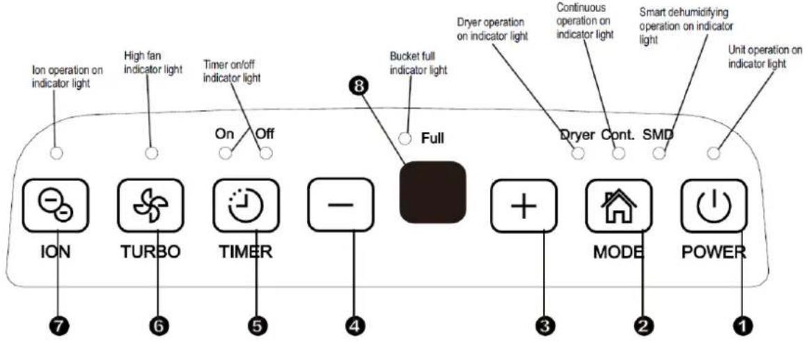
![[High] Low Med Full Dryer Cont. SMD 6 5 4 3 2 1](/content/2026/05/948160/images/0cc4904be10222ac5b4a64c0bf5dfa7417a59ae4b4f9de34a1e5d29e1a540d32.jpg)
Control buttons
When you push the button to change operation modes, the unit will make a beep sound to indicate that it is changing modes.
1. Power button
Press to turn the dehumidifier on and off.
NOTE: When the compressor startups or stops running, the unit may make a loud voice, it is normal.
2. Mode button
Press to select the desired operation mode from Dehumidifying, Dryer, Continuous dehumidifying and Smart dehumidifying.
NOTE: Dryer and Smart dehumidifying modes are optional.
3., 4. Down/Up buttons
The humidity level can be set within a range of 35% RH (Relative Humidity) to 85% RH (Relative Humidity) in 5% increments.
TIMER Set Control buttons
Use the Up/Down buttons to set the Auto start and Auto stop time delay from 0.0 to 24h.
5. Turbo button
Control the fan speed. Press to select either High or Normal fan speed. For maximum moisture removal, set the fan to high speed. When the humidity has been reduced and quiet operation is preferred, set the fan control to Normal.
6. Timer button
Press to select the Auto start and Auto stop feature.
7. Ion button (optional)
Press to activate the Ionizer. Anions are automatically generated by Ionizer. The anions deactivate the chemical vapors and dust. Press it again to deactivate the function.
8. Display
Shows the set % humidity level from 35% to 85%, auto start/stop time (0\~24) while setting and the actual (± 5% accuracy) room % humidity level in a range of 30% RH (Relative Humidity) to 90%RH (Relative Humidity).
Error and Protection Codes:
AS – Humidity sensor error: Unplug the unit and plug it back in. If error repeats, call for service.
ES – Temperature sensor error: Unplug the unit and plug it back in. If error repeats, call for service.
P1 – Unit is in defrost mode: Leave the unit to finish automatically defrost cycle. The protection will clear after the unit self-defrosts.
P2 – Bucket is full or bucket is not in right position: Empty the bucket and replace it in the right position.
E3 – Unit malfunction: Unplug the unit and plug it back in. If error repeats, call for service.
EC – Refrigerant leakage detection: With this new technology, the display area will appear EC when the unit detects refrigerant leakage, call for service.
Other features
Bucket Full
Illuminates when the bucket is ready to be emptied, or when the bucket is removed or not placed in the proper position.
Auto Shut Off
The dehumidifier shuts off when the bucket is full, or when the bucket is removed or not placed in the proper position. When the setting humidity is reached, the unit will be shut off automatically. For some models, the fan motor will continue operating.
Auto Defrost
When frost builds up on the evaporator coils, the compressor will turn off and the fan will continue to run until the frost disappears.
NOTE: In Auto defrosting operation, the unit may make some voice of refrigerant flowing, it is normal.
3 minutes start-up delay
After the unit has stopped, it cannot be restart operation in the first 3 minutes. This is to protect the unit. Operation will automatically start after 3 minutes.
Smart dehumidifying mode (optional)
At smart dehumidifying mode, the unit will automatically control room humidity in a comfortable range 45%\~55% according to the room temperature. The humidity setting function will be invalid.
Auto-Restart
If the unit breaks off unexpectedly due to the power cut, it will restart with the previous function setting automatically when the power resumes.
Setting the Timer
- When the unit is on, first press the Timer button, the Timer Off indicator light illuminates. It indicates the Auto Stop program is initiated. Press it again the Time On indicator light illuminates. It indicates the Auto Start is initiated.
- When the unit is off, first press the Timer button, the TIMER ON indicator light illuminates. It indicates the Auto Start program is initiated. Press it again the Time Off indicator light illuminates. It indicates the Auto Stop is initiated.
- Press or hold the UP or DOWN button to change the Auto time by 0.5 hour increments, up to 10 hours, then at 1 hour increments up to 24 hours. The control will count down the time remaining until start.
- The selected time will register in 5 seconds and the system will automatically revert back to display the previous humidity setting.
- When the Auto start & Auto stop times are set, within the same program sequence, TIMER ON OFF indicator lights illuminate identifying both ON and OFF times are now programmed.
- Turning the unit ON or OFF at any time or adjusting the timer setting to 0.0 will cancel the Auto Start/Stop function.
- When LED display window displays the code of P2, the Auto Start/Stop function will also be cancelled.
Dryer mode (optional)
The unit can make the MAX dehumidification function when it is under the Dryer mode. The fan speed is fixed at high fan speed. The humidity level is automatically controlled according to the actual room humidity. The unit will quit dryer mode after a maximum 10 hours' operation.
NOTE:
- The Dryer mode must be operated in a closed room, do not open the door and window.
- To make the most effective dehumidification, please first dehydrate the wet clothes.
- Make sure to direct airflow at the wet clothes (See Fig.A).
- For thick and heavy wet clothes may not get the best effective dehumidification.

CAUTION
- Do not cover the air outlet of the unit with clothes. It may cause excessive heat, fire or failure of unit.
- Do not place the wet clothes on the top of the unit and do not make the water drop into the unit. It may cause electric shock or failure of unit.
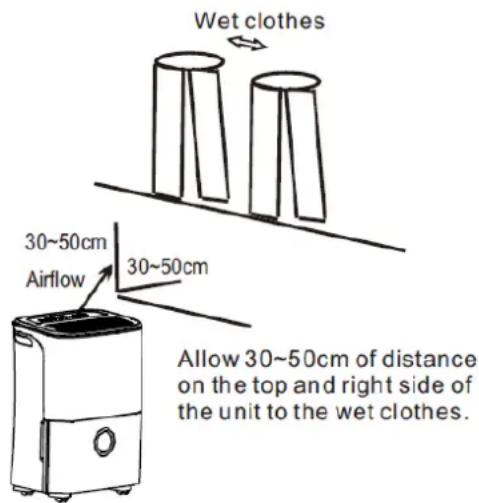
Fig.A
Front
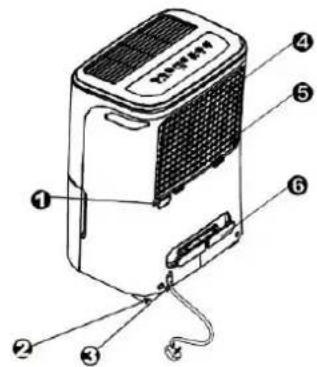
- Control panel
- Handle (both sides)
- Air outlet grille
- Water bucket
- Water level window
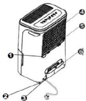
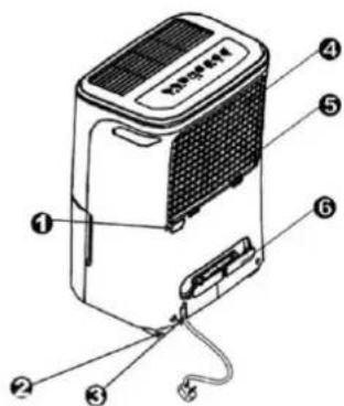
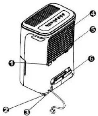
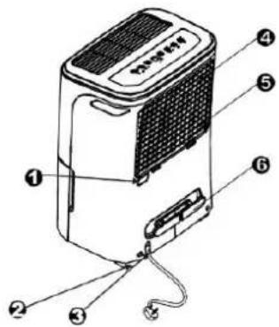
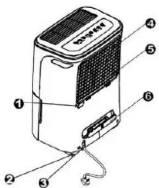
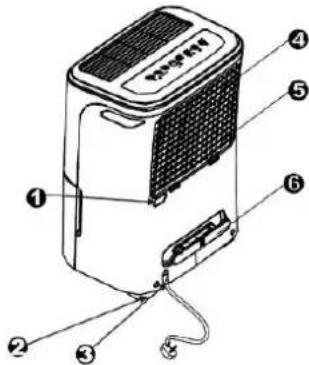
Rear
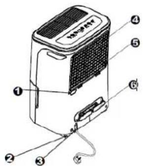
- Drain hose
- Casters
- Power cord with plug
- Air intake grille
- Air filter (behind the grill)
- Power cord holder (used only during the unit is stored)
NOTE: All the pictures in the manual are for explanation purposes only. The actual shape of the unit you purchased may be slightly different, but the operations and functions are the same.
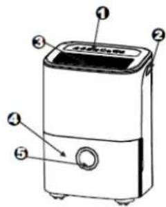
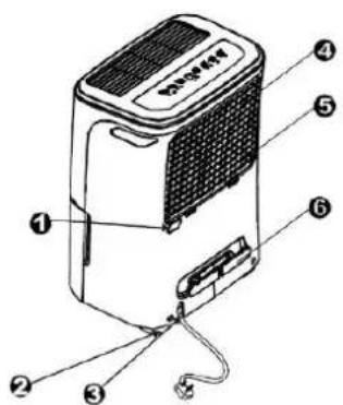
Positioning the unit
A dehumidifier operating in a basement will have little or no effect in drying a storage area, such as a closet, unless there is adequate circulation of air in and out of the area.
- Do not use outdoors.
- This dehumidifier is intended for indoor residential applications only. This dehumidifier should not be used for commercial or industrial applications.
- Place the dehumidifier on a smooth, level floor strong enough to support the unit with a full bucket of water.
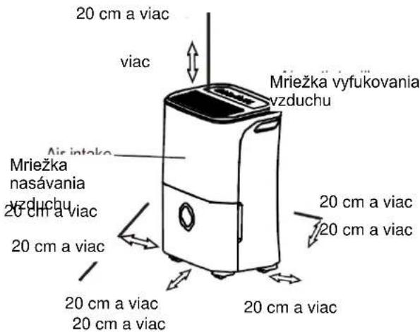
- Allow at least 20cm of air space on all sides of the unit for good air circulation.
- Place the unit in an area where the temperature will not fall below ^5 C (41 F). The coils can become covered with frost at temperatures below 5 ^ C (41 F), which may reduce performance.
- Place the unit away from the clothes dryer, heater or radiator.
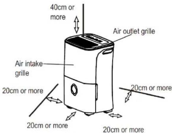
Casters (At four points on the bottom of unit)
- Casters can move freely.
-
Do not force casters to move over carpet, nor move the unit with water in the bucket. (The unit may tip over and spill water.)
-
Use the unit to prevent moisture damage anywhere books or valuables are stored.
- Use the dehumidifier in a basement to help prevent moisture damage.
- The dehumidifier must be operated in an enclosed area to be most effective.
- Close all doors, windows and other outside openings to the room.
Using the unit
- When first using the dehumidifier, operate the unit continuously 24 hours.
- This unit is designed to operate with a working environment between 5°C/41°F and 35°C/95°F.
- If the unit has been switched off and needs to be switched on again quickly, allow approximately three minutes for the correct operation to resume.
- Do not connect the dehumidifier to a multiple socket outlet, which is also being used for other electrical appliances.
- Select a suitable location, and make sure you have easy access to an electrical socket.
- Plug the unit into an electrical socket-outlet with earth connection.
- Make sure the Water bucket is correctly fitted otherwise the unit will not operate properly.
NOTE: When the water in the bucket reaches to a certain level, please be careful to avoid spilling of water.
Removing the collected water
There are two ways to remove collected water.
1. Use the bucket
- When the unit is off, if the bucket is full, the unit will beep 8 times and the Full indicator light will flash and digital display will show P2.
- When the unit is on, if the bucket is full, the compressor turns off and the fan turns off after 30 seconds for drying the water on the condenser, then the unit will beep 8 times and the Full indicator light will flash, the digital display will show P2.
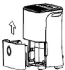
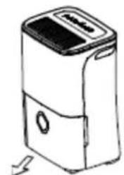
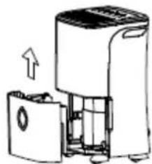
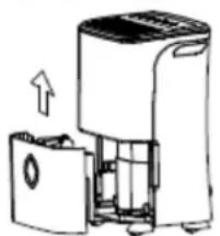
- Slowly pull out the bucket. Grip the left and right handles securely, and carefully pull out straight so water does not spill. Do not put the tank on the floor because the bottom of the bucket is uneven. Otherwise the bucket will fall and cause the water to spill.
- Throw away the water and replace the bucket. The bucket must be in place and securely seated then the dehumidifier can operate.
-
The machine will re-start when the bucket is restored in its correct position.
-
Pull out the bucket a little.
natural_image
Line drawing of a portable electronic device with a lid and ventilation slots (no text or symbols)- Hold both sides of the bucket with even strength, and pull it out from the unit.
natural_image
Diagram of a device with an upward arrow indicating motion or operation (no text or symbols present)- Pour the water out.
NOTES:
- When you remove the bucket, do not touch any parts inside of the unit. Doing so, may damage the product.
- Be sure to push the bucket gently all the way into the unit. Banging the bucket against anything or failing to push it in securely may cause the unit not to operate.
- When you remove the bucket, if there is some water in the unit you must dry it.
2. Continuous draining
- Water can be automatically emptied into a floor drain by attaching the unit with a water hose (not included).
- Cut the cover down from the back drain hose outlet. Attach a drain hose (ID=13.5mm) and lead it to the floor drain or a suitable drainage facility.
- Make sure the hose is secure so there are no leaks.
- Direct the hose toward the drain and make sure that there are no kinks which would stop the water drain.
- Place the end of the hose into the drain and make sure the end of the hose is level or down to let the water flow smoothly. Do never let it up.
- Select the desired humidity setting and fan speed on the unit for continuous draining to start.
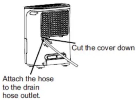
NOTE: When the continuous drain feature is not being used, remove the drain hose from the outlet and close the water outlet.
Care and cleaning the dehumidifier
⚠️ Turn the dehumidifier off and remove the plug from the socket before cleaning.
1. Clean the Grille and Housing
- Use water and a mild detergent. Do not use bleach or abrasive detergents.
- Do not splash water directly onto the unit. Doing so may cause an electrical shock, damage insulation, or cause the unit to rust.
- The air intake and outlet grilles get soiled easily, so use a vacuum cleaner or brush to clean.
2. Clean the bucket
Every few weeks, clean the bucket to prevent growth of mold and bacteria. Partially fill the bucket with clean water and add a little mild detergent and clean, empty and wash out the bucket.
NOTE: Do not use a dishwasher to clean the bucket. After clean, the bucket must be in place and securely seated for the dehumidifier to operate.
3. Clean the air filter
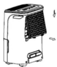
The air filter behind the front grille should be checked and cleaned at least every 30 days or more often if necessary.
NOTE: DO NOT RINSE OR PUT THE FILTER IN AN AUTOMATIC DISHWASHER.
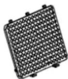
To remove:
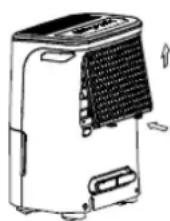
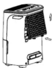
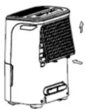
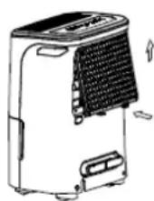
Grip the tab on the filter and pull it upward, then pull it out as shown in Fig. Clean the filter with warm, soapy water. Rinse and let the filter dry before replacing it. Do not clean the filter in a dishwasher.
To attach:
Insert the air filter into the unit from underside to upside. See Fig.
CAUTION:
DO NOT operate the dehumidifier without a filter because dirt and fibers will clog it and reduce performance.
natural_image
Line drawing of a portable air conditioner unit with ventilation grilles and cooling fins (no text or symbols)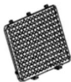
4. When not using the unit for long time periods
• After turning off the unit, wait one day before emptying the bucket.
- Clean the main unit, water bucket and air filter.
- Cover the unit with a plastic bag.
- Store the unit upright in a dry, well-ventilated place.
Before calling for service, review the chart below by yourself.
| Problem | What to do |
| Unit does not start | Make sure the dehumidifiers plug is pushed completely into the socked.Check the fuse/circuit breaker box.Dehumidifier has reached its pre-set level or bucket is full.Water bucket is not in the proper position. |
| Dehumidifier does not dry the air as it should | Leave the unit to operate more time, to remove the moisture.Make sure there are no curtains, blinds or furniture blocking the front or back of the dehumidifier.The humidity control may not be set low enough.Check that all doors, windows and other openings are securely closed.Room temperature is too low, below 5°C (41°F).There is a big source of moisture in the room |
| The unit makes a loud noise when operating | The air filter is clogged.The unit is tilted instead of upright as it should be.The floor surface is not level. |
| Frost appears on the coils | This is normal. The dehumidifier has Auto defrost feature. |
| Water on floor | Hose or hose connection may be loose.Intend to use the bucket to collect water, but the back drain plug is removed. |
| ES, AS, P1 or P2 appear on the display | These are error codes and protection codes. See the CONTROL PADS ON THE DEHUMIDIFIER section. |
BG
D 16/20 M
natural_image
Simple line drawing of a trash bin with two crossed lines indicating no waste or prohibition (no text or symbols)
Fig.A
Отпред
- Hold both sides of the bucket with even strength, and pull it out from the unit.
natural_image
Diagram of a portable air purifier with an open lid and internal compartments (no text or symbols)Fig.6
3. Pour the water out.
natural_image
Line drawing of a portable air conditioner unit with ventilation grilles and cooling fins (no text or symbols)Fig. 8
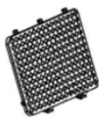
Fig. 9
natural_image
Symbolic illustration of a trash bin crossed with diagonal lines, no text or labels present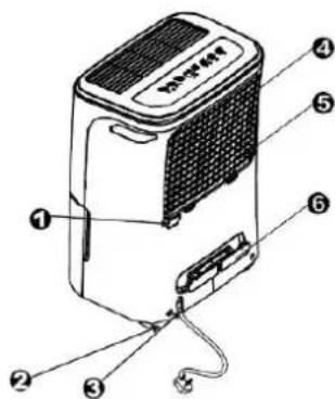
natural_image
Line drawing of a portable electronic device with a lid and ventilation slots (no text or symbols)Fig.5
natural_image
Diagram of a device with an open lid and internal compartments, showing no text or symbols.Obr. 6
- Vylejte vodu von.
POZNÁMKY:
natural_image
Technical line drawing of a portable air conditioner unit with a grid-patterned base (no text or symbols)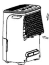
natural_image
Symbolic illustration of a trash bin crossed with diagonal lines, no text or labels present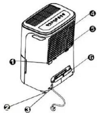
Postavljanje aparata
Rad apsorbera vlage u podrumskim prostorijama imaće lošiji efekat sušenja, odnosno apsorbovanja vlage iz prostora za držanje odeće kao što su npr. šifonjeri, izuzev ukoliko je obezbeđeno odgovarajuće
provetravanje takvih prostorija.
natural_image
Diagram of a device with an open lid and internal compartments, showing no text or symbols.natural_image
Diagram of a portable air conditioner unit with a grid-patterned panel and attached sensors (no text or symbols)Skinite poklopac
Fiksirajte crevo za odvod kondenzata
UPOZORENJE: kada ne želite konstantno odvajanje kondenzata, skinite crevo za odvod kondenzata i zapušite otvor za odvod kondenzata.
Održavanje i čišćenje apsorbera vlage
Pre čišćenja isključite apsorber vlage i izvucite priključni kabl iz električne utičnice.
1. Čišćenje mreže i kućišta
- Koristite blagu mešavinu vode i deterdženta. Nemojte koristiti belilo niti agresivna sredstva za čišćenje.
- Ne polivajte vodu po napravi. Ovo može da uzrokuje električni udar, a može i oštetiti napravu ili prouzročiti rđanje naprave.
- Rešetke, odnosno mreže na ulazu i izlazu vazduha veoma se brzo zaprljaju. Za čišćenje tih delova koristite usisivač.
2. Čišćenje posude kondenzata
natural_image
Simple line drawing of a trash bin with crossed lines indicating no waste or discharge (no text or symbols)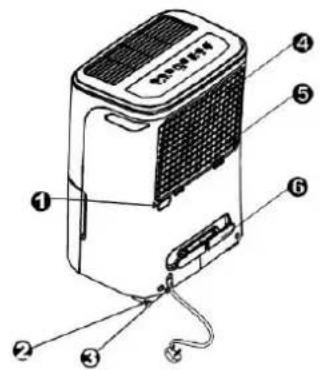
Postavljanje aparata
Rad apsorbera vlage u podrumskim prostorijama imaće lošiji efekat sušenja, odnosno apsorbovanja vlage iz prostora za držanje odeće kao što su npr. šifonjeri, izuzev ukoliko je obezbeđeno odgovarajuće provetravanje takvih prostorija. 40 cm ili više
natural_image
Diagram of a portable air conditioner unit with an open lid and upward arrow indicating motion (no text or symbols)natural_image
Technical line drawing of a portable air conditioner unit with no visible text or symbolsSkinite poklopac
Fiksirajte crevo za odvod kondenzata
Održavanje i čišćenje apsorbera vlage
⚠ Pre čišćenja isključite apsorber vlage i izvucite priključni kabl iz električne utičnice.
1. Čišćenje mreže i kućišta
- Koristite blagu mešavinu vode i deterdženta. Nemojte koristiti belilo niti agresivna sredstva za čišćenje.
- Ne polivajte vodu po napravi. Ovo može da uzrokuje električni udar, a može i oštetiti napravu ili prouzročiti rđanje naprave.
- Rešetke, odnosno mreže na ulazu i izlazu vazduha veoma se brzo zaprljaju. Za čišćenje tih delova koristite usisivač.
2. Čišćenje posude kondenzata
natural_image
Symbol of a trash bin crossed with diagonal lines, representing waste or discharge (no text or labels)
natural_image
Line drawing of a portable electronic device with front panel and side door (no text or symbols)natural_image
Diagram of a portable air conditioner unit with an upward arrow indicating airflow or movement (no text or symbols present)natural_image
Technical line drawing of a portable air conditioner unit with a grid-patterned grille and support bracket (no text or symbols)natural_image
Line drawing of a portable air conditioner unit with ventilation slots and cooling fins (no text or symbols)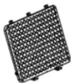
natural_image
Symbolic illustration of a trash bin crossed with diagonal lines, no text or labels present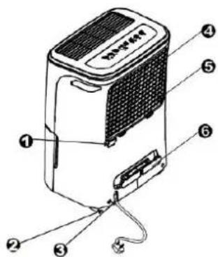
Aşezarea unității
natural_image
Diagram of a portable air purifier with an open lid and internal compartments, showing airflow direction (no text or symbols)- Turnați apa din ea.
NOTE:
natural_image
Line drawing of a portable air conditioner unit with ventilation grilles and cooling fins (no text or symbols)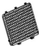
natural_image
Simple line drawing of a trash bin with crossed lines indicating no waste or restriction (no text or symbols)
natural_image
Diagram of a portable air purifier with an upward arrow indicating motion (no text or symbols present)- Вилийте воду.
ПРИМІТКИ.
natural_image
Technical line drawing of a portable air conditioner unit with cooling fins and a handle (no text or symbols)natural_image
Line drawing of a portable air conditioner unit with ventilation slots and cooling fins (no text or symbols)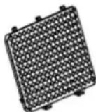
natural_image
Symbol of a trash bin crossed with diagonal lines, representing waste sorting or restriction (no text or labels)
natural_image
Line drawing of a portable electronic device with lid and buttons (no text or symbols)Rys. 5
natural_image
Diagram of a refrigerator with an open door and internal compartments, showing airflow direction (no text or symbols)Rys. 6
- Wylać wodę.
UWAGI:
natural_image
Line drawing of a portable air conditioner unit with ventilation grilles and cooling fins (no text or symbols)Rys. 8
Rys. 9
Zakładanie:
natural_image
Symbolic illustration of a trash bin crossed with diagonal lines, no text or labels presentSicherheitshinweise
natural_image
Line drawing of a portable electronic device with a lid and ventilation slots (no text or symbols)natural_image
Diagram of a portable air purifier with an open lid and internal compartments, showing airflow direction (no text or symbols)natural_image
Technical line drawing of a portable air conditioner unit with a handle and ventilation grille (no text or symbols)Entfernen Deckel.
Sie den
natural_image
Technical illustration of a device with two views: top shows internal grid structure, bottom shows patterned grid (no text or symbols)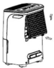
natural_image
Symbol of a trash bin crossed with diagonal lines, representing waste sorting or anti-poverty (no text or labels)
natural_image
Line drawing of a portable electronic device with a lid and ventilation slots (no text or symbols)natural_image
Diagram of a device with an open lid and internal compartments, showing a directional arrow (no text or symbols)natural_image
Line drawing of a portable air conditioner unit with a grid-patterned grille and mounted sensors (no text or symbols)natural_image
Technical line drawings of two household appliances, labeled Fig. 8 and Fig. 9, showing internal components without any text or symbols.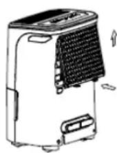
ВНИМАНИЕ:
natural_image
Symbol of a trash bin crossed with diagonal lines, representing waste sorting or anti-poverty (no text or labels)
Размещение прибора
natural_image
Line drawing of a portable electronic device with a lid and ventilation slots (no text or symbols)natural_image
Diagram of a device with an open lid and internal components, showing no text or symbols.natural_image
Diagram of a portable air purifier with mesh grille and mounting bracket (no text or symbols)natural_image
Technical line drawings of a device labeled Fig. 8 and Fig. 9, showing internal components without any text or symbols.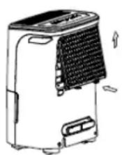
natural_image
Pure electrical circuit lines without any symbols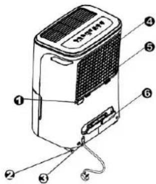
Postavení jednotky
natural_image
Diagram of a portable air purifier with an upward arrow indicating airflow or movement (no text or symbols present)natural_image
Diagram of a portable air conditioner unit with a grid-patterned panel and attached lever (no text or symbols)natural_image
Technical line drawing of a device with two views: top shows internal grid structure, bottom shows patterned grid (no text or symbols)Umístění
- Varnostna opozorila
- Postavitev enote
- OPOZORILA:
- DEHUMIDIFIER
- INSTALLATION AND USER MANUAL
- When using this dehumidifier in the European countries, the following information must be followed:
- Electrical Information
- Take note the fuse specifications
- Note About Fluorinated Gasses
- WARNINGS (for using R290/R32 refrigerant only)
- 6.Information on servicing.
- Repairs to sealed components.
- Repair to intrinsically safe components.
- 9.Cabling.
- Detection of flammable refrigerants.
- 11.Leak detection methods.
- Removal and evacuation.
- 13.Charging procedures.
- 14.Decommissioning.
- Labelling.
- 16.Recovery.
- Control buttons
- Power button
- Mode button
- 3., 4. Down/Up buttons
- TIMER Set Control buttons
- Turbo button
- Timer button
- Ion button (optional)
- Display
- Error and Protection Codes:
- Other features
- Bucket Full
- Auto Shut Off
- Auto Defrost
- minutes start-up delay
- Smart dehumidifying mode (optional)
- Auto-Restart
- Setting the Timer
- Dryer mode (optional)
- NOTE:
- CAUTION
- Front
- Rear
- Positioning the unit
- Casters (At four points on the bottom of unit)
- Using the unit
- Removing the collected water
- Use the bucket
- NOTES:
- Continuous draining
- Care and cleaning the dehumidifier
- ⚠️ Turn the dehumidifier off and remove the plug from the socket before cleaning.
- Clean the Grille and Housing
- Clean the bucket
- Clean the air filter
- To remove:
- To attach:
- CAUTION:
- When not using the unit for long time periods
- Отпред
- POZNÁMKY:
- Postavljanje aparata
- Održavanje i čišćenje apsorbera vlage
- Čišćenje mreže i kućišta
- Čišćenje posude kondenzata
- Aşezarea unității
- ПРИМІТКИ.
- UWAGI:
- Sicherheitshinweise
- Размещение прибора
- Postavení jednotky
- Umístění
Brand : GORENJE
Model : D16M
Category : Dehumidifier