
DHWA 5000-5 INV - Pump T.I.P. - Free user manual and instructions
Find the device manual for free DHWA 5000-5 INV T.I.P. in PDF.


| Product type | Submersible lift pump |
| Model | DHWA 5000-5 INV |
| Brand | T.I.P. |
| Use | Clear water and dirty water (particles up to 5 mm) |
| Motor power | 1500 W |
| Supply voltage | 230 V / 50 Hz |
| Maximum flow rate | 5000 L/h |
| Maximum discharge head | 8 m |
| Dimensions (L × W × H) | 55 × 25 × 25 cm |
| Weight | 18 kg |
| Power cable length | 10 m |
| Protection rating | IP68 |
| Main function | Water pumping and lifting |
| Thermal protection | Yes, with automatic shutdown in case of overheating |
| Dry running | Protected by safety float |
| Maintenance and cleaning | Regularly clean the strainer and pump body |
| Spare parts available | O-ring, impeller, capacitor |
| Repairability | Repairability index: 8/10 |
| Warranty | 2 years |
Frequently Asked Questions - DHWA 5000-5 INV T.I.P.
User questions about DHWA 5000-5 INV T.I.P.
0 question about this device. Answer the ones you know or ask your own.
Ask a new question about this device
Download the instructions for your Pump in PDF format for free! Find your manual DHWA 5000-5 INV - T.I.P. and take your electronic device back in hand. On this page are published all the documents necessary for the use of your device. DHWA 5000-5 INV by T.I.P..
USER MANUAL DHWA 5000-5 INV T.I.P.
natural_image
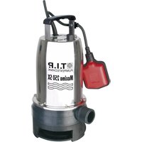
Exterior view of a black and red industrial pump unit (no visible text or symbols on the device body)
Translation of original operating instructions
Automatic domestic water supply

GB EC declaration of conformity We, T.I.P. Technische Industrie Produkte GmbH, Siemensstr. 17, D-74915 Waibstadt, declare in our sole responsibility that the products identified below comply with the basic requirements imposed by the EU directives specified below including all subsequent amendments: 2006/42/EC, 2014/30/EU, 2000/14/EU, 2011/65/EU
Conformity assessment was made according annex V of directive 2000/14/EC
DHWA 5000-5 INERTER: ISO 3744:2010:L WA : measured 54,2 dB ±1,5 dB/guaranteed.: 67 dB Conformity assessment was made according annex V of directive 2000/14/EC
Congratulations for buying your new device from T.I.P.!
We hope you will enjoy your product!
Table of contents
- General safety information.... 1
- Technical Data 2
- Range of use....2
- Scope of delivery 3
- Assembly 3
- Installation.... 3
- Electrical connection 4
- Putting into operation 5
- Function of the pump control / control panel 6
- Maintenance and troubleshooting....7
- Warranty 8
- How to order spare parts....9
- Service 9
Annex: Illustrations
1. General safety information
Please read through these operating instructions carefully and make yourself conversant with the control elements and the proper use of this product. We shall not be liable in the case of damage caused as a result of the non-observance of instructions and provisions of the present operating instructions. Any damage caused as a result of the non-observance of the instructions and regulations contained in the present operating instructions shall not be covered by the warranty terms. Please keep these operating instructions in a safe place and hand them on together with the device should you ever dispose of it.
With the contents of this manual unfamiliar people should not use this device.
The pump must not be used by children.
The pump may be used by persons with reduced physical, sensory or mental capabilities or lack of experience and / or knowledge if they have been supervised or instructed in the safe use of the equipment and have understood the resulting hazards. Children are not allowed to play with the device. Keep the appliance and its cord out of reach of children.
The pump must not be used when people are in the water.
The pump must be supplied through a residual current device (RCD) having a rated residual operating current not exceeding 30mA.
If the supply cord is damaged, it must be replaced by the manufacturer, its service agent or similarly qualified persons in order to avoid a hazard.
Disconnect the device from the power supply and let it cool down before cleaning and maintenance is performed and before the device is stored.
Always protect electrical parts against moisture. During cleaning or operation, they must not be immersed in water or other liquids to ensure that an electrical shock is prevented. Never hold the device under running water. Please follow the instructions of “Maintenance and troubleshooting”.
Notes and instructions with the following symbols require particular attention:

Any nonobservance of these instructions involves the danger of bodily harm to people and/or damage to property.
Any nonobservance of this instruction bears the risk of an electrical shock which may cause damage to persons or property.
Please inspect the device for damage occurred during transportation. In case of damage, the retailer has to be informed immediately, at the latest within 8 days after the date of purchase.
- Technical data
| Model | DHWA 5000-5 INVERTER |
| Mains voltage / frequency | 230 V~ / 50 Hz |
| Nominal performance | Max. 550 Watt |
| Protection type | IPX5 |
| Suction port | female 30.29 mm (1") |
| Pressure port | female 30.29 mm (1") |
| Max. flow rate (Qmax) | 5,000 l/h |
| Max. pressure | 4.8 bar |
| Max. delivery height (Hmax) | 48 m |
| Max. suction height | 5 m |
| Min. ambient temperature | 5 °C |
| Max. ambient temperature | 40 °C |
| Min. fluid temperature | 3 °C |
| Max. fluid temperature | 75 °C |
| Length of connection cable | 1,0 m |
| Cable type | H07RN-F |
| Weight (net) | 8.3 kg |
| Guaranteed sound power level (LWA) | 67 dB |
| Measured sound power level (LPA) | 51,64 dB |
| Dimensions (L x D x H) | 39 x 19.5 x 29.5 cm |
| Item No. | 31113 |
The values were determined with free, unreduced in- an outlet.
Noise emission values obtained according to the EN 12639 regulation. Measurement method according to EN ISO 3744.
3. Range of use
Automatic domestic water pumps with inverter technology from T.I.P. are portable, electric pumps for automatic operation. These high-quality products with their impressive performance data have been developed for a wide range of irrigation, water pumping, domestic water supply and pressurized water distribution purposes.
The devices are suitable for pumping clean, clear water or moderately contaminated water containing solids up to the maximum size specified in the technical data.
Typical applications for automatic domestic water pumps include domestic water supply with service water from wells and cisterns; automatic irrigation of gardens and flower beds as well as sprinkling; filling or emptying of storage tanks, basins and ponds.
The device is not suitable for use in swimming pools.
This product is intended for private domestic use and not for commercial or industrial purposes or for continuous circulation.

The pump is not suited to discharge saltwater, feces, inflammable, corrosive, explosive or other hazardous liquids. Please observe the max. and min. temperatures of the liquids to be discharged stated in the technical data.
4. Scope of delivery
The scope of delivery of this product includes:
A pump with connection cable, instructions for use.
Check that the scope of delivery is complete. Depending on the intended use, additional accessories may be required (see chapter "Installation" and "Ordering spare parts").
If possible, keep the packaging until the warranty period expires. Dispose of packaging materials in an environmentally friendly manner.
5. Assembly
Please also refer to the illustration, which can be found as an appendix at the end of these instructions for use.
- Prepare the threaded connection (not supplied) by wrapping it with Teflon tape to ensure a tight connection.
- Screw the prepared threaded connection firmly onto the suction side of the pump.
- Connect the suction hose to the assembled suction connection and tighten the connection.
- Remove the filler screw (Torx 30) and fill the pump housing with water to prepare the pump.
- Also wrap the threaded connection for the pressure side with Teflon tape and screw on the connection.
- Attach a quick coupling piece to the connection on the pressure side.
- Connect the hose to the pump using the quick-release coupling.
- Plug the pump into the socket and press the on/off switch on the control panel.
You can then set the desired pressure. We recommend a working pressure of 3.0 bar.
6. Installation
6.1. General installation information

During the entire process of installation, the device must not be connected to the electrical mains.

The pump should be installed in a dry place with an ambient temperature not to exceed 40\ °C and not to fall below 3\ °C . The pump and the entire connection system have to be protected from frost and other climatic influences.

When installing the device, please make sure that the motor is sufficiently ventilated.
All connection lines have to be perfectly tight since leaking lines may affect the performance of the pump and cause considerable damage. Therefore, please use Teflon tape to seal the contact surfaces between the threaded sections of the lines and the connection with the pump. This use of sealing material such as Teflon tape is the only way to ensure an airtight assembly. Frequent switching on and off of the pump caused by small leakages and high cut-in pressure must be avoided. See also max starting frequency per hour in the technical data table. Avoid when tightening screw excessive force that may cause damage. When laying the connection pipes, you should make sure that the pump is not exposed to any form of weight, vibration or tension. Moreover, the connection lines must not contain any kinks or an adverse slope. Please observe the illustrations, too, which are contained as an attachment at the end of the present operating instructions.
Use a suction line with the same diameter as the pump's suction connection. However, if the suction height is more than 4 m, we recommend using a 25 % larger diameter - with corresponding constriction pieces at the connections.
The inlet of the suction line must have a suction filter. The filter keeps out larger dirt particles in the water that could clog or damage the pump or the pipe system. The non-return valve prevents the pressure from escaping after the pump has been switched off. It also makes it easier to bleed the suction line by filling it with water. The suction filter - i.e. the inlet of the suction line - must be at least 0.3 m below the surface of the liquid to be pumped. This prevents air from being sucked in. In addition, ensure that the suction line is at a sufficient distance from the bottom and banks of streams, rivers, ponds, etc. to prevent stones, plants, etc. from being sucked in.
6.3. Installation of the pressure line
The pressure line transports the liquid to be pumped from the pump to the tapping point. To avoid flow losses, we recommend using a pressure line that has at least the same diameter as the pressure connection of the pump. To facilitate maintenance work, it is also advisable to install a shut-off valve downstream of the pump. This has the advantage that the pressure line does not run empty when the pump is dismantled by closing the shut-off valve.
6.4. Stationary installation

With regard to the electrical connection in the case of stationary installation, please ensure an adequate visibility and accessibility of the plug.
For permanent installation, you should attach the pump to a suitable stable support surface. To reduce vibrations, it is advisable to insert anti-vibration material - e.g. a layer of rubber - between the pump and the support surface. First pre-drill four holes. Use the base plate of the pump as a template to mark the drill holes. Place the device in the desired position and insert a center punch or pin through the drill holes in the base plate to mark the position of the drill holes. Place the appliance to one side and pre-drill the four holes using a suitable drill bit. Place the appliance in position and secure it with suitable screws and washers.
6.5. Using the pump for garden ponds and similar places

Operating the pump next to garden ponds and similar places is generally only admissible if no persons are in contact with the water.
If the pump is used for garden ponds and similar places it has to be operated using a residual current circuit-breaker (FI switch) with a nominal trigger current of ≤ 30mA (DIN VDE 0100-702 and 0100-738). Please ask your electrical services provider whether your installation site complies with this condition.
The pump must not be used in such locations unless it is set up firmly and flood-proof, a minimum distance of two meters away from the border of the water body and secured against falling into the water by a solid holding device. For this purpose the device is to be bolted down firmly to the ground at the fastening points provided (please refer to the chapter titled "Stationary installation").
7. Electrical connection
The unit is equipped with a mains connection cable and a mains plug. It must only be replaced by qualified staff to avoid any danger. Please do not use the mains connection cable to carry the pump, and do not use this cable to pull off the plug from the socket, either. Protect the mains connection cable and mains plug from heat, oil or sharp edges.

The values stated in the technical details have to correspond to the mains voltage. The person responsible for the installation has to make sure that the electrical connection is earthed in compliance with the applicable standards.

The electrical connection has to be equipped with a highly sensitive residual current circuit-breaker (FI switch): Δ = 30 mA (DIN VDE 0100-739).

Only use an extension cable with a cable section (3 x 1.0 mm 2 ) and rubber sheath which at least corresponds to that of the unit's own connection cable (see "Technical data", cable type) and which is labeled with the relevant abbreviation according to the VDE (German Association for Electrical, Electronic & Information Technologies). The mains plug and other connections must be splash proof.
8. Putting into operation
Please observe the illustrations, too, which are contained as an attachment at the end of the present operating instructions. The numeric and other details included in brackets below refer to these illustrations.

Prior to putting the pump into operation for the very first time, the pump housing should be fully vented - i.e. filled with water - even in the case of self-priming units. If this venting is omitted, the pump will not suck in the liquid to be discharged. It is highly recommendable, yet not mandatory, to vent the intake line as well, i.e. to fill it with water.


The pump must only be operated in the performance range indicated on the type plate.

Dry-running - i.e. operating the pump without discharging water - is to be avoided since the absence of water may cause the pump to run hot. This may cause considerable damage on the device. Moreover, this means that very hot water will be enclosed within the system so that there is a hazard of scalding. If the pump has run hot, please pull off the mains plug and allow the system to cool down.

Please do not expose the pump to moisture (e.g. when operating sprinklers). Do not expose the unit to rain, either. Make sure that no dripping connections are located above the pump. The pump should not be used in wet or moist environments. Make sure that the pump and the electrical plug connections are arranged in a flood-proof place.

The pump must not be running with the feeder line closed.

As long as the device is connected to the electrical mains, one must never reach with one's hands into the opening of the pump.
Whenever the pump is put into operation, it must be ensured that it is set up safely and stably. The appliance must always be placed on level ground and in an upright position.
Visually inspect the pump before each use. This applies in particular to the mains connection cable and the mains plug. Ensure that all screws are tight and that all connections are in perfect condition. A damaged pump must not be used. In the event of damage, the pump must be checked by a specialist service technician.
The pump housing must be completely vented when the pump is started up for the first time. Therefore, fill the pump housing completely with water through the filler opening. Check that there are no seepage losses. Close the filler opening again so that it is airtight.
After filling, open any existing shut-off devices in the pressure line, e.g. a water tap, so that the air can escape during the suction process.
Insert the mains plug into a 230 V AC socket. The pump starts immediately after pressing the on/off switch. When the liquid is pumped evenly and without air mixture, the system is ready for operation. Existing shut-off devices in the pressure line can then be closed again. When the shut-off pressure is reached, the pump switches off.
If the pump has been out of operation for a longer period of time, the procedures described must be repeated to restart it.
The pumps have integrated thermal motor protection. In the event of an overload, the motor switches itself off and then on again once it has cooled down. Possible causes and their remedies are listed in the section “Maintenance and assistance in the event of faults”.
9. Function of the pump control / control panel
9.1. General information
The pump control is dependent on pressure and water flow. On the one hand, it causes the pump to switch on or off automatically when the tap or another consumer is opened or closed. On the other hand, the pump control automatically switches the pump off if it runs dry or if there is a lack of water, i.e. if no or too little water is being pumped. This prevents damage to the pump that can occur due to overheating.
9.2. Functionality
When a tap or other consumer is opened, the pressure in the pipe system drops. Once the set switch-on pressure is reached, the pump control unit starts the pump.
After closing the consumer, the pump continues to run until the pressure in the system no longer rises and then switches off.
and then switches off. The maximum achievable pressure of the pump is then applied to the pipe system. In contrast to conventional devices, the pump's inverter technology automatically adjusts the pump's output to regulate the water withdrawal in an energy-efficient manner when demand is high or low.
9.3. Cutting out in the case of dry running or absence of water
In the case of dry-running or the absence of water, the electronic pump control will cut the pump out. This protection feature will prevent another automatic start-up of the pump.
9.4. Setting the pump pressure
The cut-on pressure is preset to 1.5 bar. Experience has shown that this value is ideally suited for most installations. Should any modification of this setting be required, please contact a qualified provider of plumber or electrician services.
In this context, please note that a modification of this kind will only affect the switch-on pressure of the pump, but will not cause any pressure increase inside the pipe system.
9.5. Control panel
Functions of the control buttons
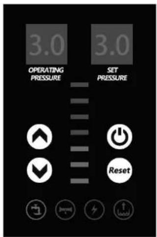

Function of the control indicators


Signals the operation of the pump

Leakage warning indicator light

Power supply warning indicator light

Warning indicator light Dry-running protection

Power indicator
The fewer bars that light up, the more energy-efficient.
10. Maintenance and troubleshooting

Prior to carrying out any maintenance work, the pump must be separated from the electrical mains. If you fail to separate the unit from mains, there is a risk of an inadvertent start of the pump.

We decline any liability for damage caused by inappropriate repair attempts. Any damage caused by inappropriate repair attempts will avoid all warranty claims.
Regular maintenance and careful care reduce the risk of possible malfunctions and help to extend the service life of your appliance.
If the pump is not used for a long period of time, it should be completely emptied. Then rinse the pump with clean water. Allow the pump body to dry out thoroughly to prevent damage caused by corrosion. In the event of frost, water remaining in the pump can cause considerable damage due to freezing.
Store the pump in a dry, frost-proof place.
In the event of malfunctions, first check whether there is an operating error or another cause that is not due to a defect in the appliance - such as a power failure.
The following list shows some possible faults in the appliance, possible causes and tips on how to rectify them. All of the above measures may only be carried out when the pump is disconnected from the power supply. If you are unable to rectify a fault yourself, please contact customer service or your point of sale. Further repairs may only be carried out by qualified personnel. Please note that any damage resulting from improper repair attempts will invalidate all warranty claims and we will not be liable for any resulting damage.
| Malfunction | Possible cause | Solution |
| 1. The pump is not dis-charging any liquid, the motor is not running. | 1. No current.2. Thermal motor protection feature has triggered.3. The capacitor is defective.4. The motor shaft is jamming.5. The electronic pump control is defective.6. The anti-dry-running feature is activated | 1. Please use a device complying with GS (German technical supervisory authority) to check for the presence of voltage (safety information to be observed!). Please verify the correct position of the plug.Separate the pump from the electrical mains, allow the system to cool down, eliminate cause.3. Please contact the customer service department.4. Check the cause; eliminate the reason for the jam- ming of the pump.5. Please contact the customer service department.6. Refer to section 2.2 and 2.3 and chapter 9.3. “Cut- ting out in the case of dry running or absence of water” |
| 2. The motor is running, but the pump is not discharging any liquid. | 1. The pump housing is not filled with liquid.2. Air penetrates into the intake line.3. Suction height and/or discharge height too great. | 1. Fill the pump housing with liquid (please refer to "Putting into operation" section).2. Check to make sure that:a) the connection points of the intake line are tight;b) the inlet opening of the intake line including the check valve (non-return valve) are immersed into the liquids being discharged;c) the check valve (non-return valve) with the filter is tight and not jammed;no siphons (i.e. permanently liquid-filled loops),d) kinks, counter-slopes or narrow spots are present along the intake lines.3. Change the arrangement of the installation so that the suction height and/or discharge height will not exceed the max. value. |
| 3. The pump stops after a short time of operation because the thermal motor protection feature has triggered | 1. The electrical supply does not correspond to the information given on the type plate.2. Pump or intake line are blocked by solids.3. Liquid is too viscous.4. Temperature of liquid or environment is too high. | 1. Please use a device complying with GS (German technical supervisory authority) to check the voltage of the lines of the connection cord (safety information to be observed!).2. Remove possible congestion.3. Pump may not be suitable for this liquid. If feasible, the liquid should be thinned.4. Make sure that the temperature of the liquid being pumped and the environment do not exceed the max. admissible values. |
| 4. The pump stops because the anti-dry-running feature is activated | 1. Refer to section 2.2. + 2.3. | 1. Refer to section 2.2. + 2.3. |
| 5. The pump cuts in and out too frequently. | 1. Permanent loss of very small quantities of liquid (e.g. dripping water tap, leaking hoses or connecting elements).2. Pump control is defective. | 1. Eliminate leakages.2. Please contact the customer service department. |
| 6. The pump does not cut out. | 1. Permanent loss of large quantities of liquid.2. Pump control is defective. | 1. Eliminate leakages.2. Please contact the customer service department. |
| 7. The pump does not reach the desired pressure. | 1. Refer to section 2.2.2. Worn pump wheel. | 1. Refer to section 2.2.2. Please contact the customer service department. |
11. Warranty
The present device was manufactured and inspected according to the latest methods. The seller warrants for faultless material and workmanship in accordance with the legal regulations of the country in which the device was purchased. The warranty period begins with the day of the purchase and is subject to the provisions below: Within the period of warranty, all defects which are to be attributable to defective materials or manufacturing will be eliminated free of charge. Any complaints are to be reported immediately upon their detection.
The warranty claim becomes void in the case of interventions undertaken by the purchaser or by third parties. Damage resulting from improper handling or operation, incorrect setting-up or storage, inappropriate connection or installation or Acts of God or other external influences are excluded from warranty.
Parts being subject to wear and tear, such as the pump wheel (impeller) and mechanical shaft seals are excluded from warranty.
All parts were manufactured using maximum care and high-quality materials and are designed for a long lifecycle. It should be understood, however, that the wear and tear depends on the kind of use, the intensity of use and the internals of maintenance. Complying with the installation and maintenance information contained in the present operating instructions will therefore considerably contribute to a long lifecycle of these wearing parts.
In case of complaints, we reserve the option of repairing or replacing the defective parts or replace the entire device. Replaced parts will pass into our property.
Claims for liquidated damages are excluded unless they are caused by willful acts or negligence on the side of the manufacturer.
The warranty does not provide for any claims beyond those referred to above. The warranty claim has to be evidenced by the purchaser in the form of the submission of the sales receipt. The present warranty commitment is valid in the country in which the device was purchased.
Please note:
- Should your device fail to function properly, please verify first whether an operating error or another cause is present which cannot be attributed to a defect of the device.
- In case you have to take or send in your defective device for repair, please be sure to enclose the following documents:
– Sales receipt (sales slip).
- A description of the occurring defect (a description as accurate as possible will expedite the repair work).
- In case you have to take or send in your defective device for repair, please remove any attached parts which do not belong to the original condition of the device. If any attached parts of this kind should be missing upon the return of the device, we shall not be liable for them.
12. How to order spare parts
The fastest, most simple and cheapest way of ordering spare parts is through the internet. On our www.tip-pumpen.de website you will find a convenient spare part shop where you can order spare parts with just a couple of clicks. In addition, this is also the place where we publish comprehensive information and valuable tips on our products and accessories, introduce new devices and present current trends and innovations in the range of pump technology.
13. Service
In the case of warranty claims or malfunction, please contact your point of sale.
A current operating manual is available as required as a PDF file via e-mail: service@tip-pumpen.de.

For EC countries only
Please do not dispose of electrical appliances in the regular domestic waste!
According to the European Directive 2012/19/EU regarding waste electrical and electronic equipment and the implementation of that directive into national law, electrical devices have to be collected separately and disposed of in an environmental-suitable manner after the end of their life cycle. Should you have any questions, please contact your local waste disposal company.
Chère cliente, cher client,
D
1 Dust cover
2 Safety bracket
3 Non-return valve
4 Pressure tank
5 Fastening screws
6 Pump housing
7 Housing
8 Control panel with electronic control
9 Motor
F
Email: service@tip-pumpen.de
03/2026

- Table of contents
- General safety information
- Range of use
- Scope of delivery
- Assembly
- Installation
- General installation information
- Installation of the pressure line
- Stationary installation
- Using the pump for garden ponds and similar places
- Electrical connection
- Putting into operation
- Function of the pump control / control panel
- General information
- Functionality
- Cutting out in the case of dry running or absence of water
- Setting the pump pressure
- Control panel
- Maintenance and troubleshooting
- Warranty
- Please note:
- How to order spare parts
- Service
- For EC countries only
- D
- F
Brand : T.I.P.
Model : DHWA 5000-5 INV
Category : Pump