
EAP320 - Access Point TP-LINK - Free user manual and instructions
Find the device manual for free EAP320 TP-LINK in PDF.


| Product type | WiFi access point |
| Brand | TP-Link |
| Model | EAP320 |
| Dimensions (L x W x H) | 200 x 200 x 35 mm (estimated) |
| Weight | 0.3 kg (estimated) |
| Power supply | PoE 802.3af or mains adapter (12 V) |
| Interfaces | 1 Ethernet port 10/100/1000 Mbps |
| Main features | WiFi access point, centralized management via EAP Controller, ceiling, wall or rail mounting |
| Maintenance and cleaning | Clean with a soft, dry cloth. Do not use chemical products. |
| Safety | Do not disassemble the device. Do not use near water. Disconnect power to cut off current. |
| Spare parts and repairability | Repair exclusively by TP-Link or an authorized service. Limited warranty included. |
| Management software | EAP Controller (downloadable at www.tp-link.fr) |
| Mounting | Ceiling (on slab or rail) or wall, with mounting kit included |
| PoE power | Compatible with PoE switch or PoE injector |
Frequently Asked Questions - EAP320 TP-LINK
User questions about EAP320 TP-LINK
0 question about this device. Answer the ones you know or ask your own.
Ask a new question about this device
Download the instructions for your Access Point in PDF format for free! Find your manual EAP320 - TP-LINK and take your electronic device back in hand. On this page are published all the documents necessary for the use of your device. EAP320 by TP-LINK.
USER MANUAL EAP320 TP-LINK
South Building(floors 1,3,4,5) and 28(floors 1-4), Central Science & Technology Park, Shennan Rd, Nanshan, Shenzhen, China
Unit 2 & 3 Riverview (142-144), Cardiff Road, Reading, RG1 8EW
TP-LINK Italia S.r.l.
Marathonodromou 77, Marousi 151 24, Greece
NWS.TP-LINK Portugal, Unipessoal, Lda.
Specifications are subject to change without notice. TP-LINK is a registered trademark of
TP-LINK TECHNOLOGIES CO., LTD. Other brands and product names are trademarks or registered trademarks of their respective holders.
No part of the specifications may be reproduced in any form or by any means or used to make any derivative
such as translation, transformation, or adaptation without permission from
TP-LINK TECHNOLOGIES CO., LTD. Copyright © 2016 TP-LINK TECHNOLOGIES CO., LTD. All rights reserved.
www.tp-link.com
Installation Guide
Ceiling Mount Access Point
7106506379 REV1.0.0
Contents
Deutsch ....1
English....7
Español....13
Ελληνικά 19
Français....25
Italiano....31
Português ....37
Suomi 43
Nederlands 49
Svenska....55
Norsk....61
Dansk 67
Türkçe....73
Hardwareinstallation
■ Option 1: Deckenmontage
natural_image
Pure mechanical diagram showing a bracket and lever mechanism without any text or symbolsnatural_image
Technical line drawing of a mechanical latch or switch assembly (no text or symbols)natural_image
Diagram of a sewing machine with attached clamps and a hand pulling the rope (no text or labels)natural_image
Technical line drawing of a mechanical assembly with no visible text or symbolsnatural_image
Diagram of a device with a handle and internal components, showing a blue arrow indicating direction (no text or symbols present)■ Option 2: Deckenmontage
natural_image
Diagram showing a blue arrow pointing downward from a grid of empty cells to a filled blue rectangle (no text or symbols)natural_image
Diagram of a device with multiple sensors and a central display, no text or symbols presentnatural_image
Top-down diagram of a ceiling-mounted device with no visible text or symbolsnatural_image
Technical line drawing of a boat hull with directional arrows indicating flow or movement (no text or symbols)■ Option 3: Wandmontage
natural_image
Four identical blue cylindrical objects with cross marks arranged in a 2x2 grid, placed above a ruler for scale (no text or symbols)natural_image
Pure diagram of a rectangular object with internal lines and corner markers, no text or symbols presentnatural_image
Technical diagram showing a mechanical assembly with two vertical components and a textured surface (no text or symbols)natural_image
Diagram of a mechanical component with a downward arrow indicating force or direction (no text or symbols present)Spannungsversorgung
Note: The image may differ from the actual product.
Network Topology
A typical network topology for the EAP is shown below.

flowchart
graph LR
    A["Controller Host"] --> B["Router Switch"]
    B --> C["EAP"]
    B --> D["EAP"]
    B --> E["EAP"]
    C --> F["Mobile Device"]
    D --> G["Client Interface"]
    E --> H["Client Interface"]
    I["Internet"] --> B
A DHCP server (typically a router) is required to assign IP addresses to the EAPs and clients in your local network. A computer running the EAP Controller software, which can be in the same or different subnet with the EAPs, is used to centrally manage the EAPs.
You can get the EAP Controller software from our website http://www.tp-link.com.
Hardware Installation
■ Option1: Ceiling Rail Mounting
Follow the steps below to install the EAP with the provided accessories:


Ceiling T-rail Clip M3×6 Pan-head Screws (Qty.5)
1 Position the Ceiling T-rail Clip and push the movable part toward the rail base.

natural_image
Pure mechanical diagram showing a vertical bracket and a bracket with a blue arrow indicating direction (no text or symbols)2 Use an M3×6 pan-head screw to secure the T-rail Clip onto the ceiling rail.

natural_image
Technical line drawing of a mechanical latch or bracket with mounting feet and a hanging hook (no text or symbols)3 Attach the mounting bracket to the Ceiling T-rail Clip using four M3x6 pan-head screws.

natural_image
Diagram of a sewing machine with attached clamps and a handle, showing no text or symbols4 Make the Ethernet Cable pass through the fixing hole of the mounting bracket. Connect the cable to the ETHERNET port and attach the EAP to the bracket.

natural_image
Technical line drawing of a mechanical assembly with no visible text or symbols5 Push the EAP along the direction of arrows until it locks into place. Then adjust the cable to make the exposed part hidden behind the EAP.

natural_image
Diagram of a device with a handle and internal components, showing a blue arrow indicating direction (no text or symbols present)■ Option2: Ceiling Mounting
Follow the steps below to install the EAP with the provided accessories:

Washers (Qty.4)

M3×30 Pan-head Screws (Qty.4)

Wing Nuts (Qty.4)
1 Remove the ceiling tile.

natural_image
Diagram showing a blue arrow pointing downward from a grid of empty cells to a filled blue rectangle (no text or symbols)2 Place the mounting bracket in the center of the ceiling tile. Mark the four positions of the screw holes and a hole for the Ethernet cable to feed through. Drill four 4mm holes for the screws and a 10mm hole for the Ethernet cable.

Hole for Ethernet cable
3 Secure the mounting bracket to the ceiling tile using four M3x30 pan-head screws, washers and wing nuts.

natural_image
Diagram of a device with multiple sensors and a central display, showing no text or symbols.4 Feed the Ethernet cable through the hole. Then set the ceiling tile back into place.

natural_image
Top-down diagram of a ceiling-mounted device with control panel and indicator lights (no text or symbols)5 Connect the Ethernet cable to the ETHERNET port and push the EAP along the direction of arrows until it locks into place. Then adjust the cable to make the exposed part hidden behind the EAP.

natural_image
Technical line drawing of a boat hull with directional arrows indicating flow or movement (no text or symbols)■ Option3: Wall Mounting
Follow the steps below to install the EAP with the provided accessories:
Note: We do not recommend you to install the EAP with the Ethernet port upward.

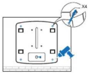
1 If your Ethernet cable feeds through the wall, you can position the mounting bracket to make the cable through the fixing hole. Mark the four positions of the screw holes and then drill four 6mm holes.
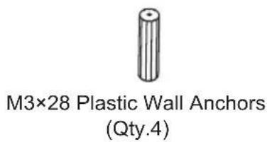
2 Insert the plastic wall anchors into the 6mm holes.

natural_image
Four identical blue screwdrivers arranged in a 2x2 grid on a white background, with a ruler below (no text or symbols)3 Secure the mounting bracket to the wall by driving the self-tapping screws into the anchors. Make sure that the shoulders of the mounting bracket are on the outside.

natural_image
Pure diagram of a rectangular object with internal lines and corner markers, no text or symbols present4 Connect the Ethernet cable to the ETHERNET port on the EAP and attach the EAP to the mounting bracket.

natural_image
Technical diagram showing a mechanical assembly with two vertical components and a textured surface (no text or symbols)5 Push the EAP along the direction of arrows until it locks into place, and then adjust the cable to make the exposed part hidden behind the EAP.

natural_image
Diagram of a mechanical component with a downward arrow indicating force or direction (no text or symbols present)Power Supply
EAP can be powered via a PSE device (such as a PoE switch) or a power adapter.
■ Via PoE Switch
Connect the Ethernet cable from the PoE switch to the ETHERNET port.

■ Via Power Adapter
Plug one end of the provided power adapter into the POWER port of the EAP and the other end to a standard electrical wall outlet.

natural_image
Pure electrical circuit lines without any symbolsnatural_image
Technical line drawing of a mechanical bracket with a blue arrow indicating direction (no text or symbols)natural_image
Technical line drawing of a mechanical latch or bracket with mounting feet and a hanging hook (no text or symbols)natural_image
Diagram of a sewing machine with attached clamps and a hand holding the hook (no text or labels)natural_image
Technical line drawing of a mechanical assembly with no visible text or symbolsnatural_image
Diagram of a device with a handle and internal components, showing a blue arrow indicating direction (no text or symbols present)natural_image
Diagram of a device with multiple sensors and a central display, showing no text or symbols.natural_image
Top-down diagram of a ceiling-mounted device with control panel and indicator lights (no text or symbols)natural_image
Technical line drawing of a mechanical component with no visible text or symbolsnatural_image
Four identical blue screwdrivers arranged in a 2x2 grid on a white background, with a ruler below (no text or symbols)natural_image
Pure diagram of a rectangular object with internal lines and control points, no text or symbols presentnatural_image
Technical diagram showing a mechanical assembly with two parallel plates and a textured wall (no text or symbols)natural_image
Diagram showing a mechanical component with a downward arrow indicating force or direction (no text or symbols present)natural_image
Pure mechanical assembly diagram showing a vertical component with a bracket and a right-angle bracket, no text or symbols present.natural_image
Technical line drawing of a mechanical latch or bracket with mounting feet and a hanging hook (no text or symbols)natural_image
Diagram of a sewing machine with attached clamps and a hand, showing no text or symbolsnatural_image
Technical line drawing of a mechanical assembly with no visible text or symbolsnatural_image
Diagram of a device with a handle and internal components, showing a blue arrow indicating direction (no text or symbols present)natural_image
Diagram showing a blue arrow pointing downward from a grid of empty cells to a filled blue rectangle (no text or symbols)natural_image
Diagram of a device with multiple sensors and a central display, showing no text or symbols.natural_image
Top-down diagram of a ceiling-mounted device with no visible text or symbolsnatural_image
Technical line drawing of a boat hull with directional arrows indicating flow or movement (no text or symbols)natural_image
Four identical blue screwdrivers arranged in a 2x2 grid on a white background, with a ruler below (no text or symbols)natural_image
Pure diagram of a rectangular device with four square holes and a central vertical line, no text or symbols present.natural_image
Technical diagram showing a mechanical assembly with two vertical components and a textured surface (no text or symbols)natural_image
Diagram of a mechanical component with a downward arrow indicating force or direction (no text or symbols present)Τροφοδοσία
natural_image
Pure mechanical diagram of a vertical bracket with a blue arrow indicating direction (no text or symbols)natural_image
Technical line drawing of a mechanical latch or bracket with mounting feet and a hanging hook (no text or symbols)natural_image
Technical line drawing of a mechanical assembly with no visible text or symbolsnatural_image
Diagram of a device with a handle and internal components, showing a blue arrow indicating direction (no text or symbols present)natural_image
Diagram showing a blue arrow pointing downward from a grid of empty cells to a filled blue rectangle (no text or symbols)natural_image
Diagram of a device with multiple sensors and a central display, no text or symbols presentnatural_image
Top-down diagram of a ceiling-mounted device with control panel and indicator lights (no text or symbols)natural_image
Technical line drawing of a boat hull with directional arrows indicating flow or movement (no text or symbols)natural_image
Four identical blue cylindrical objects with cross marks arranged in a 2x2 grid, placed above a ruler for scale (no text or symbols)natural_image
Pure diagram of a rectangular object with internal lines and corner markers, no text or symbols present.natural_image
Technical diagram showing a mechanical assembly with two vertical components and a textured surface (no text or symbols)natural_image
Diagram of a mechanical component with a downward arrow indicating force or direction (no text or symbols present)Alimentation
natural_image
Pure mechanical diagram showing a bracket and lever mechanism without any text or symbolsnatural_image
Technical line drawing of a mechanical latch or bracket with mounting feet and a hanging hook (no text or symbols)natural_image
Diagram of a sewing machine with attached clamps and a hand, showing no text or symbolsnatural_image
Technical line drawing of a mechanical assembly with no visible text or symbolsnatural_image
Diagram of a device with a handle and internal components, showing a blue arrow indicating direction (no text or symbols present)natural_image
Diagram showing a blue arrow pointing downward from a grid of empty cells to a filled blue rectangle (no text or symbols)natural_image
Diagram of a device with multiple sensors and a central display, showing no text or symbols.natural_image
Top-down diagram of a ceiling-mounted device with control panel and indicator lights (no text or symbols)natural_image
Technical line drawing of a mechanical component with no visible text or symbolsnatural_image
Four identical blue screwdrivers arranged in a 2x2 grid on a white background, with a ruler below (no text or symbols)natural_image
Pure diagram of a rectangular object with internal lines and corner markers, no text or symbols presentnatural_image
Technical diagram showing a mechanical assembly with two vertical components and a textured surface (no text or symbols)natural_image
Diagram of a mechanical component with a downward arrow indicating force or direction (no text or symbols present)Alimentazione
natural_image
Technical line drawing of a mechanical latch or switch assembly (no text or symbols)natural_image
Diagram of a sewing machine with attached clamps and a hand pulling the rope (no text or labels)natural_image
Technical line drawing of a mechanical assembly with no visible text or symbolsnatural_image
Diagram of a device with a handle and internal components, showing a blue arrow indicating direction (no text or symbols present)natural_image
Diagram showing a blue arrow pointing downward from a grid of empty cells to a filled blue rectangle (no text or symbols)natural_image
Diagram of a device with four sensors and a central display, showing no text or symbolsnatural_image
Diagram of a ceiling-mounted device with control panel and indicator lights (no text or symbols)natural_image
Technical line drawing of a boat hull with directional arrows indicating movement (no text or symbols)2 Insira as buchas de plástico nos furos de 6mm.

natural_image
Four identical screwdrivers arranged in a 2x2 grid on a ruler background (no text or symbols)natural_image
Pure diagram of a rectangular object with internal lines and corner markers, no text or symbols presentnatural_image
Technical diagram showing a mechanical assembly with two vertical components and a textured surface (no text or symbols)natural_image
Diagram of a mechanical component with a downward arrow indicating force or direction (no text or symbols present)natural_image
Technical line drawing of a mechanical component with mounting holes and a screw (no text or symbols)natural_image
Pure mechanical diagram showing a bracket and lever mechanism without any text or symbolsnatural_image
Technical line drawing of a mechanical latch or bracket with mounting feet and a hanging hook (no text or symbols)natural_image
Diagram of a mechanical device with multiple adjustment knobs and a hand holding a tool (no text or labels)natural_image
Technical line drawing of a mechanical assembly with mounting holes and internal components (no text or symbols)natural_image
Diagram of a device with a handle and internal components, showing a blue arrow indicating direction (no text or symbols present)natural_image
Diagram showing a blue arrow pointing downward from a grid of empty cells to a filled blue rectangle (no text or symbols)natural_image
Diagram of a device with multiple sensors and a central display, showing no text or symbols.natural_image
Top-down diagram of a ceiling-mounted device with control panel and indicator lights (no text or symbols)natural_image
Technical line drawing of a boat hull with directional arrows indicating flow or movement (no text or symbols)natural_image
Four identical blue screwdrivers arranged in a 2x2 grid on a white background, with a ruler below (no text or symbols)natural_image
Pure diagram of a rectangular device with four square holes and a central vertical line, no text or symbols present.natural_image
Technical diagram showing a mechanical assembly with two vertical components and a textured surface (no text or symbols)natural_image
Diagram showing a mechanical component with a blue arrow indicating downward motion (no text or symbols present)Virtalähde
natural_image
Pure electrical circuit lines without any symbolsPlafond T-rail clip M3×6 Kruiskop Schroeven (Aantal.5)
natural_image
Pure mechanical diagram showing a vertical bracket and a right-angle bracket with a blue arrow indicating direction (no text or symbols)natural_image
Technical line drawing of a mechanical latch or bracket with mounting feet and a hanging hook (no text or symbols)natural_image
Diagram of a mechanical device with multiple adjustment knobs and a handle, showing no text or symbols.natural_image
Technical line drawing of a mechanical assembly with no visible text or symbolsnatural_image
Diagram of a device with a handle and internal components, showing a blue arrow indicating direction (no text or symbols present)■ Optie 2: Plafond montage
natural_image
Diagram showing a blue arrow pointing downward from a grid of empty cells to a filled blue rectangle (no text or symbols)natural_image
Diagram of a device with four sensors and a central display, showing no text or symbolsnatural_image
Top-down diagram of a ceiling-mounted control panel with no visible text or symbolsnatural_image
Technical line drawing of a boat hull with directional arrows indicating flow or movement (no text or symbols)natural_image
Four identical screwdrivers arranged in a 2x2 grid with cross marks, placed above a ruler for scale (no text or symbols)natural_image
Pure diagram of a rectangular object with internal lines and corner markers, no text or symbols present.natural_image
Technical diagram showing a mechanical assembly with two components and a textured surface (no text or symbols)natural_image
Diagram of a mechanical component with a downward arrow indicating force or direction (no text or symbols present)Stroomvoorziening
natural_image
Technical line drawing of a mechanical component with mounting holes and a screw (no text or symbols)natural_image
Pure mechanical diagram showing a bracket and mounting bracket without any text, numbers, or symbolsnatural_image
Technical line drawing of a mechanical latch or bracket with mounting feet and a hanging hook (no text or symbols)natural_image
Diagram of a sewing machine with attached clamps and a handle, showing no text or symbolsnatural_image
Technical line drawing of a mechanical assembly with no visible text or symbolsnatural_image
Diagram of a device with a handle and internal components, showing a blue arrow indicating direction (no text or symbols present)■ Alternativ 2: Takmontering
natural_image
Diagram showing a blue arrow pointing downward from a grid of empty cells to a filled rectangle (no text or symbols)natural_image
Diagram of a device with multiple sensors and a central display, no text or symbols presentnatural_image
Top-down diagram of a ceiling-mounted device with control panel and indicator lights (no text or symbols)natural_image
Technical line drawing of a boat hull with directional arrows indicating flow or movement (no text or symbols)■ Alternativ3: Väggmontering
natural_image
Four identical blue screwdrivers arranged in a 2x2 grid on a white background, with a ruler below (no text or symbols)natural_image
Pure diagram of a rectangular object with internal lines and corner markers, no text or symbols present.natural_image
Technical diagram showing a mechanical assembly with two parallel plates and a vertical panel (no text or symbols)natural_image
Diagram of a mechanical component with a downward arrow indicating force or direction (no text or symbols present)Strömförsörjning
EAP kan drivas via en PSE-enhet (t.ex. en PoE-switch) eller en strömadapter.
■ Via PoE Switch
natural_image
Pure electrical circuit lines without any symbolsTakvignolskinne-klemme M3×6 flathodete skruer (5 stk.)
natural_image
Pure mechanical diagram showing a lever mechanism with a blue arrow indicating direction (no text or symbols)natural_image
Technical line drawing of a mechanical latch or switch assembly (no text or symbols)3 Fest monteringsbraketten i takvignolskinneklemmen med fire M3x6 flathodete skruer.

natural_image
Diagram of a sewing machine with attached clamps and a hand pulling the rope (no text or labels)4 Mat Ethernet-kabelen gjennom festehullet på monteringsbraketten. Koble Ethernet-kabelen til ETHERNET-porten på EAP og fest EAP til monteringsbraketten.

natural_image
Technical line drawing of a mechanical assembly with no visible text or symbolsnatural_image
Diagram of a device with a handle and internal components, showing a blue arrow indicating direction (no text or symbols present)■ Alternativ 2: Takmontasje
Hull for Ethernet-kabel
natural_image
Diagram of a device with four sensors and a central display, showing no text or symbolsnatural_image
Top-down diagram of a ceiling-mounted device with control panel and indicator lights (no text or symbols)natural_image
Technical line drawing of a mechanical component with no visible text or symbols■ Alternativ 3: Veggmontasje
natural_image
Four identical blue screwdrivers arranged in a 2x2 grid on a white background, with a ruler below (no text or symbols)natural_image
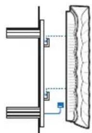
Pure diagram of a rectangular object with internal lines and corner markers, no text or symbols present4 Koble Ethernet-kabelen til ETHERNET-porten på EAP og fest EAP til monteringsbraketten.
natural_image
Technical diagram showing a mechanical assembly with two vertical components and a textured surface (no text or symbols)natural_image
Diagram of a mechanical component with a downward arrow indicating force or direction (no text or symbols present)Strømforsyning
■ Via strømadapter
Hardwareinstallation
natural_image
Technical line drawing of a mechanical component with mounting holes and a screw (no text or symbols)T-skinneklemme M3×6 fladhovedede skruer (antal 5)
natural_image
Pure mechanical diagram showing a bracket and mounting bracket without any text, numbers, or symbolsnatural_image
Technical line drawing of a mechanical latch or switch assembly (no text or symbols)natural_image
Diagram of a sewing machine with attached clamps and a hand pulling the rope (no text or labels)natural_image
Technical line drawing of a mechanical assembly with no visible text or symbolsnatural_image
Diagram of a device with a handle and internal components, showing a blue arrow indicating direction (no text or symbols present)■ Mulighed 2: Loftsmontering
Følg nedenstående trin for at installere EAP'en med det medfølgende tilbehør:
natural_image
Diagram showing a blue arrow pointing downward from a grid of empty cells to a filled blue rectangle (no text or symbols)natural_image
Diagram of a device with multiple sensors and a central display, no text or symbols presentnatural_image
Top-down diagram of a ceiling-mounted device with control panel and indicator lights (no text or symbols)natural_image
Technical line drawing of a mechanical component with directional arrows indicating movement (no text or symbols)natural_image
Four identical blue cylindrical objects with cross marks arranged in a 2x2 grid, placed above a ruler for scale (no text or symbols)natural_image
Pure diagram of a rectangular object with internal lines and corner markers, no text or symbols present.natural_image
Technical diagram showing a mechanical assembly with two parallel plates and a vertical panel (no text or symbols)natural_image
Diagram of a mechanical component with a downward arrow indicating force or direction (no text or symbols present)Strømforsyning
EAP kan strømforsynes via en PSE-enhed (f.eks. en PoE-kontakt) eller en strømadapter.
■ Via PoE Switch
natural_image
Technical line drawing of a mechanical component with mounting holes and a screw (no text or symbols)natural_image
Pure mechanical assembly diagram showing a bracket and mounting bracket without any text or symbolsnatural_image
Technical line drawing of a mechanical latch or bracket with mounting feet and a hanging hook (no text or symbols)natural_image
Diagram of a mechanical device with multiple adjustment knobs and a hand holding a tool (no text or symbols present)natural_image
Technical line drawing of a mechanical assembly with no visible text or symbolsnatural_image
Diagram of a device with a handle and internal components, showing a blue arrow indicating direction (no text or symbols present)natural_image
Diagram showing a blue arrow pointing downward from a grid of empty cells to a filled blue rectangle (no text or symbols)natural_image
Diagram of a device with multiple sensors and a central display, no text or symbols presentnatural_image
Top-down diagram of a ceiling-mounted device with control panel and indicator lights (no text or symbols)natural_image
Technical line drawing of a mechanical component with no visible text or symbols■ Seçenek3: Duvara Montaj
natural_image
Four identical blue screwdrivers arranged in a 2x2 grid on a white background, with a ruler below (no text or symbols)natural_image
Pure diagram of a rectangular object with internal lines and corner markers, no text or symbols present.natural_image
Technical diagram showing a mechanical assembly with two parallel plates and a vertical panel (no text or symbols)natural_image
Diagram of a mechanical component with a downward arrow indicating force or direction (no text or symbols present)Güç Kaynağı
- When a product has a power on/off button, the power on/off button is one way to turn-off the product. For products without the on/off button, the only way to completely turn-off the product is to disconnect the product or the power adapter from the power source. The disconnected device shall remain readily operable.
- Do not open this product or attempt to service it; it may expose you to dangerous high voltage or other risks. Opening a sealed component or sealed product/s will void the warranty. For product servicing, please contact us.
- Do not operate this product near water.
TP-LINK Limited Product Warranty
For TP-LINK Branded Products Only.
THIS WARRANTY GIVES YOU SPECIFIC LEGAL RIGHTS, AND YOU MAY HAVE OTHER RIGHTS THAT VARY FROM STATE TO STATE (OR BY COUNTRY OR PROVINCE).
TO THE EXTENT ALLOWED BY LOCAL LAW, THIS WARRANTY AND THE REMEDIES SET FORTH ARE EXCLUSIVE AND IN LIEU OF ALL OTHER WARRANTIES, REMEDIES AND CONDITIONS.
TP-LINK warrants the TP-LINK branded hardware product contained in the original packaging against defects in materials and workmanship when used normally in according with TP-LINK's guidelines for some period which depends on the local service from the date of original retail purchase by the end-user purchaser.
Español


- Installation Guide
- Contents
- Hardwareinstallation
- ■ Option 1: Deckenmontage
- ■ Option 2: Deckenmontage
- ■ Option 3: Wandmontage
- Spannungsversorgung
- Network Topology
- Hardware Installation
- ■ Option1: Ceiling Rail Mounting
- ■ Option2: Ceiling Mounting
- ■ Option3: Wall Mounting
- Power Supply
- ■ Via PoE Switch
- ■ Via Power Adapter
- Τροφοδοσία
- Alimentation
- Alimentazione
- Virtalähde
- ■ Optie 2: Plafond montage
- Stroomvoorziening
- ■ Alternativ 2: Takmontering
- ■ Alternativ3: Väggmontering
- Strömförsörjning
- ■ Alternativ 2: Takmontasje
- ■ Alternativ 3: Veggmontasje
- Strømforsyning
- ■ Via strømadapter
- ■ Mulighed 2: Loftsmontering
- ■ Seçenek3: Duvara Montaj
- Güç Kaynağı
- TP-LINK Limited Product Warranty
- Español
Brand : TP-LINK
Model : EAP320
Category : Access Point