
929-080 - Wall mount Marquant - Free user manual and instructions
Find the device manual for free 929-080 Marquant in PDF.


| Product type | Wall mount |
| Brand | Marquant |
| Model | 929-080 |
| Compatible TV sizes | 32" to 65" |
| Maximum weight capacity | 50 kg (110 lbs) |
| VESA compatibility | 100x100 mm to 600x400 mm |
| Tilt range | 0 to 10 degrees |
| Wall distance | 20 mm (0.8 in) |
| Material | Heavy-duty cold-rolled steel |
| Surface finish | Black powder coated |
| Dimensions (L x W x H) | 520 x 220 x 30 mm |
| Net weight | 2.8 kg |
| Mounting type | Fixed (low profile) |
| Installation tools required | Stud finder, drill, level, socket wrench (included) |
| Included hardware | Mounting brackets, screws, wall anchors, spacers, level |
| Cable management | Integrated cable clips and cover |
| Safety features | Safety latch, anti-tip design |
| Maintenance | Wipe with dry cloth; check screws periodically |
| Spare parts availability | Screw kits available separately |
Frequently Asked Questions - 929-080 Marquant
User questions about 929-080 Marquant
0 question about this device. Answer the ones you know or ask your own.
Ask a new question about this device
Download the instructions for your Wall mount in PDF format for free! Find your manual 929-080 - Marquant and take your electronic device back in hand. On this page are published all the documents necessary for the use of your device. 929-080 by Marquant.
USER MANUAL 929-080 Marquant
Installation Instructions for Wall Bracket
929-080
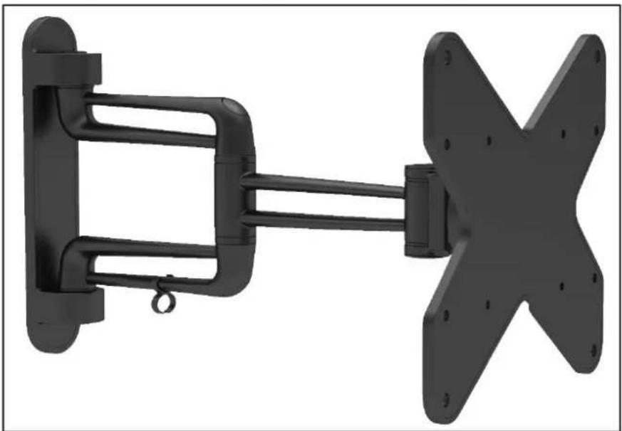
natural_image
3D rendering of a black mechanical assembly with two vertical supports and a central bracket (no text or symbols visible)SV Bruksanvisning i original
NO Bruksanvisning i original
EN Operating instructions in original
SVENSKA 4
SÄKERHETSANVISNINGAR 4
BESKRIVNING 4
Delar 5
Paket M....5
Paket W 5
MONTERING....6
Deler 15
Pakke M....15
Pakke W....15
MONTERING 16
Removal of VESA plate from wall bracket 36
Installation on wooden stud in wall 36
Installation on concrete or brick wall 37
Fitting the decor pieces....38
Fitting the VESA plate....38
Hang up the monitor on the wall bracket 40
Leads and cables....41
Adjusting 42
MAINTÉNANCE 43
SÄKERHETSANVISNINGAR
natural_image
Technical line drawing of a mechanical assembly with two components connected by rods (no text or symbols)Delar
natural_image
Technical line drawing of a mechanical device with spring and housing components (no text or symbols)

natural_image
Four-step diagram showing a brick wall, a pen, a tool, and a power tool (no text or symbols)

natural_image
Technical line drawing of a mechanical arm mounted on a brick wall, showing levers and shafts (no text or symbols)
Märk ut
monteringshälens
placering

Förborra hålen


natural_image
Technical line drawing of a mechanical assembly with two components connected by rods (no text or symbols)Deler
natural_image
Technical line drawing of a mechanical assembly with an inset close-up showing a component labeled 'D' (no text or symbols present)
natural_image
Mechanical assembly diagram showing a motor with spring-loaded housing and a separate view of its mechanical component (no text or symbols present)natural_image
Technical line drawing of a mechanical assembly with spring-loaded components and mounting brackets (no text or symbols)

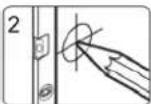

Forhåndsbor
hullene
Marker
monteringshullenes
plassering

natural_image
Four technical illustrations: brick wall, pen, pencil, and power tool (no text or symbols)
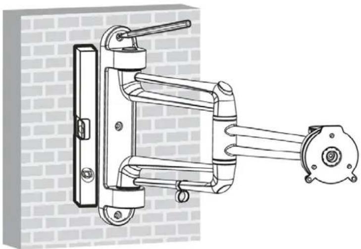
natural_image
Technical line drawing of a mechanical arm assembly mounted on a brick wall (no text or symbols)
Marker
monteringshullenes
plassering

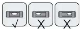
Forhändsbor hullene

natural_image
Technical line drawing of a mechanical assembly with two components connected by rods (no text or symbols)Części

natural_image
Technical line drawing of a mechanical assembly with spring-loaded components and mounting brackets (no text or symbols)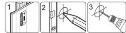
natural_image
Four technical illustrations: brick wall, pen, screwdriver, and power tool (no text or symbols)
natural_image
Technical line drawing of a mechanical linkage assembly mounted on a brick wall (no text or symbols)Read the Installation Instructions carefully before use.
Contact your dealer if you have any questions.
WARNING: Do not exceed the permitted maximum load (max. 20 kg) – risk of serious personal injury and/or material damage.
WARNING:
- Read all the instructions and safety instructions carefully before installation. Contact your dealer if you have any questions.
- The product must only be installed by qualified personnel.
- Check that the wall can support the weight of the bracket and the appliance it is to hold.
- Screw the screws into the middle of any studs.
- Ask another person to help, or use a mechanical lifting device to lift and position the equipment.
- Tighten the screws firmly, but not too hard – risk of material damage.
- The product is only intended for indoor use. Using it outdoors can cause personal injury and/or material damage.
DESCRIPTION

natural_image
Technical line drawing of a mechanical assembly with two components connected by rods (no text or symbols)Parts
IMPORTANT: Check that you have all the parts in the list. Contact your dealer if any parts are missing or damaged.

Package M

M4 × 14 (4)
M-A
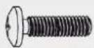
M5 x 14 (4)
M-B

M6 x 14 (4)
M-C
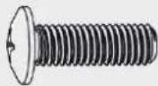
M8 x 20 (4)
M-D

Washer D5 (4)
M-E
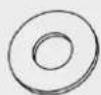
Washer D8 (4)
M-F

Small spacer (8)
M-G
Package W

ST5.5 x 50 (3)
W-A

Concrete anchor (3)
W-B
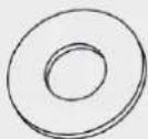
Washer D6 (3)
W-C
INSTALLATION
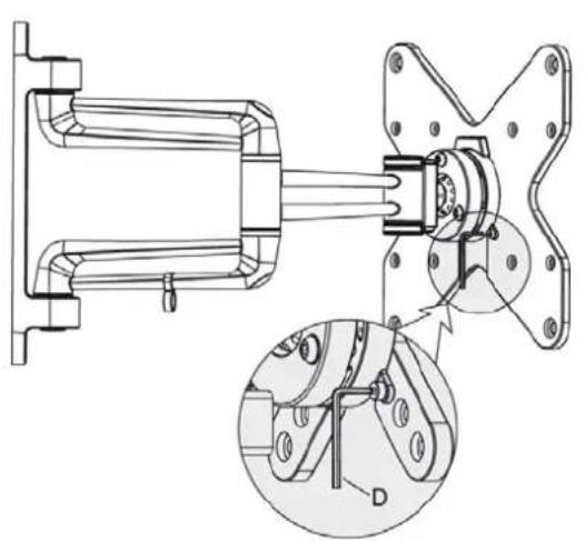
Removal of VESA plate from wall bracket
natural_image
Technical line drawing of a mechanical assembly with an inset close-up showing a component labeled 'D' (no text or symbols present)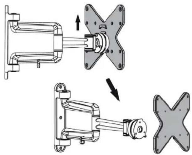
natural_image
Mechanical assembly diagram showing a motor with rotating shafts and mounting flanges, before and after assembly (no text or symbols)Installation on wooden stud in wall



natural_image
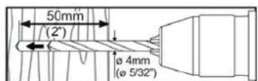
Technical line drawing of a mechanical assembly with spring-loaded components and mounting brackets (no text or symbols)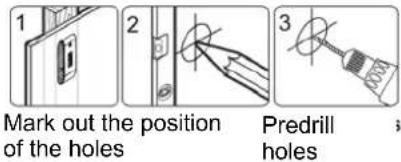

Screw the wall plate to the wall.
WARNING:
- Fasten the screws in the middle of the studs.
- Make sure to use suitable parts for the installation.
- Check that the wall can support the weight of the bracket and the appliance it is to hold.
Installation on concrete or brick wall

natural_image
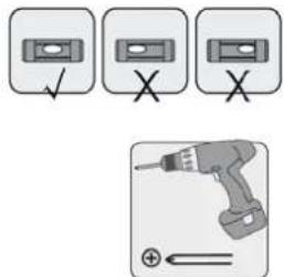
Four technical illustrations: brick wall, pen, screwdriver, and power tool (no text or symbols)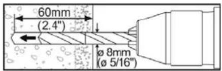

natural_image
Technical line drawing of a mechanical arm assembly mounted on a brick wall (no text or symbols)
Mark out the position of the holes

Predrill the holes


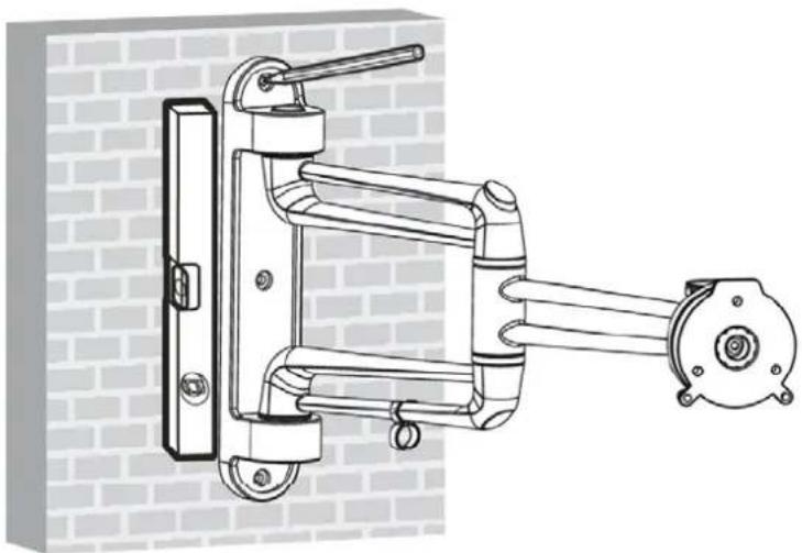
Screw the wall plate to the wall.
WARNING:
- Check that the concrete is at least 35 mm thick to accommodate the concrete anchors. Do not drill into mortar joints. Drill into the bricks or concrete blocks, preferably at least 25 mm from the edge. Drill at low speed, not with the hammer drill function, otherwise this could produce a large hole in the other side of the wall if the drill breaks through.
- Check that the wall can support the weight of the bracket and the appliance it is to hold.
Fitting the decor pieces
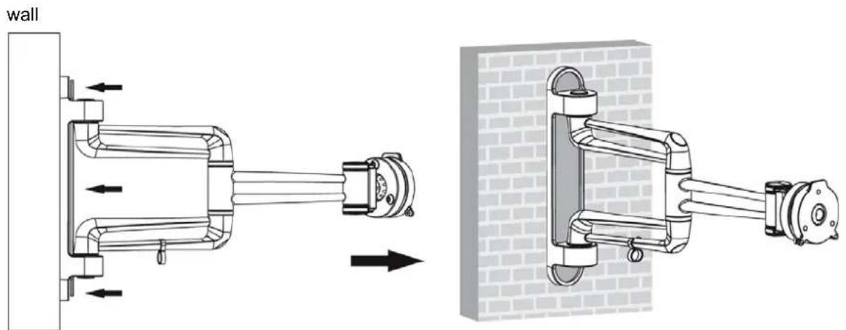
Fit the decor pieces on the wall plate.
Fitting the VESA plate
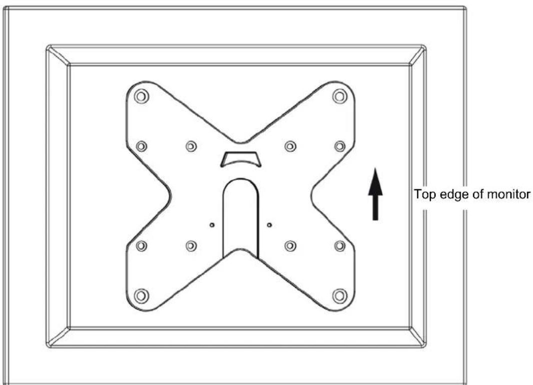

NOTE: Use suitable screws, washers and spacers for the actual monitor model.
- Screw the VESA plate on the monitor.
WARNING: Tighten the screws firmly, but do not overtighten.
Hang up the monitor on the wall bracket
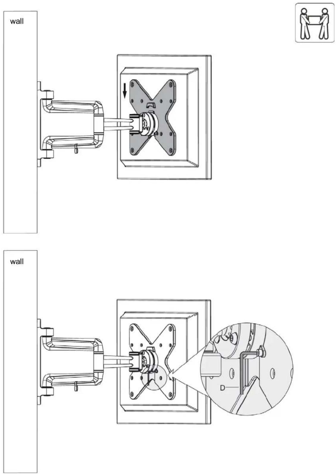
• Carefully lift the monitor and hook the VESA plate on the bracket.
- Lock in place with the screws that were taken out.
Leads and cables

natural_image
Technical line drawing of a mechanical assembly with a wall and housing, showing internal components and wiring (no text or symbols)Connect the cables to the monitor and pull them through the clamp.
NOTE: Leave enough slack cable so that the arm can move.
Adjusting
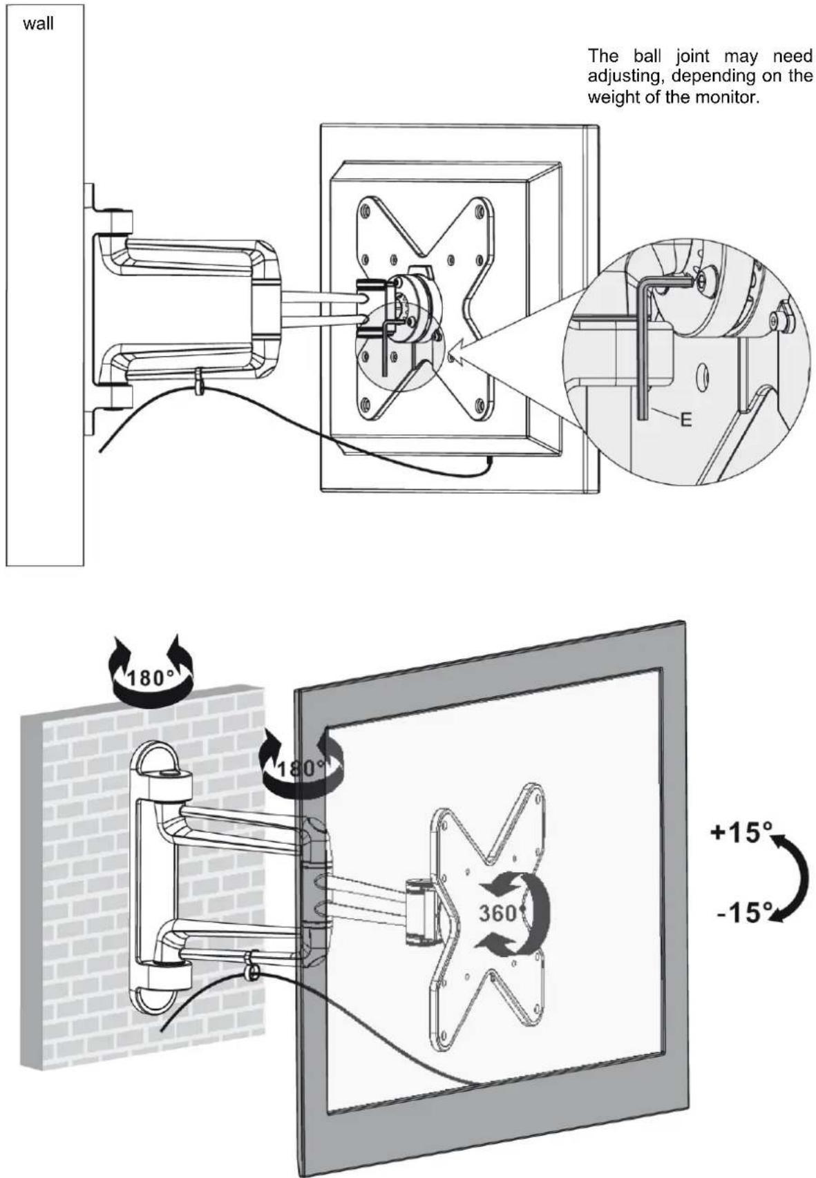
Adjust to the required angle and tilt.
MAINTENANCE
- Check at least every 3 months that the bracket is properly installed.
- Contact your dealer if you have any questions.
Jula reserves the right to make changes. In the event of problems, please contact our service department.
www.jula.com
- SVENSKA 4
- SÄKERHETSANVISNINGAR 4
- BESKRIVNING 4
- MONTERING....6
- MONTERING 16
- SÄKERHETSANVISNINGAR
- Delar
- Deler
- Części
- Read the Installation Instructions carefully before use.
- WARNING:
- DESCRIPTION
- Parts
- Package M
- Package W
- INSTALLATION
- Removal of VESA plate from wall bracket
- Installation on wooden stud in wall
- Installation on concrete or brick wall
- Hang up the monitor on the wall bracket
- Leads and cables
- Adjusting
- MAINTENANCE
Brand : Marquant
Model : 929-080
Category : Wall mount