
929-083 - Wall mount Marquant - Free user manual and instructions
Find the device manual for free 929-083 Marquant in PDF.


| Product Type | Wall Mount |
| Brand | Marquant |
| Model | 929-083 |
| Color | Black |
| Material | Steel |
| Weight Capacity | 30 kg (66 lbs) |
| VESA Compatibility | 200x200 to 400x400 mm |
| Tilt Adjustment | -5° to +15° |
| Level Adjustment | Yes, ±3° |
| Distance from Wall | 2.5 cm (1 inch) |
| Suitable Screen Size | 26" to 65" |
| Installation Type | Fixed to wall studs |
| Included Hardware | Screws, anchors, spacers, bubble level |
| Warranty | 1 year |
Frequently Asked Questions - 929-083 Marquant
User questions about 929-083 Marquant
0 question about this device. Answer the ones you know or ask your own.
Ask a new question about this device
Download the instructions for your Wall mount in PDF format for free! Find your manual 929-083 - Marquant and take your electronic device back in hand. On this page are published all the documents necessary for the use of your device. 929-083 by Marquant.
USER MANUAL 929-083 Marquant
natural_image
Exterior view of a wall-mounted mechanical device with metallic and black components (no text or symbols visible)SE Bruksanvisning för väggfäste
NO Bruksanvisning for veggfeste
PL Instrukcja obsługi uchwytu ściennego
EN User instructions for wall mount bracket
SE - Bruksanvisning i original
NO - Bruksanvisning i original
EN - Operating instructions in original
Date of production: 2014-08-04
© Jula AB
SVENSKA....4
SÄKERHETSANVISNINGAR....4
TEKNISKA DATA....4
MONTERING....5
NORSK 16
SIKKERHETSANVISNINGER 16
TEKNISKE DATA 16
MONTERING 17
POLSKI 28
ZASADY BEZPIECZEŃSTWA 28
DANE TECHNICZNE 28
MONTAŻ 29
ENGLISH 40
SAFETY INSTRUCTIONS 40
TECHNICAL DATA 40
INSTALLATION 41
SÄKERHETSANVISNINGAR
natural_image
Technical illustration of mechanical assembly with two views (top and side), showing internal components and directional arrows (no text or symbols)- Lossa de övre vreden.
- Lossa därefter de undre vreden.
- Ta bort VESA-plattan.
Ta bort höljena
2

natural_image
Diagram showing two mechanical arms with arrows indicating force or movement, no text or symbols presentnatural_image
Technical line drawing of a hand operating a lock mechanism inside a wall frame (no text or symbols)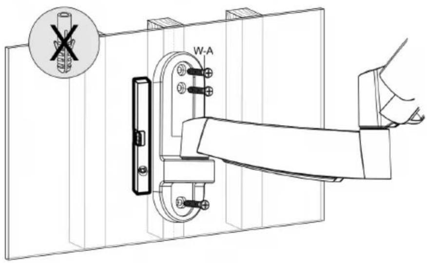

natural_image
Technical line drawing of a mechanical clamp or bracket assembly with a hand operating it (no text or symbols present)
Fäst höljerna
4

natural_image
Two-step diagram showing hand positioning of a door handle mechanism, with arrows indicating movement direction (no text or symbols)montera VESA-adaptrarna
5
VESA 300x300, 400x400 (mm)
VESA 400x200 (mm)

Installera VESA-plattan
oBS!
6B
natural_image
Technical line drawing of a mechanical component with four arms and a central hub, shown in two circular views (no text or symbols)natural_image
Technical line drawing showing a mounted device with four blades and wiring, connected to a handheld device (no text or symbols present)natural_image
Technical line drawing of a four-bladed mechanical component mounted on a rectangular frame (no text or symbols)
natural_image
Mechanical assembly diagram showing a bracket with two bolts and a labeled component E (no text or symbols beyond label)
Justering
natural_image
Technical illustration of mechanical components with no visible text or symbolsnatural_image
Technical illustration of two mechanical arms with arrows indicating movement, showing a close-up of the end (no text or symbols present)natural_image
Technical line drawing of a hand operating a lock mechanism inside a wall-mounted frame (no text or symbols)

ADVARSEL!
natural_image
Technical line drawing of a mechanical clamp or bracket assembly with a hand holding a handle (no text or symbols present)

monter VESA-adapterne
4

natural_image
Two-step diagram showing hand positioning of a door handle mechanism, with arrows indicating movement direction (no text or symbols)Installer VESA-platen
5
VESA 300x300, 400x400 (mm)

VESA 400x200 (mm)

mERK

6B
natural_image
Technical line drawing of a mechanical component with four arms and a central hub, shown in two circular views (no text or symbols)natural_image
Technical line drawing showing a mounted device with four blades and wiring, connected to a handheld device (no text or symbols present)natural_image
Technical line drawing of a four-blade fan mounted on a rectangular frame (no text or symbols)
natural_image
Mechanical assembly diagram showing a bracket with two bolts and a labeled component E (no text or symbols beyond label)
Justering
natural_image
Technical illustration of mechanical components with no visible text or symbolsnatural_image
Technical illustration of two mechanical arms with arrows indicating movement, no text or symbols presentnatural_image
Technical line drawing of a hand operating a lock mechanism inside a wall-mounted frame (no text or symbols)
natural_image
Technical line drawing of a mechanical clamp or bracket assembly with a hand operating it (no text or symbols present)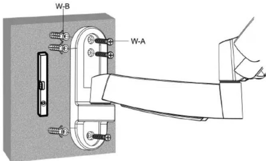

Usuń opakowanie
4

natural_image
Two-step diagram showing hand positioning of a door handle mechanism, with arrows indicating movement direction (no text or symbols)Zamontuj adaptery VESA
5
VESA 300x300, 400x400 (mm)
VESA 400x200 (mm)


6B
natural_image
Technical line drawing of a mechanical component with four arms and a central hub, shown in two circular views (no text or symbols)natural_image
Technical line drawing showing a mounted device with four blades and wiring, connected to a handheld device (no text or symbols present)natural_image
Technical line drawing of a four-blade fan mounted on a rectangular frame (no text or symbols)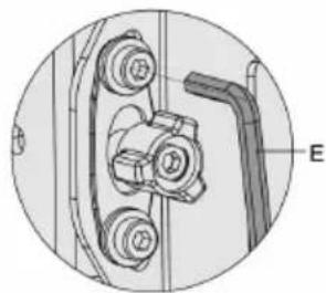
natural_image
Mechanical assembly diagram showing a bracket with two bolts and a labeled component E (no text or symbols beyond label)
Regulacja
Read the operating instructions carefully before use!
Please retain for future reference.
- Check that the bracket is secure and safe to use at regular intervals (at least every three months).
WARNING!
- Any use with products heavier than the rated maximum load indicated may result in personal injury or material damage.
- Do not begin the installation until you have read and understood all the instructions and warnings contained in this installation sheet. If you have any questions regarding the content, please contact your local distributor.
- This wall mount bracket was designed to be installed and utilised ONLY as described in these instructions. Improper installation of this wall mount bracket may cause material damage or serious injury.
- This wall mount bracket should only be installed by someone with good mechanical ability who has basic building experience and fully understands these instructions.
- Make sure that the wall can support the combined weight of the mount bracket and the equipment it is attached to.
- Mounting on wood studs: make sure that mounting screws are anchored at the centre of the studs. The use of a wall stud finder is recommended.
- Always use assistance or mechanical lifting equipment to lift and position the wall mount bracket.
- Tighten screws firmly, but do not overtighten. Overtightening screws may cause damage to the wall mount bracket thereby greatly reducing its holding force.
- This wall mount bracket is intended for indoor use only. Using this wall mount bracket outdoors could lead to material damage and personal injury.
TECHNICAL DATA
Maximum weight 20 kg
Fits screen sizes 26"-47"
INSTALLATION

A. Articulated arm
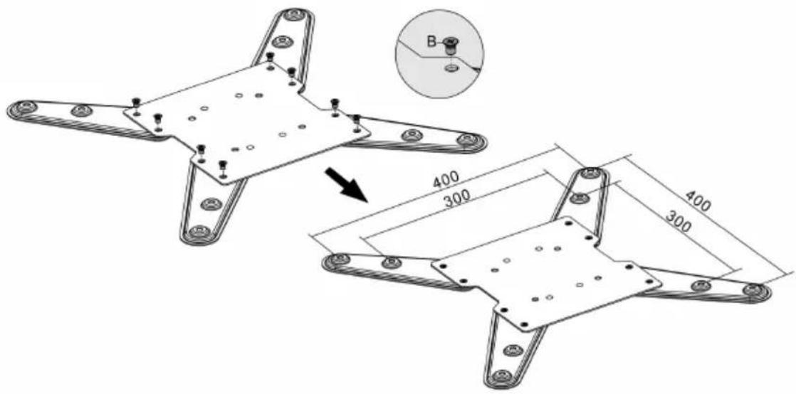
B. M6 (x8)
C. VESA adaptor (x2)
D. VESA adaptor (x2)
E. 4 mm Allen key (x1)
F. 6 mm Allen key (x1)
G. Spanner (x1)
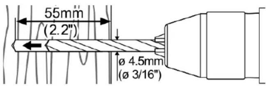
W-A. ST6.3 X 55 (x3)
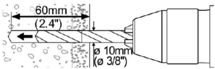
W-B. concrete plug (x3)
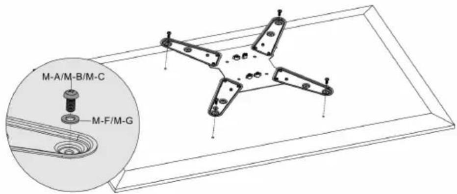
M-A. M5×14 (×4)
M-B. M6x14 (x4)
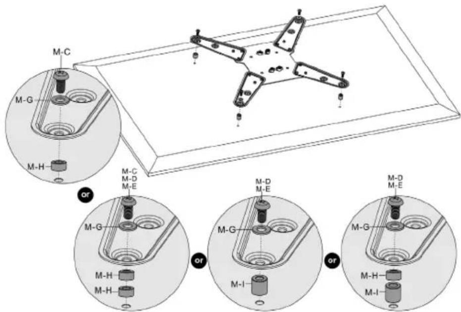
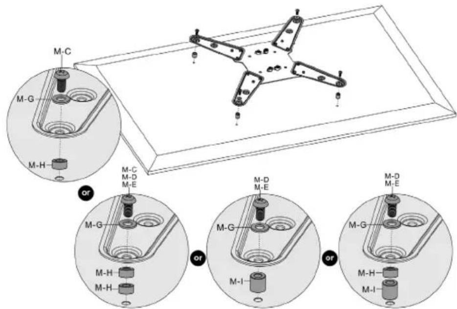
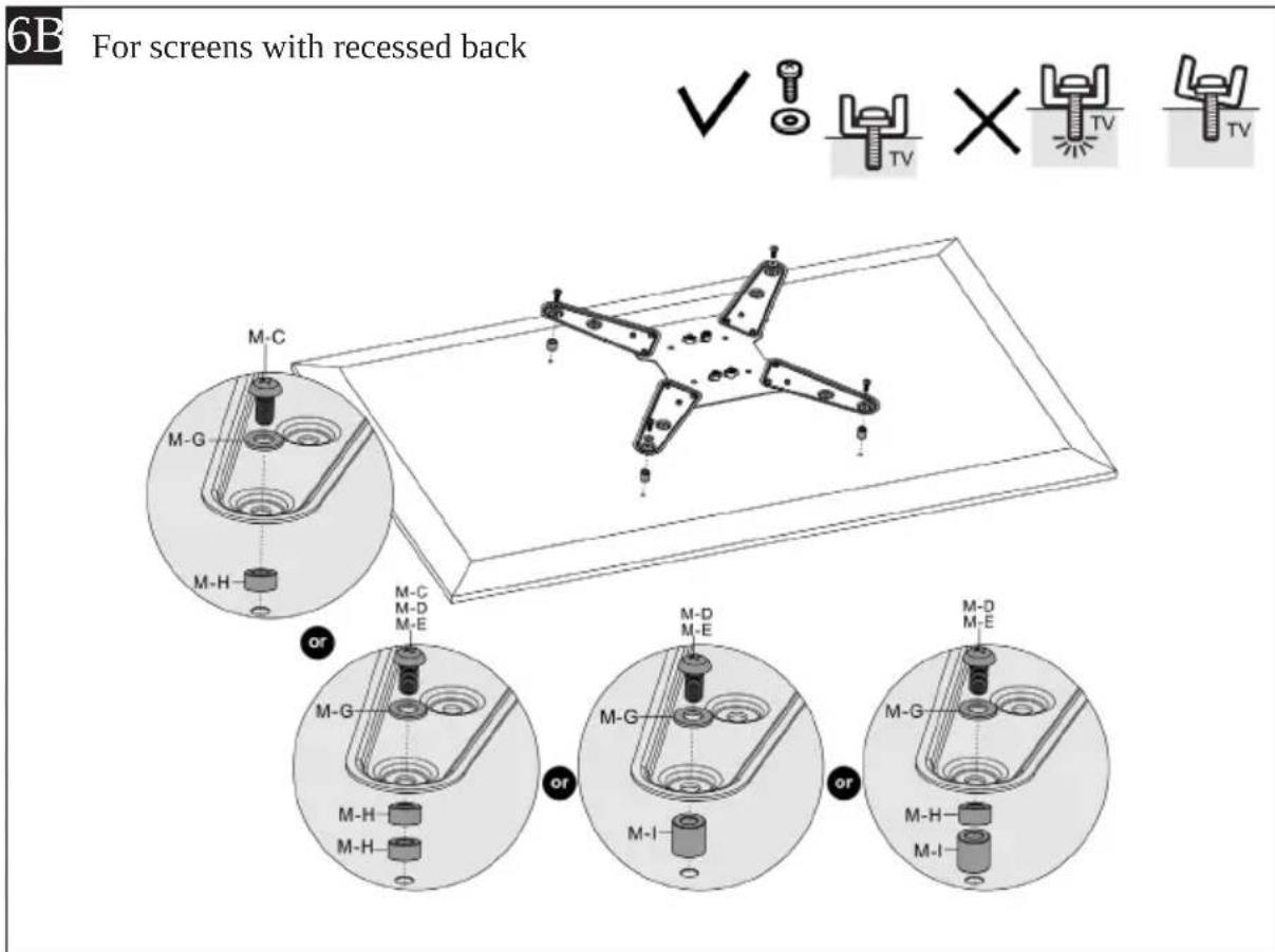
M-C. M8x20 (x4)
M-D. M6x30 (x4)
M-E. M8x30 (x4)
M-F. D5 washer (x4)
M-G. D8 washer (x4)
M-H. Small spacer (x4)
M-1. Large spacer (x4)
Separating the VESA Plate from the Wall Mount Bracket
1

natural_image
Technical illustration of mechanical components with no visible text or symbols- Loosen the upper knobs.
- Then loosen the lower knobs.
- Remove the VESA plate.
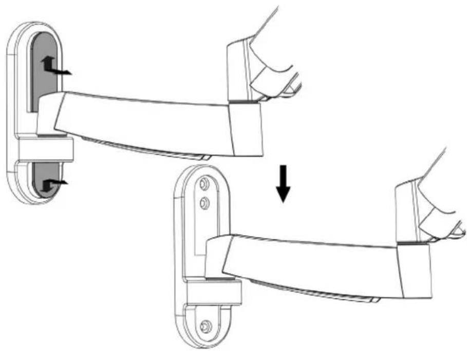
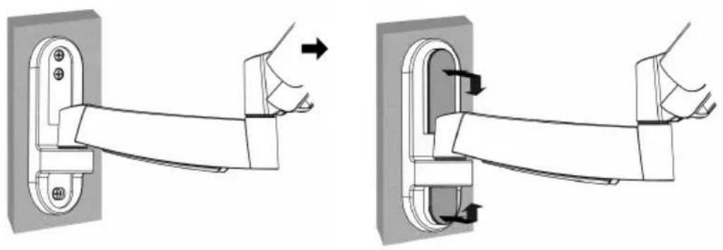
Remove the arm casings
2
natural_image
Technical illustration of two mechanical arms with arrows indicating movement, showing a close-up of the end (no text or symbols present)mounting on wood stud walls
WARNING!
- Make sure that mounting screws are anchored at the centre of the wall stud. The use of a wall stud finder is recommended.
- The installer is responsible for providing tools for other types of mounting situations. The installer must make sure that the wall will safely support the combined weight of the wall mount bracket and all attached hardware and components.
3A

natural_image
Technical line drawing of a hand operating a lock mechanism inside a wall-mounted frame (no text or symbols)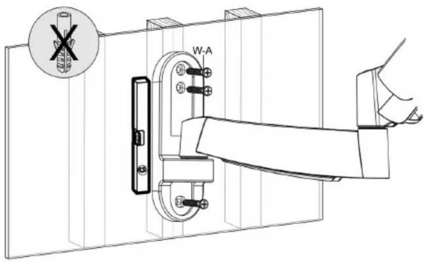

mounting on a concrete or brick wall
WARNING!
- The installer must verify that the wall will safely support the total weight of the wall mount bracket together with all other hardware and components.
3B

natural_image
Technical line drawing of a mechanical clamp or bracket assembly with a hand operating the lever (no text or symbols present)

Refit the arm casings
4
natural_image
Two-step diagram showing hand positioning of a door handle mechanism, with arrows indicating movement direction (no text or symbols)Fit the VESA adaptors
5
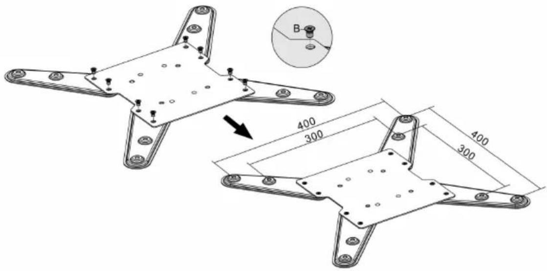
VESA 300 x 300, 400 x 400 (mm)

VESA 400 x 200 (mm)

Installing the VESA plate
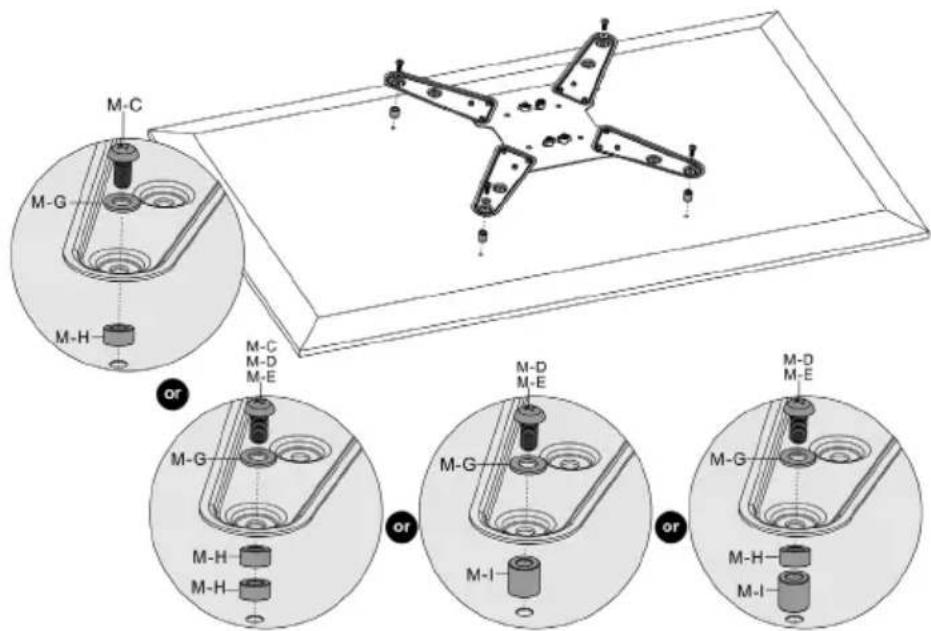
Note:
- Choose screws, washers and spacers (as needed) according to the type of screen.
- Position the VESA plate as close as possible to the centre of the TV.
- Screw the VESA plate onto the TV.
- Tighten all screws but do not overtighten.

Placing the TV on the wall mount bracket
7

- Loosen the upper knobs leaving a 4 mm space to the VESA plate.
- Place the TV on the wall mount bracket.
8

natural_image
Technical line drawing of a mechanical component with four arms and a central hub, shown in two circular views (no text or symbols)• Make sure that the TV is level.
- Place the lower knobs in position and tighten all knobs.
Adjusting the tension
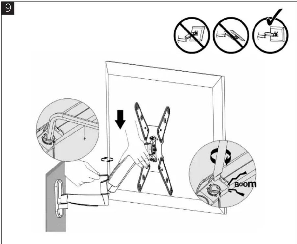
- Keep the arm straight when adjusting tension. Use an Allen key to loosen or tighten the adjustment screw based on the weight of the TV.
- If the TV drops on its own: rotate the adjustment screw towards the "+" symbol.
- If the TV rises on its own: rotate the adjustment screw towards the "-" symbol.
- Tighten the adjustment screws if the joints make popping sounds when in use.
Cable Management
8

natural_image
Technical line drawing showing a mounted device with four blades and wiring, connected to a handheld cable (no text or symbols present)- Connect the cables to the TV, and press in the cable casing to route the cables through the space in the bracket arm.
Note: Leave slack in the cable to allow the bracket arm to move.
9

natural_image
Technical line drawing of a four-blade fan mounted on a rectangular base (no text or symbols)
natural_image
Mechanical assembly diagram showing a bracket with labeled component E (no text or symbols beyond label)
Adjustment
- Tighten the screws using an Allen key (or tighten the knob) until the viewing angle is steady.
- Adjust to the desired position or angle by tilting or making a vertical adjustment.
Jula reserves the right to make changes. In the event of problems, please contact our service department by phoning
0200-88 55 88.
Jula AB, Box 363, 532 24 SKARA
www.jula.se
- SVENSKA....4
- SÄKERHETSANVISNINGAR....4
- TEKNISKA DATA....4
- MONTERING....5
- NORSK 16
- SIKKERHETSANVISNINGER 16
- TEKNISKE DATA 16
- MONTERING 17
- POLSKI 28
- ZASADY BEZPIECZEŃSTWA 28
- DANE TECHNICZNE 28
- MONTAŻ 29
- ENGLISH 40
- SAFETY INSTRUCTIONS 40
- TECHNICAL DATA 40
- INSTALLATION 41
- SÄKERHETSANVISNINGAR
- Ta bort höljena
- Fäst höljerna
- montera VESA-adaptrarna
- Installera VESA-plattan
- oBS!
- 6B
- Justering
- ADVARSEL!
- monter VESA-adapterne
- Installer VESA-platen
- mERK
- Usuń opakowanie
- Zamontuj adaptery VESA
- Regulacja
- Read the operating instructions carefully before use!
- WARNING!
- TECHNICAL DATA
- INSTALLATION
- Separating the VESA Plate from the Wall Mount Bracket
- Remove the arm casings
- mounting on wood stud walls
- mounting on a concrete or brick wall
- Refit the arm casings
- Fit the VESA adaptors
- Installing the VESA plate
- Note:
- Placing the TV on the wall mount bracket
- Adjusting the tension
- Cable Management
- Adjustment
Brand : Marquant
Model : 929-083
Category : Wall mount