
DD 9963 - Range hood AEG-ELECTROLUX - Free user manual and instructions
Find the device manual for free DD 9963 AEG-ELECTROLUX in PDF.


| Product Type | Range Hood |
| Brand | AEG-Electrolux |
| Model | DD 9963 |
| Installation Type | Ducted or Recirculation (with optional charcoal filter) |
| Minimum Safety Distance from Cooktop | 650 mm |
| Exhaust Connection Diameter | 120 mm or 150 mm (with reducer flange) |
| Power Supply | 230-240 V ~ 50 Hz (typical, check rating plate) |
| Motor Speeds | 3 speeds + intensive speed (5 min timed) |
| Auto Shut-Off | Delayed shutdown: 10 min (speed 3), 15 min (speed 2), 20 min (speed 1) |
| Lighting | 1 x 20 W halogen lamp |
| Controls | Electronic push buttons with LED indicators |
| Filter Type (Grease) | Self-bearing metal grease filters, dishwasher safe |
| Filter Type (Odor) | Activated charcoal filter (recirculation version, replace every 4 months) |
| Filter Saturation Alarm | LED indicator: fixed after 100h (grease), flashing after 200h (charcoal) |
| Material | Stainless steel and painted steel (estimated) |
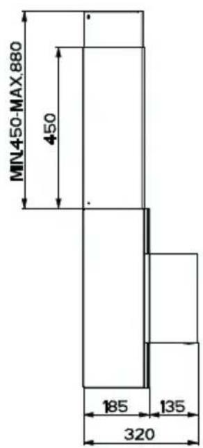
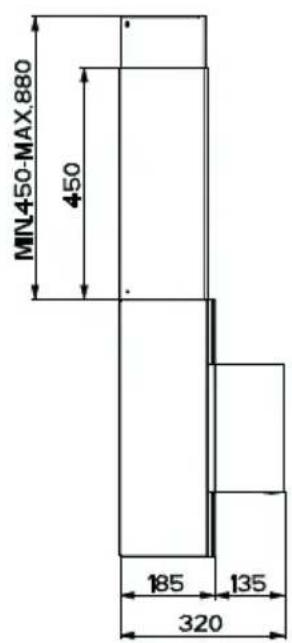
| Dimensions (Overall) | Width: approx. 90 cm (common size), refer to manual |
| Net Weight | Approx. 15-20 kg (estimate for similar models) |
| Energy Class | Not specified, likely B or C (older model) |
| Noise Level | Not specified, typically 55-65 dB(A) |
| Safety Features | Class I, earthing required, two-pole switch with 3 mm contact gap |
Frequently Asked Questions - DD 9963 AEG-ELECTROLUX
User questions about DD 9963 AEG-ELECTROLUX
0 question about this device. Answer the ones you know or ask your own.
Ask a new question about this device
Download the instructions for your Range hood in PDF format for free! Find your manual DD 9963 - AEG-ELECTROLUX and take your electronic device back in hand. On this page are published all the documents necessary for the use of your device. DD 9963 by AEG-ELECTROLUX.
USER MANUAL DD 9963 AEG-ELECTROLUX
natural_image
Isometric line drawing of a mechanical assembly with two stacked components (no text or symbols)INHALTSVERZEICHNIS
DE
RECOMMENDATIONS AND SUGGESTIONS....13
CHARACTERISTICS....14
INSTALLATION 16
USE....19
MAINTENANCE....20
INHOUDSOPGAVE
NL
ADVIEZEN EN SUGGESTIES 22
EIGENSCHAPPEN....23
INSTALLATIE 25
GEBRUIK....28
ONDERHOUD 29
INDICE
IT
CONSIGLI E SUGGERIMENTI ....31
CARATTERISTICHE 32
INSTALLAZIONE....34
USO 37
MANUTENZIONE 38
INNEHÅLL
SE
REKOMMENDATIONER OCH TIPS....40
EGENSKAPER 41
INSTALLATION 43
ANVÄNDING....46
UNDERHÄLL 47
INNHOLD
NO
ANBEFALINGER OG FORSLAG 49
EGENSKAPER 50
INSTALLASJON 52
BRUK 55
VEDLIKEHOLD 56
INDHOLD
DK
RÅD OG ANVISNINGER....58
APPARATBESKRIVELSE 59
INSTALLATION 61
BRUG....64
VEDLIGEHOLDELSE 65
SISÄLTÖ
FI
OHJEET JA SUOSITUKSET 67
MITAT JA OSAT 68
ASENNUS....70
KÄYTTÖ....73
HUOLTO 74
natural_image
Illustration of a chemical experiment setup with a conical flask, thermometer, and smokestack (no text or symbols)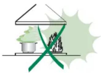
natural_image
Illustration of a greenhouse with a stove and a flame, crossed by a green diagonal line (no text or symbols)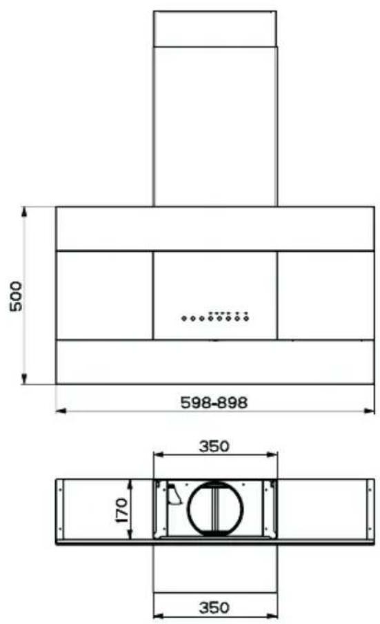

Anschlüss in abluftversion
natural_image
Diagram showing a mechanical component with a green arrow indicating direction, no text or symbols present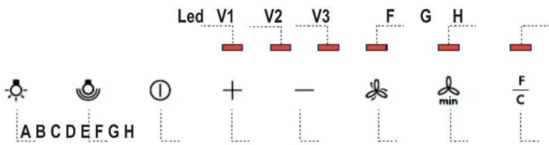
Schalttafel
natural_image
Illustration of a hand pointing at a grid-based device with a yellow arrow indicating rotation (no text or symbols)natural_image
Line drawing of a hand holding a pocket watch with a green flag above it (no text or symbols)The Instructions for Use apply to several versions of this appliance. Accordingly, you may find descriptions of individual features that do not apply to your specific appliance.
INSTALLATION
- The manufacturer will not be held liable for any damages resulting from incorrect or improper installation.
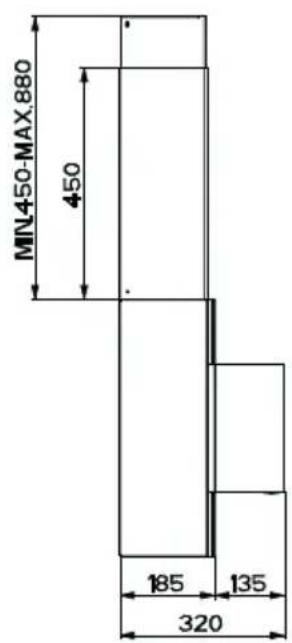
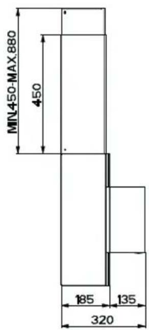
- The minimum safety distance between the cooker top and the extractor hood is 650 mm.
- Check that the mains voltage corresponds to that indicated on the rating plate fixed to the inside of the hood.
- For Class I appliances, check that the domestic power supply guarantees adequate earthing.
Connect the extractor to the exhaust flue through a pipe of minimum diameter 120 mm. The route of the flue must be as short as possible.
- Do not connect the extractor hood to exhaust ducts carrying combustion fumes (boilers, fireplaces, etc.).
- If the extractor is used in conjunction with non-electrical appliances (e.g. gas burning appliances), a sufficient degree of aeration must be guaranteed in the room in order to prevent the backflow of exhaust gas. The kitchen must have an opening communicating directly with the open air in order to guarantee the entry of clean air.
USE
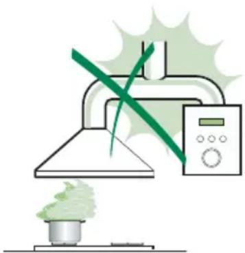
- The extractor hood has been designed exclusively for domestic use to eliminate kitchen smells.
- Never use the hood for purposes other than for which it has been designed.
- Never leave high naked flames under the hood when it is in operation.
- Adjust the flame intensity to direct it onto the bottom of the pan only, making sure that it does not engulf the sides.
- Deep fat fryers must be continuously monitored during use: overheated oil can burst into flames.
- Do not flambè under the range hood; risk of fire
- This appliance is not intended for use by persons (including children) with reduced physical, sensory or mental capabilities, or lack of experience and knowledge, unless they have been given supervision or instruction concerning use of the appliance by a person responsible for their safety.
- Children should be supervised to ensure that they do not play with the appliance.
MAINTENANCE
- Switch off or unplug the appliance from the mains supply before carrying out any maintenance work.
- Clean and/or replace the Filters after the specified time period.
- Clean the hood using a damp cloth and a neutral liquid detergent.
natural_image
Illustration of a kitchen induction setup with a smokestack emitting vapor and a green X-shaped warning symbol (no text or symbols present)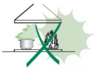
natural_image
Illustration of a greenhouse with a pot and smokestack emitting vapor, crossed by a green ribbon (no text or symbols)The symbol / on the product or on its packaging indicates that this product may not be treated as household waste. Instead it shall be handed over to the applicable collection point for the recycling of electrical and electronic equipment. By ensuring this product is disposed of correctly, you will help prevent potential negative consequences for the environment and human health, which could otherwise be caused by inappropriate waste handling of this product. For more detailed information about recycling of this product, please contact your local city office, your household waste disposal service or the shop where you purchased the product.
Components
Ref. Q.ty Product Components
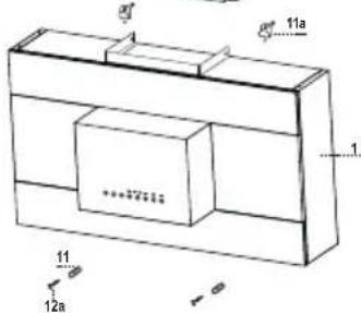
1 1 Hood Body, complete with: Controls, Light, Blower, Filters
2.1 1 Upper Section
2.2 1 Lower Section
9 1 Flange
16 1 Filter cover
Ref. Q.ty Installation Components
7.2.1 2 Upper Chimney Section Fixing Brackets
11 6 Wall Plugs
11a 2 Wall Plugs SB 12/10
12a 6 Screws 4,2 x 44,4
12c 10 Screws 2,9 x 6,5
Q.ty Documentation
1 Instruction Manual

Wall drilling and bracket fixing

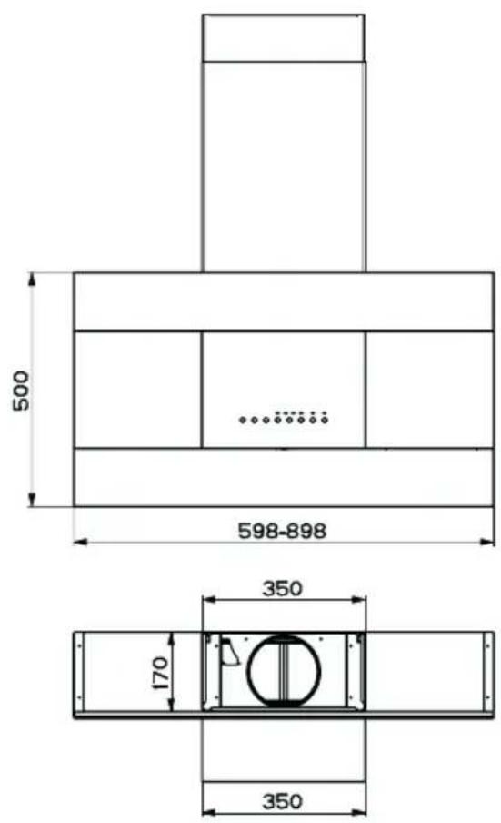
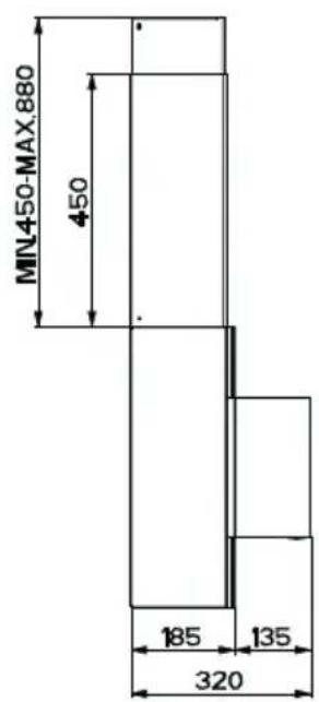
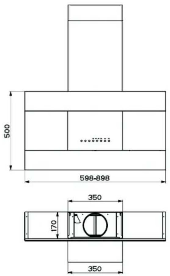
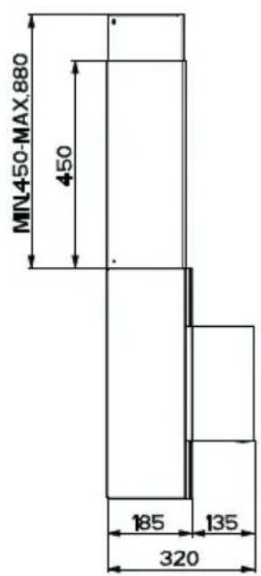
When installing the hood in recycling version it has to be taken into consideration that space remaining between the hood and the upper limit (ceiling or self) is at least 8-10 cm.
As a first step, proceed with the following drawings:
- a vertical line up to the ceiling or up to the upper limit, at the centre of the area in which the hood is to be fitted:
- a horizontal line at a minimum 1090 mm above the cooker top.
- Mark a point (1) on the horizontal line, Y mm to the right of the vertical reference line.
- Repeat this operation on the other side, checking that the two marks are levelled.
- Mark a reference point (2) as indicated at 150 mm from the vertical reference line and 820 mm above the cooker top.
- Repeat this operation on the other side, checking that the two marks are levelled.
- Drill at the marked points (1), using a 12 mm drill bit.
- Drill at the marked points (2), using a 8 mm drill bit.
- Insert the bracket plugs 11a into the holes (1) and tighten the screws.
- Insert plug 11 into holes (2).
- Place bracket 7.2.1 on the wall, about 1-2 mm from the ceiling or from the upper limit, aligning the centre (notch) with the vertical reference line.
- Mark the wall at the centres of the bracket holes.
- Place the bracket 7.2.1 on the wall at X mm below the first bracket (X = height of the upper chimney section), aligning the centre (notch) with the vertical line.
- Mark the wall at the centres of the bracket holes.
- Drill 8 mm holes at all the marked centre points.
- Insert the wall plugs 11 in the holes.
- Fix the brackets using the 12a screws (4,2 x 44,4) supplied with the hood.
Mounting the hood body
- Remove the metal grease filters by turning the handles provided.
- Adjust the two screws Vr, on brackets 11a, to a minimum.
- Hook the hood canopy onto the two brackets 11a.
- From inside the hood canopy, adjust the screws Vr to set the Hood Canopy level.
- Tighten the safety screws 12a.

Connections
DUCTED VERSION AIR EXHAUST SYSTEM
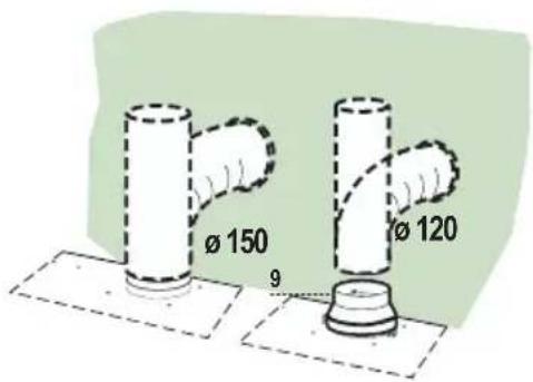
When installing the ducted version, connect the hood to the chimney using either a flexible or rigid pipe 150 or 120 mm, the choice of which is left to the installer.
- To install a 120 mm air exhaust connection, insert the reducer flange 9 on the hood body outlet.
- Fix the pipe in position using sufficient pipe clamps (not supplied).
- Remove possible charcoal filters.
RECYCLING VERSION AIR OUTLET
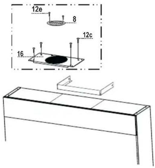
To install the hood in recycling version, the optional charcoal filter kit must be purchased.
- Remove the chimney angle bracket.
- Screw the filter cover onto the air outlet, using four screws 12c (2.9 x 12.5).
Flue assembly
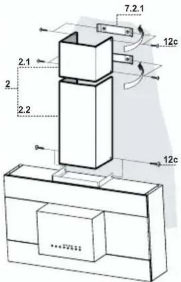
The chimney can only be installed with exhausting hood.
Upper exhaust flue
- Slightly widen the two sides of the upper flue and hook them behind the brackets 7.2.1, making sure that they are well seated.
- Secure the sides to the brackets using the 4 screws 12c (2,9 x 6,5) supplied.
Lower exhaust flue
- Slightly widen the two sides of the flue and hook them between the upper flue and the wall, making sure that they are well seated.
- Fix the lower part laterally to the hood body using the 2 screws 12c (2,9 x 6,5) supplied.
ELECTRICAL CONNECTION
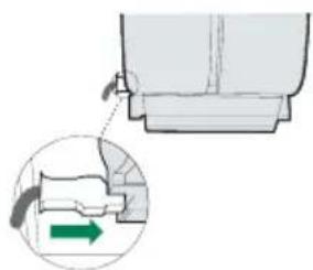
- Connect the hood to the mains through a two-pole switch having a contact gap of at least 3 mm.
- Remove the grease filters (see paragraph Maintenance) being sure that the connector of the feeding cable is correctly inserted in the socket placed on the side of the fan.
natural_image
Diagram showing a mechanical component with a green arrow indicating direction, no text or symbols present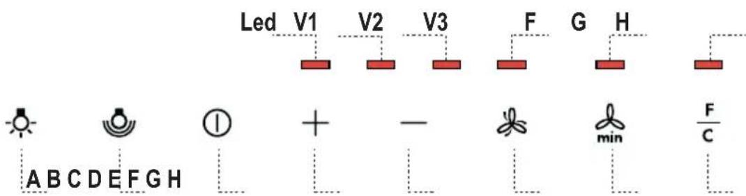
Control panel
| Button | Function LED | |
| A | Turns the lighting system on and off. - | |
| B | Turns the reduced intensity lighting system on and off. | - |
| C | Turns the suction motor on and off at the last speed used. | The LEDs turn on and off according to the speed set.Speed 1, Led V1 on.Speed 2, Led V1+V2 on.Speed 3, Led V1+V2+V3 on. |
| D | Increase the working speed. - | |
| E | Decrease the working speed. - | |
| F | Activates intensive speed from any other speed or with the motor off. This speed is timed to run for 5 minutes, after which the system returns to the previous speed. Suitable to deal with maximum cooking fumes.Disabled by pressing the Button or turning the Motor off. | Led F lights up. |
| G | Activates automatic delayed shutdown of the Motor and the Lighting System after 10' if Speed Three is set, after 15' if Speed Two is set, after 20' if Speed One is set. Suitable to complete elimination of residual fumes. Disabled by pressing the button or turning the motor off. | Led G lights up. |
| H | Resets the Filter saturation alarm, if indicated. | After 100 Working Hours, Led H lights up Fixed to indicate saturation of the Metal Grease filtersAfter 200 Working Hours, Led H flashes to indicate saturation of the Activated Charcoal Filters. |
Warning: In order to activate the function press on the symbol
Metal grease filters
CLEANING THE SELF-BEARING METAL GREASE FILTERS
Resetting the alarm signal
- Turn the Lights and the Suction Motor off.
- Press button H.
Cleaning the Filters
• These can be washed in the dishwasher, and need to be cleaned whenever the H Led comes on or at least once every 2 months use, or more frequently if use is particularly intensive.
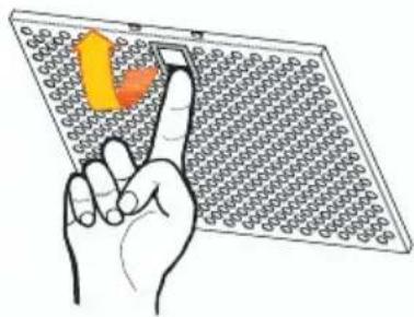
- Remove the Filters one at a time, supporting them with one hand while you pull the lever down with the other.
- Wash the Filters without bending them, and leave them to dry completely before replacing.
- Replace, taking care to ensure that the handle faces forwards.
natural_image
Illustration of a hand pointing at a grid-based device with a yellow arrow indicating direction (no text or symbols)Activated Charcoal Filter (Recirculation Version)
This cannot be washed or regenerated, and must be changed at least once every 4 months, or when led H starts to flash. The alarm signal only appears when the Suction motor is turned on.
Activating the alarm signal
- In Recirculation Version Hoods, the Filter Saturation Alarm must be activated on installation or at a later date.
- Turn the Lights and the Suction Motor off.
- Press button G.
- Within 5 seconds, press Button H until Led H flashes in confirmation:
- Led flashes twice – Activated Charcoal Filter saturation alarm ACTIVATED.
- Led flashes once – Activated Charcoal Filter saturation alarm DEACTIVATED.
Changing the Activated Charcoal Filter
Resetting the alarm signal
- Turn the Lights and the Suction Motor off.
- Press button H.
Changing the Filter
- Remove the Metal grease filters.
- Remove the saturated Activated Charcoal Filters, as indicated (A).
• Fit the new Filters, as indicated (B). - Replace the Metal grease filters.

Lighting
LIGHT REPLACEMENT
20 W halogen light.
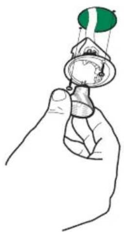
- Remove the 2 screws fixing the Lighting support, and pull it out of from the Hood.
• Extract the lamp from the Support. - Replace with another of the same type, making sure that the two pins are properly inserted in the lamp holder socket holes.
- Replace the Support, fixing it in place with the two screws removed as above.
natural_image
Hand holding a small object with a green flag on top, no text or symbols visiblenatural_image
Illustration of a chemical experiment setup with a conical flask, thermometer, and smokestack (no text or symbols)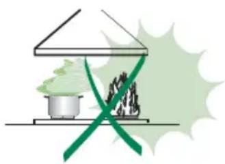
natural_image
Illustration of a greenhouse with a stove and a flame, crossed by a green ribbon (no text or symbols)natural_image
Diagram showing a mechanical component with a green arrow indicating direction, no text or symbols present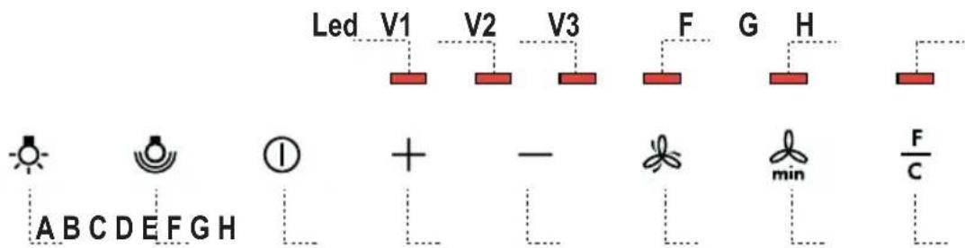
Bedieningspaneel
natural_image
Illustration of a hand pointing at a grid-based device with an arrow indicating rotation (no text or symbols)natural_image
Hand holding a pocket watch with a green flag above it (no text or symbols)natural_image
Illustration of a chemical experiment setup with a conical flask, thermometer, and smokestack (no text or symbols)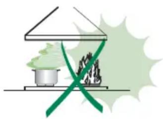
natural_image
Illustration of a greenhouse with a pot and smokestack emitting vapor, crossed by a green ribbon (no text or symbols)Componenti
natural_image
Diagram showing a mechanical component with a green arrow indicating direction, no text or symbols present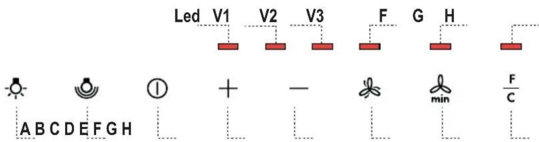
Quadro comandi
natural_image
Illustration of a hand pointing at a grid-based device with an arrow indicating rotation (no text or symbols)natural_image
Line drawing of a hand holding a pocket watch with a green flag above it (no text or symbols)natural_image
Illustration of a kitchen induction setup with a smokestack emitting vapor, a control panel, and a green X-shaped warning symbol (no text or labels)
natural_image
Illustration of a greenhouse with a pot and smokestack emitting vapor, crossed by a green ribbon (no text or symbols)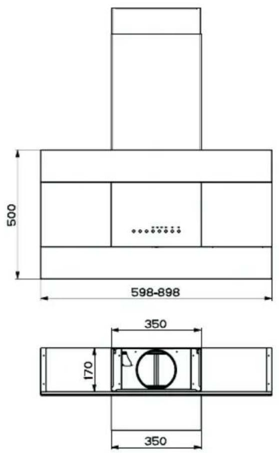
natural_image
Diagram showing a mechanical component with a green arrow indicating direction, no text or symbols present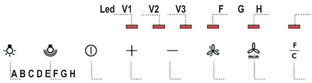
Kontrollpanel
natural_image
Illustration of a hand pointing at a grid-based device with a yellow arrow indicating direction (no text or symbols)natural_image
Illustration of a hand holding a globe with a pointer, no text or symbols presentnatural_image
Illustration of a chemical experiment setup with a conical flask, smoke, and a control panel (no text or symbols)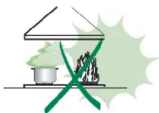
natural_image
Illustration of a greenhouse with a stove and smokestack emitting vapor, crossed by a green diagonal line (no text or symbols)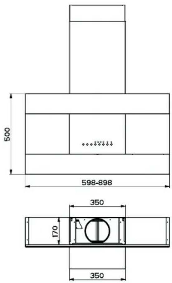
natural_image
Diagram showing a mechanical component with a green arrow indicating direction, no text or symbols present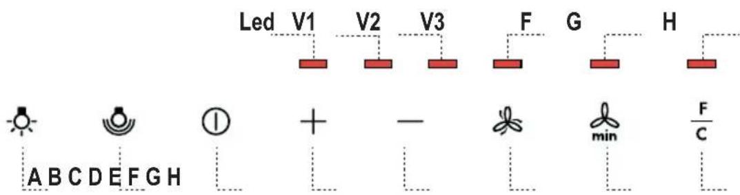
Kontrollpanel
natural_image
Illustration of a hand pointing at a grid-based device with an orange arrow indicating rotation (no text or symbols)natural_image
Illustration of a hand holding a globe with a green sphere above it (no text or symbols)natural_image
Illustration of a chemical experiment setup with a conical flask, thermometer, and smokestack (no text or symbols)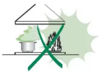
natural_image
Illustration of a greenhouse with a stove and smokestack emitting vapor, crossed by a green ribbon (no text or symbols)Ref. Stk. Installationsdele

AFSKÆRMET UDGAVE LUFTAFTRÆKSYSTEM
natural_image
Diagram showing a mechanical component with a green arrow indicating direction, no text or symbols present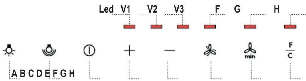
Betjeningspanel
natural_image
Illustration of a hand pointing at a grid-based device with an arrow indicating rotation (no text or symbols)Lugtfilter med aktivt kul (Filtrerende version)
natural_image
Illustration of a hand holding a globe with a pointer, no text or symbols presentnatural_image
Illustration of a chemical experiment setup with a conical flask, thermometer, and smokestack (no text or symbols)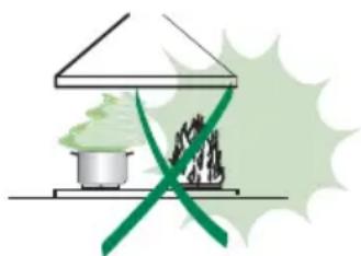
natural_image
Illustration of a greenhouse with a pot and two steam rising, crossed by a green ribbon (no text or symbols)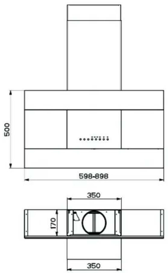
natural_image
Diagram showing a mechanical component with a green arrow indicating direction, no text or symbols present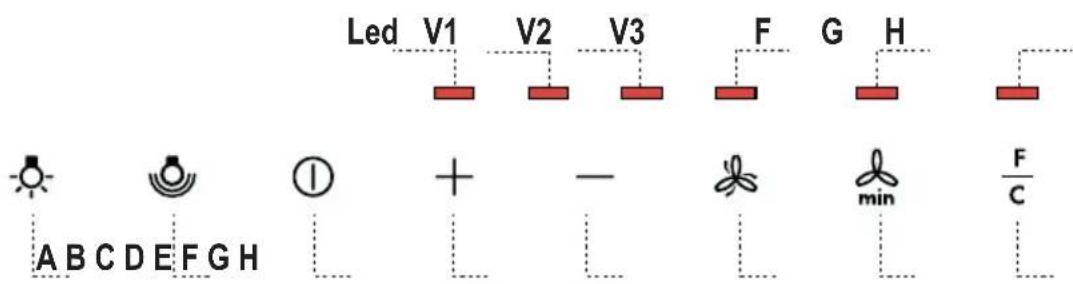
Käyttöpaneeli
natural_image
Illustration of a hand pointing at a grid-based device with a yellow arrow indicating direction (no text or symbols)natural_image
Illustration of a hand holding a globe with a green sphere above it (no text or symbols)If your appliance has a fault, please contact our service engineer and state the following numbers:
- INHALTSVERZEICHNIS
- DE
- INHOUDSOPGAVE
- NL
- INDICE
- IT
- INNEHÅLL
- SE
- INNHOLD
- NO
- INDHOLD
- DK
- SISÄLTÖ
- FI
- Anschlüss in abluftversion
- INSTALLATION
- USE
- MAINTENANCE
- Components
- Ref. Q.ty Product Components
- Ref. Q.ty Installation Components
- Q.ty Documentation
- Wall drilling and bracket fixing
- Mounting the hood body
- Connections
- DUCTED VERSION AIR EXHAUST SYSTEM
- RECYCLING VERSION AIR OUTLET
- Flue assembly
- Upper exhaust flue
- Lower exhaust flue
- ELECTRICAL CONNECTION
- Metal grease filters
- CLEANING THE SELF-BEARING METAL GREASE FILTERS
- Resetting the alarm signal
- Cleaning the Filters
- Activated Charcoal Filter (Recirculation Version)
- Activating the alarm signal
- Changing the Activated Charcoal Filter
- Changing the Filter
- Lighting
- LIGHT REPLACEMENT
- W halogen light.
- AFSKÆRMET UDGAVE LUFTAFTRÆKSYSTEM
- Lugtfilter med aktivt kul (Filtrerende version)
Brand : AEG-ELECTROLUX
Model : DD 9963
Category : Range hood