
ZHC9141 - Kitchen hood ZANUSSI - Free user manual and instructions
Find the device manual for free ZHC9141 ZANUSSI in PDF.
| Product type | Cooker hood |
| Brand | ZANUSSI |
| Model | ZHC9141 |
| Installation | Extracting (external evacuation) or recirculating (charcoal filter) |
| Minimum distance between hood and cooking surface | 650 mm |
| Power supply | 220-240 V ~ 50 Hz |
| Control type | Mechanical switches |
| Number of speeds | 3 |
| Lighting | Incandescent lamp 40 W |
| Grease filter | Metal, dishwasher safe or hand washable |
| Odor filter (optional) | Active charcoal, to be replaced every 2 months |
| Air outlet diameter | 150 mm (reduction to 120 mm possible with supplied adapter) |
| Electrical insulation class | Class II (no earth connection required) |
| Material | Steel (generally) |
| Metal filter maintenance | Every 2 months |
| Charcoal filter maintenance | Replace every 2 months, do not wash |
| External cleaning | Damp cloth with alcohol or mild detergent, no abrasives |
| Safety | Disconnect before maintenance; avoid flames under the hood |
| Included accessories | Clamps C (2), reduction adapter G, filter connector H (optional), charcoal filters L (optional) |
Frequently Asked Questions - ZHC9141 ZANUSSI
User questions about ZHC9141 ZANUSSI
0 question about this device. Answer the ones you know or ask your own.
Ask a new question about this device
Download the instructions for your Kitchen hood in PDF format for free! Find your manual ZHC9141 - ZANUSSI and take your electronic device back in hand. On this page are published all the documents necessary for the use of your device. ZHC9141 by ZANUSSI.
USER MANUAL ZHC9141 ZANUSSI
Instructions Manual INDEX
WARNING - COMPONENTS 8
INSTALLATION 9
USE - MAINTENANCE 10
3KCIJIYATAUJIA - TEXHINCHECKOE OBCJNYKUBAHNE 28
WARNING
This appliance has been designed for use as either an EXTRACTION (ducting to the outside) or RE-CIRCULATION (filtering) hood. The measurements contained on the drawings in this booklet refer to two models of cooker hood. Therefore, it is essential that you refer to the correct drawing when taking measurements for installation.
- The minimum distance between the cooking surface and the metal grease filters on the underside of the hood must be 650mm .
- This cooker hood must be installed in accordance with the installation instructions and all requirements must be adhered to.
- If the room where the cooker hood is to be used contains a fuel burning appliance such as a central heating boiler then its flue must be of the room sealed or balance flue type.
- If other types of flue or appliances are fitted ensure that there is an adequate supply of air to the room.
- When the range hood and appliance supplied with energy other than electricity are simultaneously in operation, the negative pressure in the room must not exceed 4 Pa (4x10⁻⁵ bar).
- Exhaust air may be discharged in accordance with official and statutory regulations only (e.g. national building regulations).
- The ducting system for this appliance must not be connected to any ventilation system which is being used for any other purpose.
- The ducting system for this appliance must not be connected to any existing ventilation system which is being used for any other purpose.
- Do not leave naked flames or carry out flambe cooking under this cooker hood.
- This appliance is not intended for use by persons (including children) with reduced physical, sensory or mental capabilities, or lack of experience and knowledge, unless they have been given supervision or instruction concerning use of the appliance by a person responsible for their safety.
- Children should be supervised to ensure that they do not play with the appliance
The symbol on the product or on its packaging indicates that this product may not be treated as household waste. Instead it shall be handed over to the applicable collection point for the recycling of electrical and electronic equipment. By ensuring this product is disposed of correctly, you will help prevent potential negative consequences for the environment and human health, which could otherwise be caused by inappropriate waste handling of this product. For more detailed information about recycling of this product, please contact your local city office, your household waste disposal service or the shop where you purchased the product.
CONNECTING THE POWER CABLE TO THE MAINS POWER SUPPLY
Before installation, check that the mains voltage indicated on the rating plate inside the appliance corresponds to the voltage available in your home. If the Hood is not fitted with a plug, fit the power cable with a plug of a type approved for the load indicated on the rating plate; when connecting directly to the mains, insert an omnipolar circuit breaker with a minimum contact aperture of 3mm and a size suitable for the load in question between the appliance and the mains supply, making sure it is of a type that complies with current regulations.
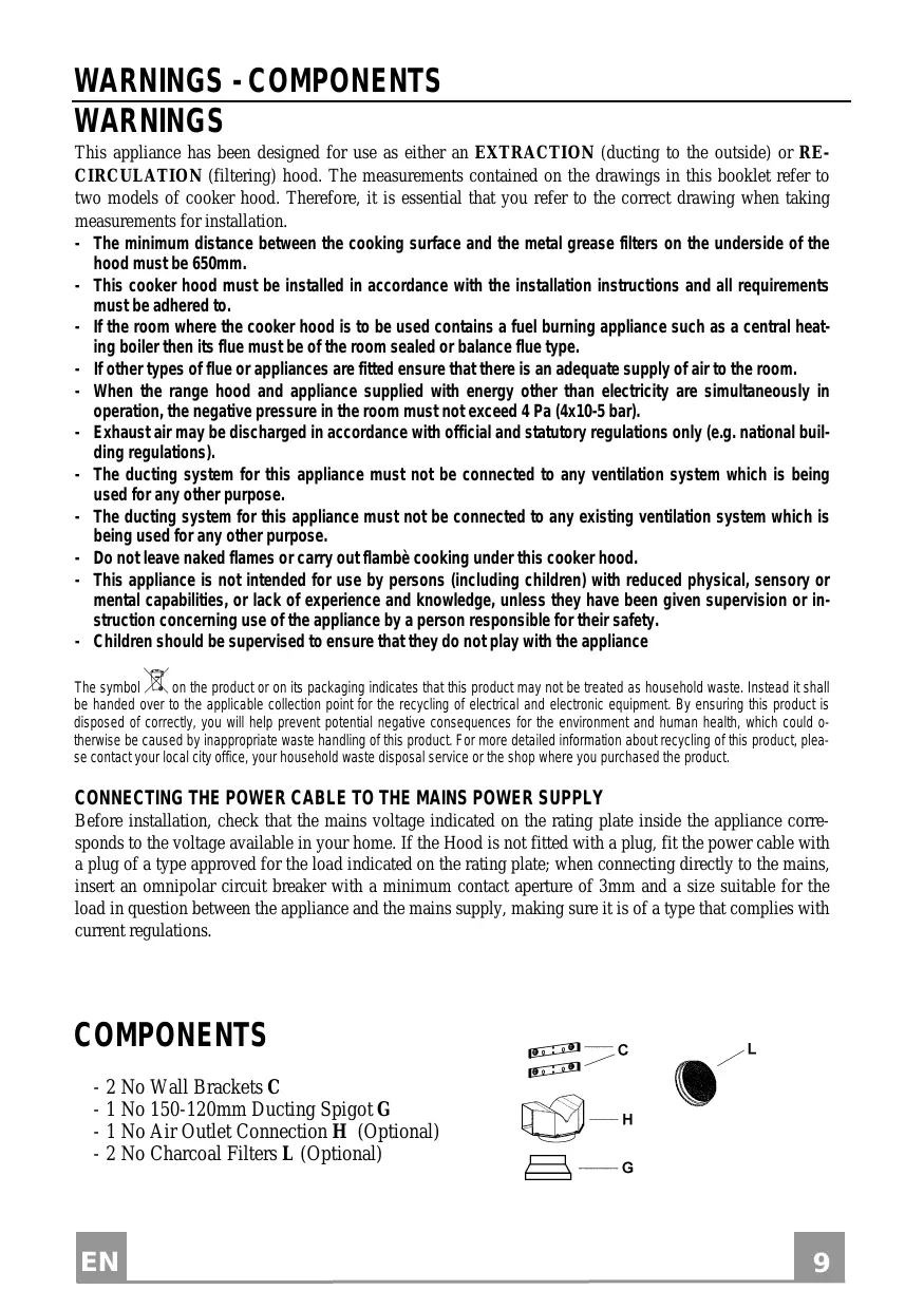
COMPONENTS
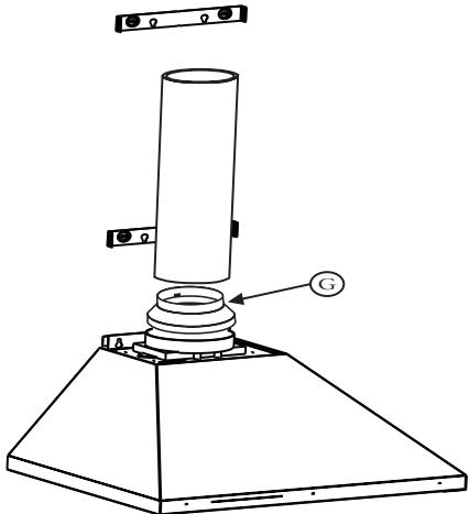
- 2 No Wall Brackets C
- 1 No 150-120mm Ducting Spigot G
- 1 No Air Outlet Connection H (Optional)
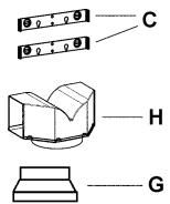
- 2 No Charcoal Filters L (Optional)
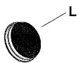
The cooker hood must be installed centrally over a cooking appliance. The minimum distance between the cooking surface and the metal grease filters on the underside of the hood must be at least 650mm .
To install the hood proceed as follows:
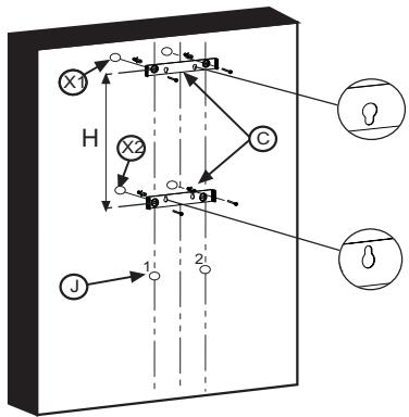
1) Drill six 8mm diameter holes at X1-X2-J and insert the plastic rawl plugs supplied as illustrated in fig. 2 ensuring the brackets are fitted as shown in the blow up.
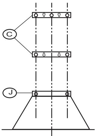
2) Secure the two brackets C to the wall inserting two of the screws supplied through the two holes on line X1-X2 as illustrated in fig. 2.
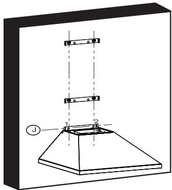
3) Slide the canopy down the wall to locate the key hole over the washer then secure the canopy to the wall by inserting two of the screws supplied through the two outer holes in the rim of the canopy J1 and J2 as illustrated in fig. 3.
4) EXTRACTION OR RECIRCULATION INSTALLATION:
- EXTRACTION (DUCTED)
When installing the ducted version, connect the hood to the chimney using either a flexible or rigid pipe 150 or 120mm , the choice of which is left to the installer.
- To install a 120 mm air exhaust connection,insert the reducer flange 9 on the hood body outlet.
Fix the pipe in position using sufficient pipe clamps (not supplied). - Remove any activated charcoal filters.
- RECIRCULATION (FILTERED)
- When the hood is fitted in the recirculation mode the Air Outlet Connection H should be fitted as illustrated in fig. 6.
- Fit the (optional) charcoal filters by repeating the following operation on each side of the motor housing. Place the two key hole slots in the filter L and turn the filter clockwise to lock the filter in position as illustrated in fig. 7.
WARNING: It is a possible fire hazard if the metal grease filters are not cleaned and the charcoal filters replaced regularly.
Fitting The Chimney
To fit the upper chimney A , place the top edge of the chimney over the bracket C as illustrated in fig. 8 and secure the chimney using two of the 2.9mm self tapping screws provided.
The distance H in the height between the fixing holes X1 and X2 is determined by the height of the upper chimney A .
To fit the lower chimney B , apply slight force to the two rear edges to increase the width of the aperture, then sleeve the chimney B over the chimney A as illustrated in fig. 9.
USE
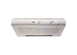
The cooker hood functions are controlled by a series of slider or push button switches mounted on the front of the hood and control the worktop lighting and fan motor speeds. This cooker hood will not remove steam.
1)SLIDER SWITCHES (fig.11):
- A switch controls the wotktop lighting - ON/OFF.
- A switch controls the fan speeds - OFF/ON-1-2-3.
- The red neon lamp illuminates when the motor is switched ON.
MAINTENANCE
N.B. Before carrying out any kind of maintenance, cleaning or replacing lamps, disconnect the hood from the mains supply.
- Lighting
40 W incandescent light (fig.10):
- Remove the metal grease filters.
- Unscrew the bulbs and replace them with new ones having the same characteristics.
-
Replace the metal grease filters.
-
Filters
ATTENTION- There could be a possible fire hazard if the filters are not replaced according to these instructions.
- The metal grease filter should be cleaned every two months or more frequently if the hood is used consistently and can be cleaned in a dishwasher or by hand using a mild detergent or liquid soap. When replacing, ensure that they are dry.
-
The charcoal filter cannot be washed and should be replaced at least every 2 months or more frequently if the hood is used consistently.
-
Cleaning
When cleaning the hood, it is recommended to use a damp cloth and mild liquid household cleaner. Never use abrasive cleaning materials.
ATTENTION: The manufacturer declines all responsibility for any damage or injury caused as a result of not following the instructions for installation, for maintenance and replacement times of filters indicated (in order to avoid a possible risk of fire when the filters are saturated with grease).
HINWEISE
UMLUFTBETRIEB (OPTION)
TEXHNUECKOE OBCJNYKUBAHNE
BHIMAHHE!IpeKJHe MeBbIIIOJIHrTbJIIO6Ie OIIepaIHHIO TeXo6cJIyKHBaHHIO,peMOHTy HJIIN 3aMeHe JAMIOueK, HeO6XoIHMo OTKJIIOuHTb IIpH6Op OT 3JIeKTPuYeCKoI cETH.
1.OcBeHHeHne
40 Br cBeta JIaMIIb HakaJIHbAHHa (pnc.10):
-ydaJIeHHe cMa3KN MeTaJIInueckNxΦJIbTpOB.
- OTBHHTHe JAMIOueK I 3aMeHHt b HX HOBbIMn, HMEIoIINx OJHaKOBbIe XapaKTePcHCTKNK.
- 3aMeHHTe cMa3Ka MeTaJIJIHuecKHX ΦJIbTpOB.
2. _Hbtpb
Heo6xoIIMO IOCTaTOUHO uactO (c yueToM peKHM aHIOJIb3OBAHnB bITgKKn), HO HepeKe pa3a B 2 MecHa, cHmAtb MeTaJIINuCeCKHe _IIIB TpbI H MbITb Hx B TeJIIOI MbJIbHO BoJe HIn Ke HeIOscpeIcTBHeHHo B IocyIDOMoeHoi MaIHHe. IocJIe 3TOrO _IIIB TpbI Heo6XoIIMO BBICHTb H yCTaHOBHTb Ha CBOE MeCtO (yTOJIbHbIE _IIIB TpbI HHKOrJa He MOOTc; Hx CJJeDyET MeHrTb KaKDbie 2 MecHa).
3. UNCTKA
IIJI YIcCTKN BHEIIHHX IOBepxHOCTeB BYITJAKKNIIOJIb3OBAtbcM MRAKOI TKAHBIO CO cINHPOM HJIN IpyTMMN IIOXIOIAIHM CpeIcTBAMN, IMeIOIIMNCB IIpoJaKe. He CJeIyET IIOJIb3OBAtbcA 6pa3NBHbIMN COCTaBMn.
BHIMAHHE! HaJIHne OTKpbIToro ORHn IpeIcTaBJIeT OIIaHcHOCTb IJIg HJIbTpOB, IIOTOMy He peKomeHdyETcOCTaBJIaTb TOpEJIky BKJIIOueHHo8 6e3 YcTaHOBJeHHoCBepxY IOcyIb. Heo6xoJIMO BblIOJIHaTb OIIepaUNI N IOUcTKe BblTJKKN I HJIBTpOB, a TaKke IepHOJInueckyo 3aMeHy IOcJIeIHHX, CJIeJy HAIIHM INHCTpyKUnm C TeM, YTO6bI H36eKaTb OIIaCHOCTH IOkapa.
BHIMAHHE! ΦHpMa-H3ROTOBHTeJIb He Hecet OTBETCTBEHHOCTH 3a BO3MOKHBIyIeP6, BO3HNKIIIN Bpe3yJIbTaTe HeIOCTaTOUHORO yXODa 3a JHKPOBBIM ΦHJbTpOM (MOHa KaKDbIE IBa MeCua), HeBbIIOJIHeHn 3aMeHbI yTOJIbHOro ΦHJbTpA H ECO6JIIODeHn OINCaHHbIX BbIiE HHCTpyKII IN MOHTaKy H IOKJIIOUeHnIO K JIeKTPHueCKo CETH.
1
2
3
4
5
| 6 | 7 |
| 8 | 9 |
| 10 | |
| 11 | |
www.electrolux.com

- Instructions Manual INDEX
- WARNING
- CONNECTING THE POWER CABLE TO THE MAINS POWER SUPPLY
- COMPONENTS
- - EXTRACTION (DUCTED)
- - RECIRCULATION (FILTERED)
- Fitting The Chimney
- USE
- MAINTENANCE
- HINWEISE
- UMLUFTBETRIEB (OPTION)
- TEXHNUECKOE OBCJNYKUBAHNE
- 1.OcBeHHeHne
- Br cBeta JIaMIIb HakaJIHbAHHa (pnc.10):
- _Hbtpb
- UNCTKA
Brand : ZANUSSI
Model : ZHC9141
Category : Kitchen hood