
ZH 1 - Uncategorized STIEBEL ELTRON - Free user manual and instructions
Find the device manual for free ZH 1 STIEBEL ELTRON in PDF.

| Product Type | Safety assembly for floor-mounted cylinders |
| Model | ZH 1 |
| Part Number | 074370 |
| Max Operating Pressure (factory set) | 0.6 MPa |
| Max Operating Pressure (with replacement cartridge) | 1.0 MPa |
| Water Connection | G 3/4 A male thread |
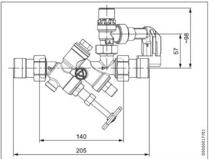
| Dimensions (H x W x D) | 205 mm x 140 mm x 57 mm |
| Pressure Reducing Valve (optional) | DMV/ZH 1, part no. 074371, outlet pressure range 0.15-0.60 MPa |
| Included Accessories | Replacement cartridge for diaphragm safety valve |
| Solder Fittings Set (optional) | For raising the safety valve |
| Safety Valve Type | Diaphragm safety valve, rotatable and replaceable |
| Pipe Break Prevention | Integrated into drain outlet |
| Drain Outlet | Telescopic with locking ring fitting, can be extended with 22 mm copper pipe |
| Installation Orientation | Angled or straight-through, horizontal or vertical (flow bottom to top) |
| Non-Return Valve | Check annually, replace if leaking |
| Maintenance Interval | Check safety valve every 6 months |
| Cleaning Method | Clean seat and gasket with damp cloth, no abrasives |
| Regulatory Certifications | ÖA certification for drinking water contact (Austria) |
| Intended Use | Protect electric floor-mounted cylinders and integral cylinders from excess pressure |
Frequently Asked Questions - ZH 1 STIEBEL ELTRON
User questions about ZH 1 STIEBEL ELTRON
0 question about this device. Answer the ones you know or ask your own.
Ask a new question about this device
Download the instructions for your Uncategorized in PDF format for free! Find your manual ZH 1 - STIEBEL ELTRON and take your electronic device back in hand. On this page are published all the documents necessary for the use of your device. ZH 1 by STIEBEL ELTRON.
USER MANUAL ZH 1 STIEBEL ELTRON
OBSŁUGA I INSTALACJA
USO E INSTALLAZIONE
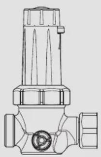
Sicherheitsgruppe | Bezpečnostní skupina | Predохранительный узел | Safety assembly | 安全组件 | Biztonsági részegység | Veiligheidsgroep | Grupa zabezpieczająca | Gruppo sicurezza
Druckminderventil | Tlakový redukční ventil | Редукционный клапан | Pressure reducing valve | 减压阀 | Nyomáscsökkentő szelep | Reduceerventiel | Zawór redukcyjny ciśnienia | Valvola riduttrice di pressione
» ZH 1
» DMV/ZH 1
natural_image
Technical line drawing of a valve component (no text or symbols)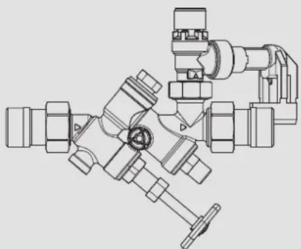
natural_image
Technical line drawing of a mechanical assembly with no visible text or symbolsBEDIENUNG
natural_image
Abstract geometric logo design with interlocking angular shapes (no text or symbols)R-15.2.4-21-17232
WIEN-ZERT
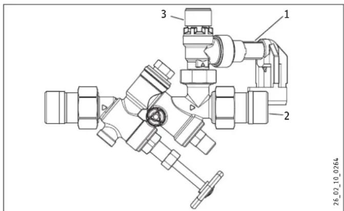
5.1.1 Montage in Eckform
26_02_10_0267
- General information 20
1.1 Document information 20
1.2 Symbols in this document 20
1.3 Units of measurement 20 - Safety 20
2.1 Intended use 20
2.2 Safety instructions 20
2.3 Product description 20
INSTALLATION
- Safety 21
3.1 General safety instructions 21
3.2 Instructions, standards and regulations 21 - Product description 21
4.1 Standard delivery 21
4.2 Special accessories 21 - Installation 21
5.1 Appliance installation 21 - Initial start-up 22
6.1 Adjusting the pressure reducing valve 22 - Maintenance 23
- Specification 24
8.1 Dimensions 24
8.2 Data tables 24
GUARANTEE
ENVIRONMENT AND RECYCLING
OPERATION
1. General information
1.1 Document information
The chapter "Operation" is intended for product users and qualified contractors.
The chapter "Installation" is intended for qualified contractors.

Read these instructions carefully before using the appliance and retain them for future reference.
Pass on the instructions to a new user if required.
1.2 Symbols in this document

Read the text next to this symbol carefully.
1.3 Units of measurement

All measurements are given in mm unless stated otherwise.
2. Safety
2.1 Intended use
The purpose of the appliance is to protect electric floor mounted cylinders and integral cylinders against excess pressure. If required, a pressure reducing valve available as a special accessory can supplement the safety assembly (see chapter "Product description / Special accessories").
2.2 Safety instructions

During the heat-up process, expansion water will drip from the safety valve.
If water continues to drip once heat-up is complete, please inform your qualified contractor.
2.3 Product description
The volume of water expands during heating. The expansion water must drip out via the safety valve and is routed away through the drain outlet.
INSTALLATION
3. Safety
Only a qualified contractor should carry out installation, commissioning, maintenance and repair of the appliance.
3.1 General safety instructions
We guarantee trouble-free functional and operational reliability only if original accessories and spare parts intended for the appliance are used.
3.2 Instructions, standards and regulations

Observe all applicable national and regional regulations and instructions.
ÜA certification for building products in contact with drinking water in Austria:
4. Product description
A pipe break is integrated into the drain outlet of the safety valve, which prevents the waste water being sucked back.
The drain outlet is fitted on the safety valve with a locking ring fitting. It is rotatable and fits into any installation situation thanks to its telescopic extension. The drain outlet can also be extended with a copper pipe and a locking ring fitting.
The diaphragm safety valve can be rotated, repositioned and replaced at the threaded fitting for different methods of installation.
4.1 Standard delivery
The following are delivered with the appliance:
- Replacement cartridge for diaphragm safety valve
4.2 Special accessories
4.2.1 Pressure reducing valve DMV/ZH 1
Special pressure reducing valve to supplement the appliance if the supply pressure at the installation location is greater than 0.48 MPa.
4.2.2 Solder fittings set
For raising the safety valve
5. Installation
5.1 Appliance installation

Note
No shut-off valves, restrictions or strainers must be installed between the safety valve and the floor mounted cylinder.
▶ Please note that, depending on the supply pressure, you may also need a pressure reducing valve (see chapter "Product description / Special accessories").
▶ The drain connection of the safety valve must remain open to the atmosphere.
▶ Flush all pipework thoroughly before installation.
▶ Install the appliance in the cold water inlet. The appliance is suitable for angled or straight-through installation in horizontal and vertical pipework. Please note that the appliance should only be installed in vertical pipework if the flow direction goes from bottom to top.
5.1.1 Angled installation
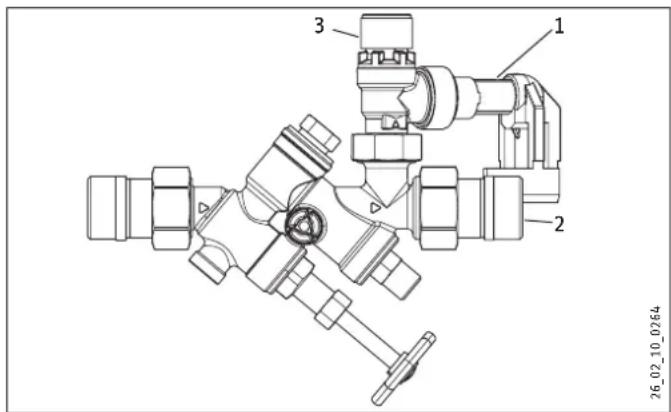
1 Drain outlet
2 DHW outlet
3 Diaphragm safety valve
▶ Slacken off the nut on the safety valve.
▶ Remove the safety valve with the fitting. Interchange it with the output fitting.
▶ Tighten the safety valve fitting.
Even when secured in place, the safety valve can still be rotated.
5.1.2 Drain outlet extension
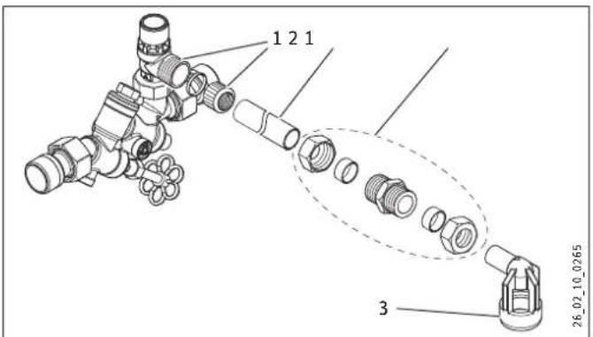
1 Locking ring fitting
2 Copper pipe 22 mm (not part of the standard delivery)
3 Drain outlet
5.1.3 Raising the safety valve
To make maintenance work easier, the appliance can be installed above the floor mounted cylinder. For this, you will need the solder fittings set, which is available as a special accessory.
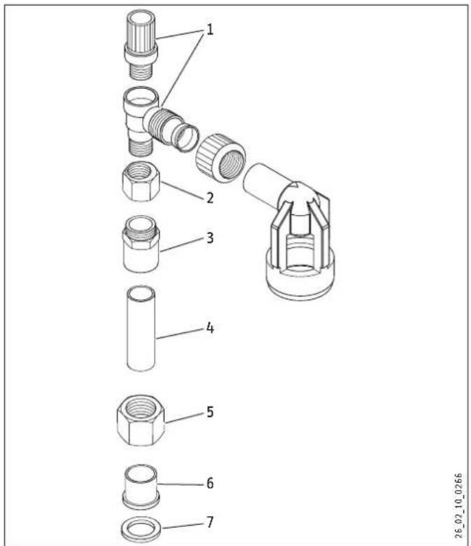
1 Safety valve
2 Eccentric fitting
3 Twin nipple
4 Copper pipe
5 Union nut
6 Solder grommet
7 Sealing washer
▶ Solder a copper pipe into the solder grommet.
▶ Position the union nut with centric hole over the copper pipe.
▶ Solder the twin nipple onto the other end of the copper pipe.
▶ Install the safety valve with the eccentric fitting onto the twin nipple. Tighten the eccentric fitting. The safety valve can also be rotated when the fitting has been tightened.
▶ Fit the complete unit onto the safety assembly. Ensure that the sealing washer is seated correctly. Tighten the fitting.
6. Initial start-up
▶ Check the safety valve and the non-return valve (see chapter "Maintenance").
6.1 Adjusting the pressure reducing valve
For setting range, see chapter "Specification / Data table".
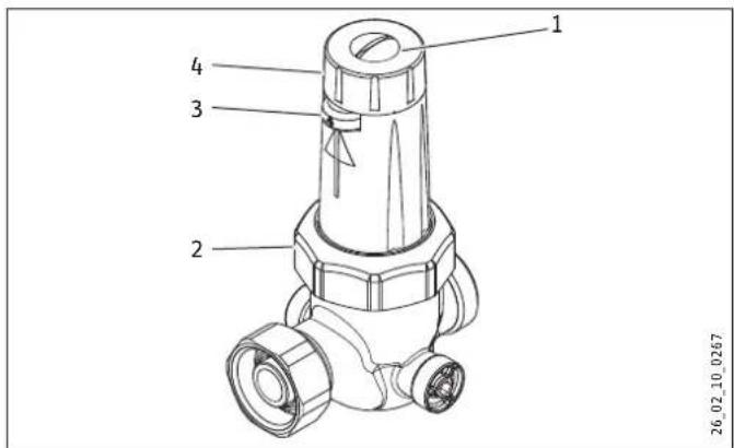
1 Locking screw
2 Union nut
3 Outlet pressure display
4 Setting dial
▶ Slacken off the locking screw on the dial.
▶ Turn the setting dial towards the minus to reduce the pressure or towards the plus to increase it.
The pressure reducing valve can also be rotated during operation so that the outlet pressure display is visible.
7. Maintenance
For later maintenance work on the installation, you can shut off the supply line to the safety assembly.
Depending on the position of the safety valve, you may need to drain the floor mounted cylinder before any maintenance work.
Seat and gasket of the diaphragm safety valve can be cleaned without changing the response pressure.
7.1.1 Checking, cleaning and replacing the safety valve
▶ Check the safety valve every six months.
▶ Ensure that a suitable collection container is available, as water will escape when the safety valve is vented. Turn the vent cap two or three times anti-clockwise.
During heat-up, expansion water must drip into the tundish.
▶ Check the function of the non-return valve if no water emerges.
Water should no longer drip out once heat-up is complete.
▶ If water continues to escape after heat-up, check the safety valve for dirt. Once you have unscrewed the upper section, you can clean the seat and gasket of the safety valve without changing the response pressure. A damp cloth is sufficient for this. Never use abrasive or corrosive cleaning agents.
▶ Check the supply pressure. If 0.5 MPa is exceeded, insert a pressure reducing valve.
▶ If necessary, check the function of the pressure reducing valve.
If a repair is required, you can replace the complete safety valve.
7.1.2 Cleaning the pressure reducing valve
▶ Slacken off the union nut on the spring cap.
▶ Remove the pressure reducing valve with the spring cap from the casing.
▶ Clean the pressure reducing valve with clear, cold water.
7.1.3 Checking the non-return valve
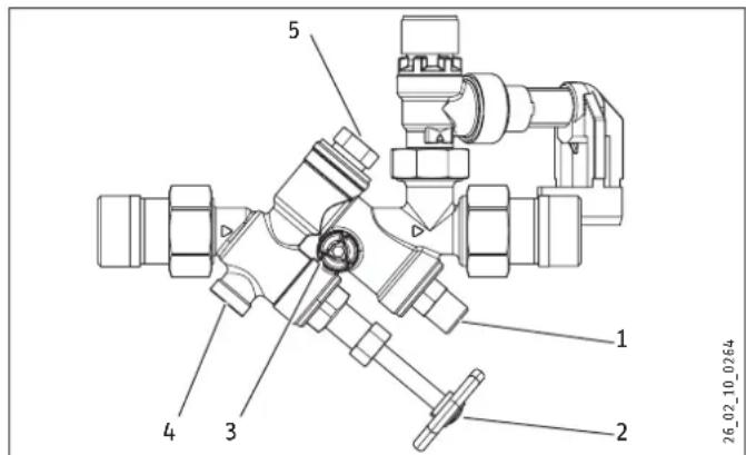
1 Service valve for non-return valve (2nd shut-off valve)
2 Shut-off valve
3 Pressure gauge connection
4 Service plug for non-return valve
5 Non-return valve
▶ Check the non-return valve annually.
▶ Close the shut-off valve using the handwheel.
▶ Unscrew and remove the service plug for the non-return valve.
If water continues to be discharged, the non-return valve is leaking:
▶ Close the second shut-off valve.
▶ Replace the non-return valve.
8. Specification
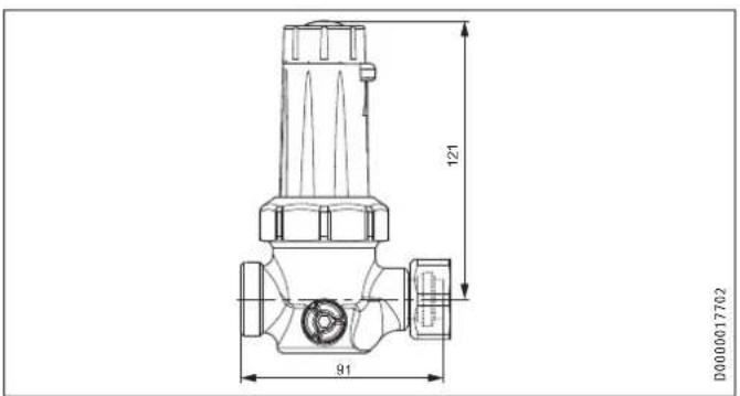
8.1 Dimensions
Pressure reducing valve
8.2 Data tables
| Safety assembly | ||
| Type ZH 1 | ||
| Part number 074370 | ||
| Operating data | ||
| Can be used for appliances with maximum operating pressure | ||
| Factory-set | MPa | 0,6 |
| With replacement cartridge | MPa | 1,0 |
| Water connection (male thread) G 34 A | ||
| Pressure reducing valve | ||
| Type DMV/ZH 1 | ||
| Part number 074371 | ||
| Operating data | ||
| Can be used for appliances with maximum operating pressure | MPa | 0,6 |
| Outlet pressure | ||
| Factory-set | MPa | 0,40 |
| Minimum | MPa | 0,15 |
| Maximum | MPa | 0,60 |
| Water connection (male thread) G 34 A | ||
Guarantee
The guarantee conditions of our German companies do not apply to appliances acquired outside of Germany. In countries where our subsidiaries sell our products a guarantee can only be issued by those subsidiaries. Such guarantee is only granted if the subsidiary has issued its own terms of guarantee. No other guarantee will be granted.
We shall not provide any guarantee for appliances acquired in countries where we have no subsidiary to sell our products. This will not affect warranties issued by any importers.
Environment and recycling
▶ Dispose of the appliances and materials after use in accordance with national regulations.

▶ If a crossed-out waste bin is pictured on the appliance, take the appliance to your local waste and recycling centre or nearest retail take-back point for reuse and recycling.
This document is made of recyclable paper.
- Dispose of the document at the end of the appliance's life cycle in accordance with national regulations.
操作
natural_image
Abstract geometric logo design with interlocking angular shapes (no text or symbols)R-15.2.4-21-17232
WIEN-ZERT
4. Termékleírás
natural_image
Abstract geometric logo design with interlocking angular shapes (no text or symbols)R-15.2.4-21-17232
WIEN-ZERT
natural_image
Abstract geometric logo design with interlocking angular shapes (no text or symbols)R-15.2.4-21-17232
WIEN-ZERT
4. Opis produktu
natural_image
Abstract geometric logo design with interlocking angular shapes (no text or symbols)R-15.2.4-21-17232
WIEN-ZERT
- BEDIENUNG
- INSTALLATION
- GUARANTEE
- ENVIRONMENT AND RECYCLING
- OPERATION
- General information
- Document information
- Symbols in this document
- Units of measurement
- Safety
- Intended use
- Safety instructions
- Product description
- Safety
- General safety instructions
- Instructions, standards and regulations
- Product description
- Standard delivery
- Special accessories
- Pressure reducing valve DMV/ZH 1
- Solder fittings set
- Installation
- Appliance installation
- Note
- Angled installation
- Drain outlet extension
- Raising the safety valve
- Initial start-up
- Adjusting the pressure reducing valve
- Maintenance
- Checking, cleaning and replacing the safety valve
- Cleaning the pressure reducing valve
- Specification
- 操作
- Termékleírás
- WIEN-ZERT
- Opis produktu
Brand : STIEBEL ELTRON
Model : ZH 1
Category : Uncategorized