23Z012 - Air-conditioner Zelmer - Free user manual and instructions
Find the device manual for free 23Z012 Zelmer in PDF.

| Product Type | Portable Air Conditioner |
| Brand | Zelmer |
| Model | 23Z012 |
| Cooling Capacity | 9000 BTU/h |
| Power Supply | 220-240 V ~ 50 Hz |
| Power Consumption (Cooling) | 1000 W |
| Airflow Rate | 350 m³/h |
| Noise Level | ≤ 65 dB(A) |
| Refrigerant Type | R-410A |
| Dimensions (W x D x H) | 450 x 350 x 700 mm |
| Net Weight | 25 kg |
| Functions | Cooling, Fan, Dehumidification, Sleep Mode |
| Timer | 24-hour timer |
| Remote Control | Yes |
| Filter Type | Washable mesh filter |
| Installation | Window exhaust kit included |
| Energy Efficiency Class | A |
| Water Drainage | Automatic evaporation or manual drain |
Frequently Asked Questions - 23Z012 Zelmer
User questions about 23Z012 Zelmer
0 question about this device. Answer the ones you know or ask your own.
Ask a new question about this device
Download the instructions for your Air-conditioner in PDF format for free! Find your manual 23Z012 - Zelmer and take your electronic device back in hand. On this page are published all the documents necessary for the use of your device. 23Z012 by Zelmer.
USER MANUAL 23Z012 Zelmer
natural_image
White industrial air conditioner unit with ventilation slots and a 'zelmer' brand logo (no text-heavy elements)PL
2-8
Instructions for use Portable air conditioner Type 23Z012
Spis treści
Uwagi wstępne 2
natural_image
Diagram of a portable air conditioner unit connected to a coiled hose with a cross symbol (no text or labels)natural_image
Diagram of a door with double-headed arrows indicating direction, no text or symbols present
natural_image
Simple line drawing of a device connected to a wall-mounted panel (no text or symbols)PANEL STEROWANIA

flowchart
graph TD
    A["A"] --> Timer
    Timer --> SWING
    SWING --> FAN SPEED
    FAN SPEED --> ON/OFF
    ON/OFF --> TEMP+
    TEMP+ --> TEMP-
    TEMP- --> H
    MODE["MODE"] --> C
    C --> B["B"]
    B --> D["D"]
    E["E"] --> F["F"]
    F --> G["G"]
    G --> H["H"]
FUNKCJE KLIMATYZATORA
natural_image
Diagram of a portable air conditioner unit connected to a curved duct with a cross symbol (no text or labels)natural_image
Diagram showing two arrows pointing outward from a rectangular panel or door, with no text or symbols present.
natural_image
Simple line drawing of a device connected to a wall-mounted panel (no text or symbols)OVLÁDACÍ PANEL

flowchart
graph TD
    A["A"] --> Timer
    Timer --> Swing
    Swing --> FanSpeed["FAN SPEED"]
    FanSpeed --> ON/OFF["ON/OFF"]
    ON/OFF --> Temp+
    Temp+ --> TEMP-
    Temp- --> H["H"]
    B["B"] --> TIME
    TIME --> MODE
    MODE --> C["C"]
    C["C"] --> D["D"]
    D["D"] --> E["E"]
    E["E"] --> F["F"]
    F["F"] --> G["G"]
    G["G"] --> Temp+
    Temp+ --> ON/OFF
    ON/OFF --> PowerWaterFull["POWER WATER FULL"]
    PowerWaterFull --> TIME
    TIME --> TIME_P
    TIME_P --> TIME_H
    TIME_H --> MODE
PRAVIDELNÉ PROHLÍDKY PŘÍSTROJE
natural_image
Diagram of a portable air conditioner unit connected to a coiled hose with a cross symbol (no text or labels)OVLÁDACÍ PANEL
flowchart
graph TD
    A["A"] --> Timer
    Timer --> SWING
    SWING --> FAN SPEED
    FAN SPEED --> ON/OFF
    ON/OFF --> G
    G --> TEMP+
    TEMP+ --> TEMP-
    TEMP- --> H
    style Timer fill:#f9f,stroke:#333
    style SWING fill:#ccf,stroke:#333
    style FAN SPEED fill:#cfc,stroke:#333
    style ON/OFF fill:#fcc,stroke:#333
    style G fill:#cff,stroke:#333
    style TEMP- fill:#ffc,stroke:#333
    style TEMP+ fill:#cfc,stroke:#333
    style MODE fill:#fcc,stroke:#333
    style_B["B"] --> TIME
    B --> SET/RESET
    B --> NET/RESET
    C["C"] --> TIME
    C --> NET/RESET
    D["D"] --> MODE
    E["E"] --> TIME
    E --> ON/OFF
    F["F"] --> TIME
    F --> ON/OFF
    G["G"] --> TIME
    G --> ON/OFF
LCD DISPLEJ
natural_image
Diagram of a portable air conditioner unit connected to a coiled hose with a black X symbol (no text or labels)natural_image
Simple line drawing of a device with two downward arrows and an internal bidirectional arrow (no text or symbols)natural_image
Simple line drawing of a device with a mounted device and a wall-mounted panel (no text or symbols)Függöleges ablak
natural_image
Diagram of a door with double-headed arrows indicating direction, no text or symbols present
natural_image
Simple line drawing of a device connected to a wall-mounted panel (no text or symbols)KEZELÓPANEL

flowchart
graph TD
    A["A"] --> Timer
    Timer --> SWING
    SWING --> FAN SPEED
    FAN SPEED --> ON/OFF
    ON/OFF --> G
    G --> TEMP+
    TEMP+ --> H
    H --> MODE
    MODE --> C
    C --> B["B"]
    B --> A
    style Timer fill:#f9f,stroke:#333
    style SWING fill:#ccf,stroke:#333
    style FAN SPEED fill:#cfc,stroke:#333
    style ON/OFF fill:#fcc,stroke:#333
    style TEMP+ fill:#ffc,stroke:#333
    style H fill:#cff,stroke:#333
LCD KIJELZÖ
natural_image
Diagram of a portable air conditioner unit connected to a coiled hose with a black X symbol (no text or labels)natural_image
Simple line drawing of a container with two downward arrows and an internal double-headed arrow (no text or symbols)natural_image
Simple line drawing of a door handle with a mounted device (no text or symbols)Fereastră verticală

natural_image
Diagram showing two arrows pointing outward from a rectangular panel or door, with no text or symbols present.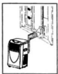
natural_image
Simple line drawing of a device connected to a wall-mounted panel (no text or symbols)natural_image
Technical line drawing of a mechanical assembly with mounting holes and a central component (no text or symbols)Instalarea tevilor de evacuare a apei
natural_image
Technical line drawing of a portable air conditioner unit with ventilation grilles and a coiled hose (no text or symbols)CARACTERISTICILE APARATULUI
PANOU DE COMANDĂ

flowchart
graph TD
    A["A"] --> Timer
    Timer --> SWING
    SWING --> FAN SPEED
    FAN SPEED --> ON/OFF
    ON/OFF --> TEMP+
    TEMP+ --> TEMP-
    TEMP- --> H["H"]
    style Timer fill:#f9f,stroke:#333
    style SWING fill:#ccf,stroke:#333
    style FAN SPEED fill:#cfc,stroke:#333
    style ON/OFF fill:#fcc,stroke:#333
    style TEMP+ fill:#ffc,stroke:#333
    style TEMP- fill:#fcc,stroke:#333
    style H fill:#fff,stroke:#333
natural_image
Diagram of a portable air conditioner unit connected to a coiled hose with a black X symbol (no text or labels)natural_image
Simple line drawing of a container with two downward arrows and an internal arrow, no text or symbols present.natural_image
Simple line drawing of a device with a handle and control panel (no text or symbols)Вертикальное окно

natural_image
Diagram of a door with directional arrows indicating movement, no text or symbols present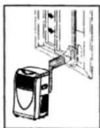
natural_image
Simple line drawing of a washing machine with a handle, no text or symbols presentnatural_image
Line drawing of a portable air conditioner unit with ventilation grilles and a coiled tube (no text or symbols)ПАНЕЛЬ УПРАВЛЕНИЯ
flowchart
graph TD
    A["A"] --> Timer
    Timer --> SWING
    SWING --> FAN SPEED
    FAN SPEED --> ON/OFF
    ON/OFF --> TEMP+
    TEMP+ --> TEMP-
    TEMP- --> H["H"]
    style Timer fill:#f9f,stroke:#333
    style SWING fill:#ccf,stroke:#333
    style FAN SPEED fill:#cfc,stroke:#333
    style ON/OFF fill:#fcc,stroke:#333
    style TEMP+ fill:#ffc,stroke:#333
    style TEMP- fill:#fcc,stroke:#333
    style H fill:#fff,stroke:#333
natural_image
Diagram of a portable air conditioner unit connected to a curved duct with a black X symbol (no text or labels)natural_image
Simple line drawing of a device with two downward arrows and an internal bidirectional arrow (no text or symbols)natural_image
Simple line drawing of a device with a bracket and a sensor, no text or symbols presentВертикален прозорец

natural_image
Diagram showing two arrows pointing outward from a rectangular frame, with a vertical double-headed arrow indicating width (no text or symbols present)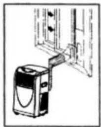
natural_image
Simple line drawing of a washing machine with a door and window (no text or symbols)natural_image
Line drawing of a portable air conditioner unit with ventilation grilles and a coiled hose (no text or symbols)ХАРАКТЕРИСТИКА НА УРЕДА
КОНТРОЛЕН ПАНЕЛ

flowchart
graph TD
    A["A"] --> Timer
    Timer --> SWING
    SWING --> FAN SPEED
    FAN SPEED --> ON/OFF
    ON/OFF --> TEMP+
    TEMP+ --> TEMP-
    TEMP- --> H["H"]
    style Timer fill:#f9f,stroke:#333
    style SWING fill:#ccf,stroke:#333
    style FAN SPEED fill:#cfc,stroke:#333
    style ON/OFF fill:#fcc,stroke:#333
    style TEMP+ fill:#ffc,stroke:#333
    style TEMP- fill:#cfc,stroke:#333
    style H fill:#fcc,stroke:#333
natural_image
Diagram of a portable air conditioner unit connected to a coiled hose with a black X symbol (no text or labels)natural_image
Simple line drawing of a device with two downward arrows and an internal arrow, no text or symbols present.natural_image
Simple line drawing of a door handle and adjacent device (no text or symbols)Вертикальне вікно
natural_image
Diagram of a door with double-headed arrows indicating direction, no text or symbols present
natural_image
Simple line drawing of a washing machine connected to a wall-mounted device (no text or symbols)ПАНЕЛЬ УПРАВЛІННЯ

flowchart
graph TD
    A["A"] --> Timer
    Timer --> SWING
    SWING --> FAN SPEED
    FAN SPEED --> ON/OFF
    ON/OFF --> G
    G --> TEMP+
    TEMP+ --> H
    H --> MODE
    MODE --> C
    C --> B["B"]
    B --> A
    style Timer fill:#f9f,stroke:#333
    style SWING fill:#ccf,stroke:#333
    style FAN SPEED fill:#cfc,stroke:#333
    style ON/OFF fill:#fcc,stroke:#333
    style TEMP+ fill:#ffc,stroke:#333
    style H fill:#cff,stroke:#333
LCD - ДИСПЛЕЙ
Safety instructions 58
Technical parameters 59
Installation 59
Appliance features....61
Names of parts 61
Control panel 61
LCD display 61
Remote controller 62
Air conditioner functions 62
Automatic switch on/ switch off using the control panel 63
Automatic switch on / switch off using the remote controller....63
Water drainage methods....63
Cleaning and maintenance 63
Before the start of the season 64
Before the end of the season 64
Troubleshooting 64
Periodic inspection of the appliance....64
Ecology – Environmental protection....64
Dear Customers!
Please read this instruction manual carefully. Pay special attention to important safety instructions in order to prevent accidents and/or avoid damage to the appliance. Keep this instruction manual for future reference.
INTRODUCTION
- A portable air conditioner is an expensive appliance, therefore it is recommended that the appliance is installed by an experienced installer. Otherwise not only material damage may occur, but the air conditioner may also function improperly and its efficiency may be decreased.
– Zelmer S.A. shall not be held liable for failures of air conditioners that have not been properly installed.
SAFETY INSTRUCTIONS
- Please read the whole instruction manual before operating the air conditioner.
- Plug the air conditioner only to a grounded AC electrical outlet with a voltage in accordance with the voltage provided on the rating label.
Always place the appliance on a flat, even surface.
Unplug the air conditioner when not in use and before cleaning. -
- Do not unplug by pulling on cord.
– Never operate the air conditioner if it has a damaged cord or if the housing of the heating assembly is visibly damaged.
If the supply cord is damaged, it must be replaced by a qualified service agent in order to avoid a hazard.
The appliance can only be repaired by qualified service personnel. Improper servicing may cause a serious hazard to the user. In case of defects please contact an authorized service center.
Do not use the appliance in the following locations: -
- next to a source of water or in an area where the appliance may have direct contact with water,
• in an area where oil is likely to splash,
• in an area exposed to direct sunlight, - in the greenhouse.
– Never insert your fingers or any foreign objects into the air outlet. Take special care to warn children of these dangers.
– Always store the unit upright in order to maintain the compressor in a proper condition.
– There is a risk of overheat if the appliance is covered. Never block the ventilation openings during operation.
- Do not use abrasive detergents such as emulsions, cream cleaners, polishes, etc. to clean the heating assembly housing. They may remove the graphic information symbols such as: as scales, marks, warning signs etc.
- This appliance is not intended for use by persons (including children) with reduced physical, sensory or mental capabilities, or lack of experience and knowledge, unless they have been given supervision or instruction concerning use of the appliance by a person responsible for their safety.
– Children should be supervised to ensure that they do not play with the appliance.
Instructions concerning the remote controller
- Be sure there are no objects between the remote controller and the receiver of the unit. Otherwise the air conditioner will not operate.
- Keep the remote controller away from all liquids.
- Protect the remote controller from high temperatures and exposure to radiation.
- Keep the remote controller away from electromagnetic interference supplied by other household appliances.
Make sure the above instructions have been understood.
TECHNICAL PARAMETERS
The technical parameters are indicated on the rating label.
The air conditioner is a class I appliance equipped with a cord with a grounding wire and a grounding plug.
The air conditioner fulfills the requirements of the existing norms.
The appliance is in conformity with the requirements of the directives:
Low voltage appliance (LVD) - 2006/95/EC
Electromagnetic compatibility (EMC) - 2004/108/EC. -
The appliance was marked by the CE sign on the rating label.
INSTALLATION
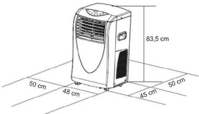
The selection of the location
Install the air conditioner on a plat surface where the air outlets will not be covered. A minimum clearance of 50 cm from a wall or other obstacles should be kept.
Installation accessories
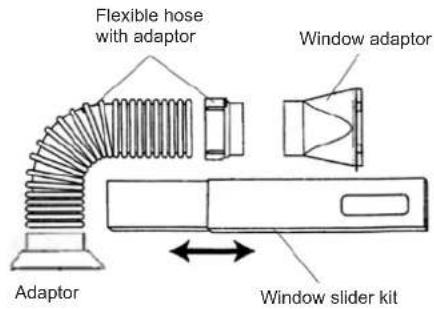
Flexible hose with adaptor 1 set, 3 elements
Hose length from 50 cm to 200 cm
Window adaptor set 1 element
Window slider kit 1 set, 2 elements
Dimensions from 67.5 cm to 123 cm 1 set, 1 element
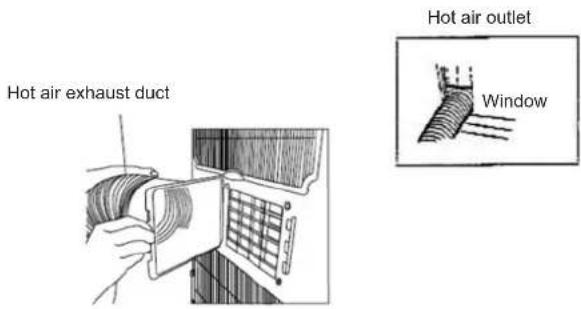
Air exhaust duct installation
- Attach the square adaptor of the air exhaust hose to the hot air outlet grill.
- Put the other end of the duct /outlet/ to a nearby window or other place which allows the air to escape the room.
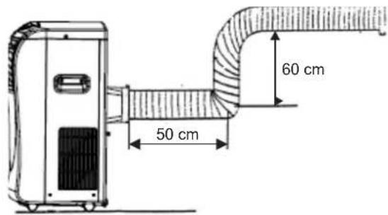
NOTICE: The duct can be compressed or extended between 60 cm and 180 cm. It is recommended to keep the duct length to a minimum.
Keep the duct in a horizontal position during installation, do not extend the duct or attach other air outlets. Failure risk.
Duct installation instruction
Reattach the air exhaust duct if it is not tight. Twist off the adaptor with three full turns and then screw the adaptor on as shown in the picture below.
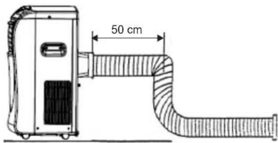
Properly installed ducts are shown in the picture below (if you install the ducts onto a wall, the height of the installation should be between 40 and 130 cm).
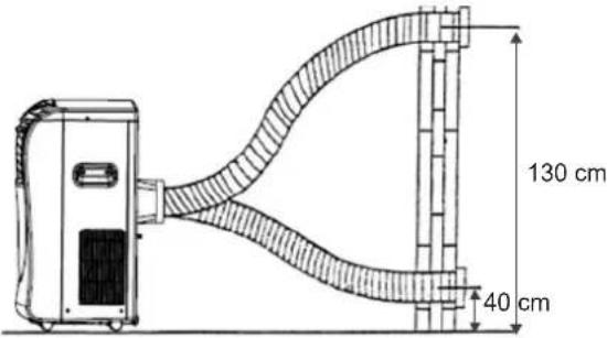
If the duct needs to be bent, please follow the instructions in the pictures below during installation.
An example of an improperly installed duct. This may cause failure of the air conditioner or its improper functioning.
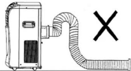
natural_image
Diagram of a portable air conditioner unit connected to a coiled hose with a black X symbol (no text or labels)Window installation kit
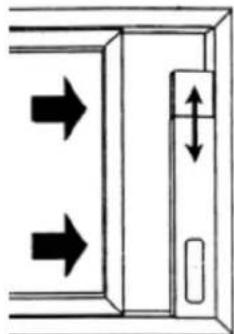
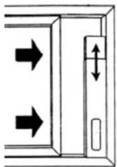
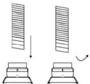
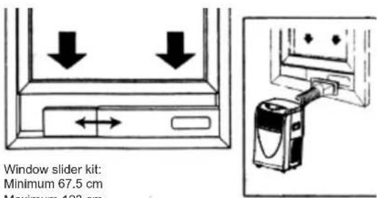
The air conditioner set is equipped with a window slider designed to fit "vertical" or "horizontal" window applications. It facilitates the installation of air inlet/outlet ducts. However, it may be necessary to modify some aspects of the installation procedure for certain types of windows. Please follow the instructions in the pictures below concerning the minimum and maximum window openings.
Horizontal window
Vertical window
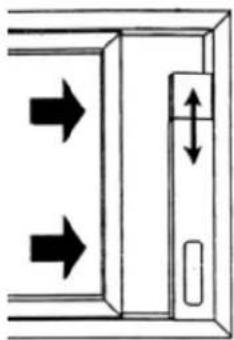
natural_image
Diagram showing two arrows pointing outward from a rectangular structure with a vertical double-headed arrow indicating width (no text or symbols)
natural_image
Simple line drawing of a device connected to a wall-mounted panel (no text or symbols)Window slider kit:
Minimum 67.5 cm
Maximum 123 cm
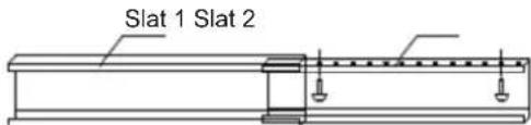
Attach the window slider to the slat using two screws (see picture below).
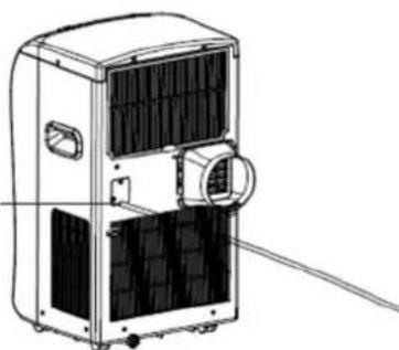
The installation of the water drainage hose
Install the water drainage hose in the opening on the back of the appliance. Make sure the drainage hose is correctly positioned in order to avoid the improper functioning of the eclectic control (see picture below).
Water drainage opening
natural_image
Technical line drawing of a portable air conditioner unit with ventilation grilles and a coiled hose (no text or symbols)APPLIANCE FEATURES
The portable air conditioner enables to maintain the desired temperature and to lower the air humidity. Thanks to its flexible features it can be used on various occasions and in various rooms. Its multiple functions include to cooling, dehumidifying, fanning ventilation and heating. This model has been specially designed for household or office use.
It is recommended to use the air conditioner in rooms with the temperature ranging between 17°C and 35°C.
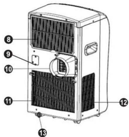
NAMES OF PARTS
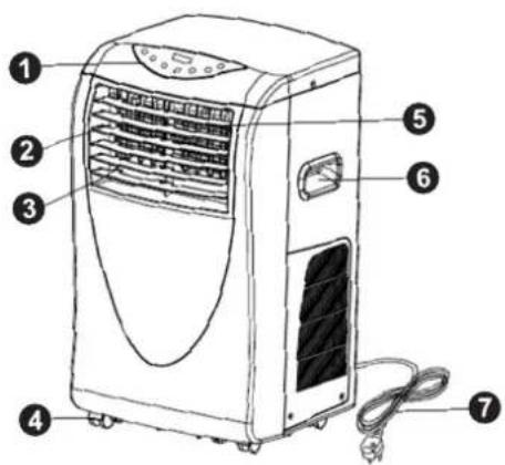
- Control panel with display.
- Left/right swinging fins (automatically adjusted).
- Ventilation opening.
- Caster.
- Upper/lower swinging fins (manually adjusted).
- Carrying handle.
- Supply cord with plug.
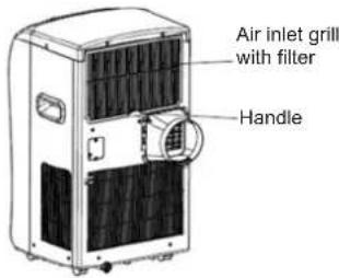
- Upper air inlet grill with filter.
- Water drainage hose opening.
- Air outlet.
- Lower air inlet grill.
- Side air inlet grill.
- Water release stopper.
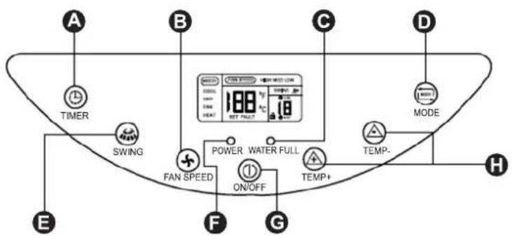
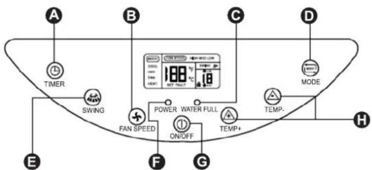
CONTROL PANEL

flowchart
graph TD
    A["A"] --> Timer
    Timer --> SWING
    SWING --> FAN SPEED
    FAN SPEED --> ON/OFF
    ON/OFF --> G
    G --> TEMP+
    TEMP+ --> TEMP-
    TEMP- --> H
    style Timer fill:#f9f,stroke:#333
    style SWING fill:#ccf,stroke:#333
    style FAN SPEED fill:#cfc,stroke:#333
    style ON/OFF fill:#fcc,stroke:#333
    style G fill:#cff,stroke:#333
    style TEMP- fill:#ffc,stroke:#333
    style H fill:#cfc,stroke:#333
A – TIMER button. Used to set the time of the switch on / switch off or to cancel the settings.
B – FAN SPEED button changes the speed of air delivery. Used to change the speed settings of the air conditioner: HIGH, MED and LOW.
C - WATER FULL indication lamp.
D – MODE selection button. Used to select the desired operation mode: COOL, DRY, FAN, HEAT.
E - SWING button. Used to set the swinging mode or the fixed direction mode of the air delivery.
F - POWER indication lamp.
G - ON/OFF button.
H - TEMP+, TEMP - buttons. Used to set the desired temperature in the room.
LCD DISPLAY
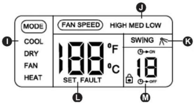
I - Operation mode indicator: COOL, DRY, FAN, HEAT.
J - Fan speed indicator: HIGH, MED, LOW.
K - Swinging indicator (right-left).
M- Display of time setting. The displayed digits indicate the remaining time of the ON/OFF operation.
L - Display of preset temperature - SET and failure code - FAULT. When SET is displayed, the displayed digits indicate the preset temperature. When FAULT is displayed, the displayed digits indicate the code of failure (see chapter: Self-diagnosis function). Room temperature is displayed when the SET and FAULT indicators are not displayed.
NOTICE: The above digits on the LCD display are only for the purpose of explanation. Practically only the pertinent digits are displayed.
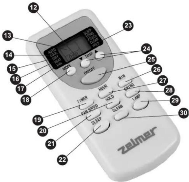
REMOTE CONTROLLER
-
Set on/off time indicator or current time.
-
Preset temperature indicator.
-
Cooling mode: COOL
-
Dehumidifying mode: DRY.
-
Heating mode: HEAT.
-
Ventilation mode FAN.
-
Mode selection button. Each time you press the button the mode will change in the following order: COOL, DRY, HEAT, FAN.
-
TIMER button. Used to set the time of the automatic switch on / switch off of the appliance. When pressed together with the HOUR (27) button, allows to set the time in the 1–12 hour range with an hourly break.
-
Keypad HOLD button.
-
FAN SPEED button. Changes the fan speed from HIGH, MED and LOW.
-
SLEEP button – inactive in this model.
-
HOLD indicator.
-
TEMP button. Each time you press the button the temperature will change by 1°C.
-
ON/OFF button.
-
MIN button. Used to set the current time in minutes.
-
HOUR button. Used to set the current time in hours and the automatic switch on/switch off time in hours.
-
SWING. button. Used to set the air delivery swing mode (left-right) or the fixed direction mode of air delivery.
-
LAMP button – inactive in this model.
-
CLEAN button - inactive in this model.
Technical specification of the remote controller
| Rated voltage 3.0 V | |
| Lowest voltage of CPU emitting signal 2.0 V | |
| Signal receiving range 8 m |
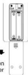
Setting the current time
Properly insert two AAA batteries in the battery compartment on the back of the remote controller (see picture).
After installing the batteries the remote controller will automatically set the time to: 0:00.
For instruction purposes, the time will be set to 10:15.
- Press and hold the HOUR (27) button for about 3 seconds. The time indicator will begin to flash.
- Keep pressing the HOUR (27) button until 10 a.m. is set.
- Press the MIN (26) button, the minute indicator will begin to flash. Keep pressing the button until it is set to 15.
- Press the ON/OFF (25) button to confirm the set time. The set time will be automatically cancelled if the ON/OFF (25) button is not pressed within 15 seconds.
AIR CONDITIONER FUNCTIONS
The air conditioner has four functions: COOL, DRY, FAN ventilation and HEAT.
The temperature range for the cooling mode is from 17°C to 31°C, and for the dehumidifying mode is from 20°C to 31°C.
Power source
- Plug the appliance only to a grounded AC socket connected to a protection circuit.
- Do not connect the appliance to a multiple socket outlet which is also being used for other electrical appliances.
- Insert the plug into a power source. After 2 seconds you will hear a beep. Press the ON/OFF (G) button on the control panel or the ON/OFF (25) button on the remote controller for the appliance to start operating.
Cooling operation
- Repeatedly press the MODE (D) button on the control panel or the MODE (18) button on the remote controller and choose the cooling mode. The LCD display should show the COOL indicator. During the cooling operation always place the air inlet and exhaust hose outside the room e.g. through an open window.
- Repeatedly press TEMP+ or TEMP - (H) button on the control panel or the TEMP (24) button on the remote controller to select the desired room temperature at 17°C - 31°C.
- Press the FAN SPEED (B) button on the control panel or the FAN SPEED (21) button on the remote controller to select the desired fan speed: HIGH, MED, or LOW.
- Press the SWING (E) button on the control panel or the SWING (28) button on the remote controller to adjust the air delivery direction. When the LCD display shows the symbol SWING the swing mode is set (left-right). Otherwise the fixed direction mode of air delivery will be set.
The upper and lower swinging fins (5) can be manually adjusted before the start of operation.
Note: In order to improve the cooling efficiency follow the instructions below:
- Draw the curtains if the room is directly exposed to the sun.
- Do not place the air conditioner near other heat sources.
Dehumidifying operation
- Keep the windows and doors closed for an effective dehumidifying operation.
- Repeatedly press the MODE (D) button on the control panel or the MODE (18) button on the remote controller and choose the dehumidifying mode. The LCD display will show the DRY indicator. During the dehumidifying mode the fan speed cannot be adjusted. (The FAN SPEED button is inactive).
- While using the dehumidifying mode the air conditioner can operate without the air exhaust hose.
Ventilation
- During the ventilation mode the appliance will only adjust the air flow which means that the air flowing into the room will not be cooled or dehumidified.
- Repeatedly press the MODE (D) button on the control panel or the MODE (18) button on the remote controller and choose the ventilation mode. The LCD display should show the FAN indicator. During the ventilation operation always place the air inlet and exhaust hose outside the room e.g. through an open window.
- Press the FAN SPEED (B) button on the control panel or the FAN SPEED (21) button on the remote controller to select the desired fan speed: HIGH, MED, or LOW.
Heating operation
- Repeatedly press the MODE (D) button on the control panel or the MODE (18) button on the remote controller and choose the heating mode. The LCD display should show the HEAT indicator. During the heating operation always place the air inlet and exhaust hose outside the room e.g. through an open window.
- Repeatedly press TEMP+ or TEMP - (H) button on the control panel or the TEMP (24) button on the remote controller to select the desired room temperature at 17°C - 31°C.
- Press the FAN SPEED (B) button on the control panel or the FAN SPEED (21) button on the remote controller to select the desired fan speed: HIGH, MED or LOW.
- Press the SWING (E) button on the control panel or the SWING (28) button on the remote controller to adjust the air delivery direction. When the LCD display shows the symbol SWING; the swing mode is set (left-right). Otherwise the fixed direction mode of air delivery will be set.
The upper and lower swinging fins (5) can be manually adjusted before the start of operation.
AUTOMATIC SWITCH ON / SWITCH OFF USING THE CONTROL PANEL
In order to set the automatic switch on function press the TIMER (A) button, the LCD display will show the symbol „ ON^ . Repeatedly pressing the TIMER (A) button set the time after which the air conditioner is to switch on. Each time you press the TIMER (A) button, the value will increase by one hour. The setting range is 1-12 hours.
In order to set the automatic switch off function of an operating appliance, press the TIMER (A) button, the LCD display will show the symbol „OFF”. Repeatedly pressing the TIMER (A) button set the time after which the air conditioner is to switch off. Each time you press the TIMER (A) button, the value will increase by one hour. The setting range is 1-12 hours.
Note: Pressing the TEMP+ and TEMP – together for more than 2 seconds will lock the buttons. The LCD display will show the symbol ☐Press both buttons together again to unlock the buttons. The symbol will disappear from the display.
AUTOMATIC SWITCH ON / SWITCH OFF USING THE REMOTE CONTROLLER
In order to set the automatic switch on time press the TIMER (19) button. The LCD display of the remote controller will display the „ON” symbol and the last used switch on time in the 1–12H format. Example: „4H“ means that the appliance will automatically switch on in 4 hours.
In order to set / adjust the automatic switch on time press the HOUR (27) button. Each time you press the HOUR (27) button, the value will increase by one hour in the range from 1 to 12. When 12 is reached, the value will return to 1 the next time you press the HOUR (27) button. In order to set the automatic switch off of an operating appliance using the remote controller, press the TIMER (19) button, the LCD display will show the symbol „OFF” and the last used switch off time in the 1–12H format. Example: „4H” means that the appliance will automatically switch off in 4 hours.
In order to set / adjust the automatic switch off time press the HOUR (27) button. Each time you press the HOUR (27) button, the value will increase by one hour in the range from 1 to 12. When 12 is reached, the value will return to 1 the next time you press the HOUR (27) button.
WATER DRAINAGE METHODS
ATTENTION: One of the following drainage methods is suitable for your unit. Please check to refer the identical one and drain the water to proper position.
Method 1: Water drainage pump function – automatic water drainage
- Under random mode if the water level in the water container is LOW, the water pump and recycle pump will not work, the air conditioner operates in the set operation mode.
- If the water level in the water container is NORMAL, the recycle pump will work, water pump will not work and the air conditioner operates in the set operation mode.
- If the water level in the water container is HIGH, the water pump will work for 10 minutes. After that if the water level is on LOW/NORMAL level, the appliance will continue to operate in the set mode. If the water level continues to be on a HIGH level, the water pump will stop working and the appliance will switch off. The WATER FULL (C) control lamp on the control panel will illuminate and the LCD display will show failure code E5. Twist off the release stopper and empty the water container.
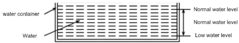
Method 2: Manual water drainage
When the water level in the water container is on HIGH level, the appliance will stop working and the WATER FULL (C) control lamp will illuminate on the control panel. The LCD display will show failure code E5. Simultaneously press the SWING (E) and TIMER (A) buttons for more than 2 seconds. The water will be drained out by the drainage hose at the back of the appliance. When the water level drops to LOW, the appliance will stop draining water. Press the ON/OFF (G) button to continue former operation mode.
CLEANING AND MAINTENANCE
- Unplug the appliance before cleaning.
- Do not use abrasive detergents such as emulsions, cream cleaners, polishes, etc. to clean the housing. They may remove the graphic information symbols.
- Wipe the housing with a damp cloth.
- If the air filter is blocked with a large amount of dust, the air flow volume will be reduced. Clean the air filter every two weeks.
Opening and cleaning the air filter
- Grab the hook on the bottom of the air inlet grill with the filter, pull it out and remove the air filter from the filter cover.
- Wash the air filter by immersing it gently in warm water (about 40°C) with a neutral detergent.
- Rinse the filter and dry in a shady place.
- Attach the filter back to the appliance.
BEFORE THE START OF THE SEASON
- Check if the air inlets and outlets are not blocked.
- Make sure the air filter is properly installed before operating the air conditioner. If the air conditioner is operated with the air filter removed, dust and foreign objects may result in faulty performance of the appliance.
BEFORE THE END OF THE SEASON
- Switch off and unplug the air conditioner.
- Clean the air filter and other parts.
- Twist off the release stopper and remove the water. Run the air conditioner in the ventilation mode for about half a day for the unit to dry thoroughly.
- Cover the appliance to protect it from dust and dirt.
TROUBLESHOOTING
Please check the table below before contacting the service center.
| Problem Check Solution | ||
| The air conditioner does not operate. | Is the power on?Is the appliance unplugged?Has the fuse blown?Is the water container indicator illuminated?Is the water container properly installed?Is the operating time properly set? | Plug in the appliance.Change the fuse.Empty the water container.Correctly install the water container.Change the time settings. |
| Weak cooling effect | Is the air inlet or outlet clogged?Is there another heat source in the room?Are the air filters dirty?Is the temperature correctly set?Is the fan speed appropriate? | Unblock the airflow.Remove the heat source from the room.Clean the filter.Change the set temperature.Change the fan speed to high. |
| Noise and vibration | Is the air conditioner standing on a flat, even surface? | Place the air conditioner on a flat, even surface. |
| The air conditioner automatically switches on and off. | Is the voltage in the power source appropriate?Is the exhaust duct bent or clogged?Is there an additional air outlet independently installed? | Check the power source.Make sure the exhaust duct is in a horizontal position.Check if hot air is correctly channeled. |
ATTENTION: If the air conditioner still does not work, immediately unplug the appliance and contact an authorized service center.
SELF-DIAGNOSIS FUNCTION
The air conditioner has a built-in diagnosis system which informs the user about the improper functioning of the appliance.
| Failure code Failure diagnosis |
| E2 Sucked air temperature measurement failure. |
| E3 Appliance operating at a too high temperature. |
| E4 Appliance protection against irregularities. |
| E5 The water level is too high. |
PERIODIC INSPECTION OF THE APPLIANCE
- Systematically perform obligatory inspections of the appliance every 10–14 months.
- Report the appliance for inspection to the authorized service center.
- The cost of the inspection is covered by the owner of the appliance.
ECOLOGY - ENVIRONMENTAL PROTECTION
Each user can protect the natural environment. It is neither difficult nor expensive.
In order to do it: put the cardboard packing into recycling paper container; put the polyethylene (PE) bags into container for plastic.
When worn out, dispose the appliance to particular disposal centre, because of the dangerous elements of this appliance, which can be hazardous for natural environment.
Do not dispose into the domestic waste disposal!!!
The terms and conditions of the warranty are pursuant to the regulations in force in the country the product is sold.
The manufacturer does not accept any liability for any damages resulting from unintended use or inappropriate handling. The manufacturer reserves his rights for modifying the product any time in order to adjust it to law regulations, norms, directives, or due to construction, trade aesthetic or other reasons, without notifying it in advance.
- PL
- 2-8
- Spis treści
- FUNKCJE KLIMATYZATORA
- OVLÁDACÍ PANEL
- PRAVIDELNÉ PROHLÍDKY PŘÍSTROJE
- LCD DISPLEJ
- KEZELÓPANEL
- LCD KIJELZÖ
- Instalarea tevilor de evacuare a apei
- CARACTERISTICILE APARATULUI
- PANOU DE COMANDĂ
- ПАНЕЛЬ УПРАВЛЕНИЯ
- ХАРАКТЕРИСТИКА НА УРЕДА
- КОНТРОЛЕН ПАНЕЛ
- ПАНЕЛЬ УПРАВЛІННЯ
- LCD - ДИСПЛЕЙ
- Dear Customers!
- INTRODUCTION
- SAFETY INSTRUCTIONS
- Instructions concerning the remote controller
- TECHNICAL PARAMETERS
- INSTALLATION
- The selection of the location
- Air exhaust duct installation
- Duct installation instruction
- Window installation kit
- The installation of the water drainage hose
- APPLIANCE FEATURES
- NAMES OF PARTS
- CONTROL PANEL
- LCD DISPLAY
- REMOTE CONTROLLER
- Technical specification of the remote controller
- Setting the current time
- AIR CONDITIONER FUNCTIONS
- Power source
- Cooling operation
- Note: In order to improve the cooling efficiency follow the instructions below:
- Dehumidifying operation
- Ventilation
- Heating operation
- AUTOMATIC SWITCH ON / SWITCH OFF USING THE CONTROL PANEL
- AUTOMATIC SWITCH ON / SWITCH OFF USING THE REMOTE CONTROLLER
- WATER DRAINAGE METHODS
- Method 1: Water drainage pump function – automatic water drainage
- Method 2: Manual water drainage
- CLEANING AND MAINTENANCE
- Opening and cleaning the air filter
- BEFORE THE START OF THE SEASON
- BEFORE THE END OF THE SEASON
- TROUBLESHOOTING
- SELF-DIAGNOSIS FUNCTION
- PERIODIC INSPECTION OF THE APPLIANCE
- ECOLOGY - ENVIRONMENTAL PROTECTION
Brand : Zelmer
Model : 23Z012
Category : Air-conditioner