
PowerConnect 8024F - Uncategorized DELL - Free user manual and instructions
Find the device manual for free PowerConnect 8024F DELL in PDF.


| Product type | Managed network switch |
| Brand | Dell |
| Model | PowerConnect 8024F |
| Number of ports | 24 ports 10 Gigabit Ethernet SFP+ |
| Port type | SFP+ (fiber optic) |
| Console port | 1 RJ-45 port (serial console) |
| Out-of-band management port | 1 RJ-45 1GbE port |
| Power supply | Dual redundant power supply, 100-240 V AC, 50-60 Hz, 300 W each |
| Power consumption | Up to 600 W (max) |
| Dimensions (W x D x H) | 440 x 420 x 44 mm (1U, 19" rack) |
| Weight | Approximately 8 kg |
| Mounting | 19-inch rack (1U) or standalone |
| Operating temperature | 0 °C to 45 °C |
| Relative humidity | 5% to 95% non-condensing |
| Management features | Web (HTTP/HTTPS), CLI (Telnet/SSH), SNMP |
| Security | AAA authentication, SSH, SSL/TLS, passwords |
| Supported standards | IEEE 802.3ae (10GbE), IEEE 802.3, etc. |
| Package contents | Switch, 2 power cords, RJ45-DB9 console cable, mounting kit, rubber feet, documentation |
| Maintenance | Clean with a dry cloth; do not block ventilation openings |
| Repairability | Replaceable power supplies and fans |
| Warranty | Consult Dell documentation |
Frequently Asked Questions - PowerConnect 8024F DELL
User questions about PowerConnect 8024F DELL
0 question about this device. Answer the ones you know or ask your own.
Ask a new question about this device
Download the instructions for your Uncategorized in PDF format for free! Find your manual PowerConnect 8024F - DELL and take your electronic device back in hand. On this page are published all the documents necessary for the use of your device. PowerConnect 8024F by DELL.
USER MANUAL PowerConnect 8024F DELL
Model PC8024 and PC8024F
Dell™ PowerConnect™
8024 and 8024F Switches
Getting Started Guide
Model PC8024 and PC8024F
Notes, Notices, and Cautions

NOTE: A NOTE indicates important information that helps you make better use of your computer.

NOTICE: A NOTICE indicates either potential damage to hardware or loss of data and tells you how to avoid the problem.

CAUTION: A CAUTION indicates a potential for property damage, personal injury, or death.
Information in this document is subject to change without notice. © 2009 Dell Inc. All rights reserved.
Reproduction in any manner whatsoever without the written permission of Dell Inc. is strictly forbidden.
Trademarks used in this text: Dell, the DELL logo, and PowerConnect are trademarks of Dell Inc.; Microsoft and Windows are registered trademarks of Microsoft Corporation.
Other trademarks and trade names may be used in this document to refer to either the entities claiming the marks and names or their products. Dell Inc. disclaims any proprietary interest in trademarks and trade names other than its own.
Model PC8024 and PC8024F
November 2009 P/N X472K Rev. A02
Contents
Installation
Site Preparation 5
Unpacking the Switch 5
Package Contents. 5
Unpacking Steps 6
Mounting the Switch 6
Installing in a Rack 6
Installing as a Free-standing Switch 7
Connecting a Switch to a Terminal 7
Connecting a Switch to a Power Supply 8
Starting and Configuring the Switch
Connecting the Terminal to the Switch 9
Booting the Switch 10
Initial Configuration 10
Management Interface and Out-of-Band Interface 11
Initial Configuration Procedure. 11
Example Session 12
Advanced Configuration 15
Retrieving an IP Address From a DHCP Server 15
Security Management and Password Configuration. 16
Managing the Switch
Using a Web Browser to Manage the Switch 19
Starting the Application 19
Understanding the Interface 19
Installation
This document provides basic information to install, configure, and operate Dell™ PowerConnect™ 8024 and 8024F systems. For more information, see the User's Guide, which is available on your User Documentation CD, or check the Dell Support web site at support.dell.com for the latest updates on documentation and firmware.
Site Preparation
PowerConnect 8024 and 8024F switches can be mounted in a standard 48.26-cm (19-inch) rack or left freestanding (placed on a flat surface) and function as stand-alone switches.
Before installing the switch or switches, make sure that the chosen installation location meets the following site requirements:
- Power — The switch is installed near an easily accessible 100–250 VAC, 50–60 Hz outlet.
- Clearance — There is adequate front and rear clearance for operator access. Allow clearance for cabling, power connections, and ventilation.
- Cabling — The cabling is routed to avoid sources of electrical noise such as radio transmitters, broadcast amplifiers, power lines, and fluorescent lighting fixtures.
- Ambient — The ambient switch operating temperature range is 0 to 45°C (32 to 113°F) at a relative humidity of up to 95 percent, non-condensing.
Unpacking the Switch
Package Contents
When unpacking each switch, make sure that the following items are included:
• One PowerConnect switch
- Two AC power cables
• One RJ-45 to DB9 female cable
- One rack-mount kit for rack installation (two mounting brackets, bolts, and cage nuts)
• One set of self-adhesive rubber pads for the free-standing switch (four pads are included)
• User Documentation CD
- Getting Started Guide
• Product Information Guide
Unpacking Steps
NOTE: Before unpacking the switch, inspect the container and immediately report any evidence of damage.
1 Place the container on a clean, flat surface and cut all straps securing the container.
2 Open the container or remove the container top.
3 Carefully remove the switch from the container and place it on a secure and clean surface.
4 Remove all packing material.
5 Inspect the product and accessories for damage.
Mounting the Switch
CAUTION: Read the safety information in the Product Information Guide as well as the safety information for other switches that connect to or support the switch.
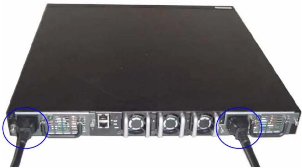
The two AC power connectors are on the back panel of the switch.
Installing in a Rack
CAUTION: Do not use rack mounting kits to suspend the switch from under a table or desk, or attach it to a wall.
CAUTION: Disconnect all cables from the switch before continuing. Remove all self-adhesive pads from the underside of the switch, if they have been attached.
CAUTION: When mounting multiple switches into a rack, mount the switches from the bottom up.
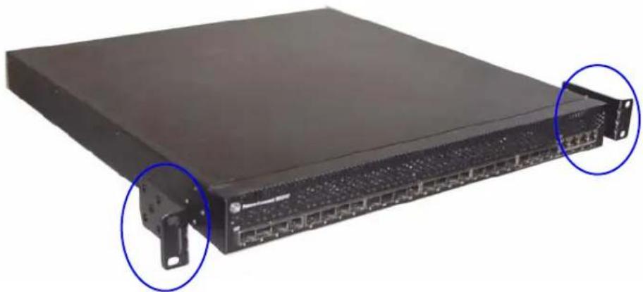
1 Place the supplied rack-mounting bracket on one side of the switch, ensuring that the mounting holes on the switch line up to the mounting holes in the rack-mounting bracket. Figure 1 illustrates where to mount the brackets.
Figure 1. Attaching the Brackets
natural_image
Front view of a black network switch device with two blue-circled ports and mounting brackets (no visible text or labels)2 Insert the supplied bolts into the rack-mounting holes and tighten with a screwdriver.
3 Repeat the process for the rack-mounting bracket on the other side of the switch.
4 Insert the switch into the 48.26 cm (19 inch) rack, ensuring that the rack-mounting holes on the switch line up to the mounting holes in the rack.
5 Secure the switch to the rack with either the rack bolts or cage nuts and cage nut bolts with washers (depending on the kind of rack you have). Fasten the bolts on bottom before fastening the bolts on top.

NOTICE: Make sure that the ventilation holes are not obstructed.

CAUTION: Make sure that the supplied rack bolts fit the pre-threaded holes in the rack.
Installing as a Free-standing Switch

NOTICE: We strongly recommend mounting the switch in a rack.
Install the switch on a flat surface if you are not installing it in a rack. The surface must be able to support the weight of the switch and the switch cables. The switch is supplied with four self-adhesive rubber pads.
1 Attach the self-adhesive rubber pads on each location marked on the bottom of the switch.
2 Set the switch on a flat surface, and make sure that it has proper ventilation by leaving 5 cm (2 inches) on each side and 13 cm (5 inches) at the back.
Connecting a Switch to a Terminal
1 Connect the DB9 connector of the RJ-45-to-DB9 serial cable to a VT100 terminal or to a computer running VT100 terminal emulation software.
2 Connect the RJ-45 connector at the other end to the top RJ-45 port on the rear panel of the switch. For more information about the location of the console port, see Figure 3.
Connecting a Switch to a Power Supply

CAUTION: Read the safety information in the Product Information Guide as well as the safety information for other switches that connect to or support the switch.
The PowerConnect 8024 and 8024F switches have two power supplies for redundant or load-sharing operation. Each power supply can support 300W. Figure 2 illustrates the location of the two power receptacles on the rear panel.
1 Connect one of the supplied AC power cables to one of the AC power connectors located on the rear panel.
2 To provide a redundant source of power, connect the second supplied AC power cable to the other AC power connector located on the rear panel.

NOTE: Do not connect the power cable to a grounded AC outlet at this time. Connect the switch to a power source as described in the step detailed in "Starting and Configuring the Switch".
Figure 2. Connecting Power Cables
natural_image
Back view of a network switch device showing ports, cables, and connectors (no text or symbols visible)Starting and Configuring the Switch
After completing all external connections, connect a terminal to a switch to configure the switch. Additional advanced functions are described in the User's Guide located on your User Documentation CD.

NOTE: Read the release notes for this product before proceeding. You can download the release notes from the Dell Support website at support.dell.com.

NOTE: We recommend that you obtain the most recent version of the user documentation from the Dell Support website at support.dell.com.
Connecting the Terminal to the Switch
To monitor and configure the switch via serial console, use the console port on the rear of the switch to connect it to a VT100 terminal or to a computer running VT100 terminal emulation software. The console port is implemented as a data terminal equipment (DTE) connector.
The following is required to use the console port:
- VT100-compatible terminal or a desktop or a portable system with a serial port, running VT100 terminal emulation software.
- A serial cable (provided) with a RJ-45 connector for the console port and DB9 connector for the terminal.
Perform the following tasks to connect a terminal to the switch console port:
1 Connect the DB9 connector on the serial cable to the terminal running VT100 terminal emulation software.
2 Configure the terminal emulation software as follows:
a Select the appropriate serial port (serial port 1 or serial port 2) to connect to the console.
b Set the data rate to 9600 baud.
c Set the data format to 8 data bits, 1 stop bit, and no parity.
d Set the flow control to none.
e Set the terminal emulation mode to VT100.
f Select Terminal keys for Function, Arrow, and Ctrl keys. Make sure that the setting is for Terminal keys (not Microsoft® Windows® keys).

NOTE: When using HyperTerminal with Microsoft Windows 2000, make sure that you have Windows 2000 Service Pack 2 or later installed. With Windows 2000 Service Pack 2, the arrow keys function properly in HyperTerminal's VT100 emulation. Go to www.microsoft.com for more information on Windows 2000 service packs.
3 Connect the RJ-45 connector on the cable directly to the switch console port. The PowerConnect 8024 and 8024F console port is located on the rear panel, above the RJ-45 out-of-band port, as shown in Figure 3.
Figure 3. Connecting to the Console Port
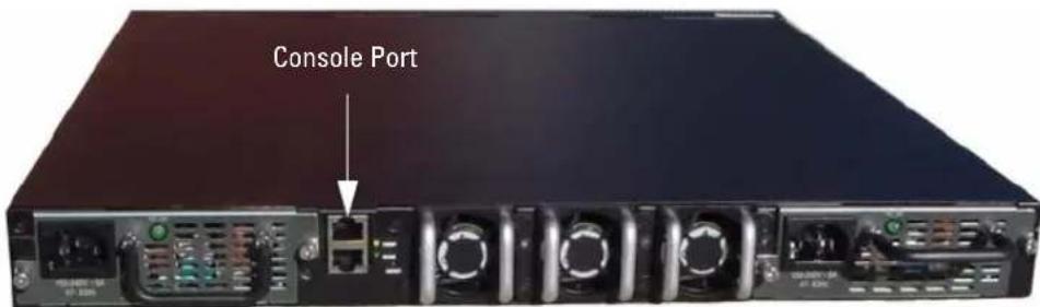
The RJ-45 port below the Console port is for out-of-band management.
Booting the Switch
1 Make sure that the switch console port is connected to a VT100 terminal or VT100 terminal emulator via the RJ-45 to DB9 female cable.
2 Locate two AC power receptacles.
3 Deactivate the AC power receptacle.
4 Connect both of the switch power supplies to the AC receptacles.
5 Activate the AC power receptacles.
When the power is turned on with the local terminal already connected, the switch goes through a power-on self-test (POST). POST runs every time the switch is initialized and checks hardware components to determine if the switch is fully operational before completely booting. If POST detects a critical problem, the program flow stops. If POST passes successfully, valid firmware is loaded into RAM. POST messages are displayed on the terminal and indicate test success or failure. The boot process runs for approximately 60 seconds.
Initial Configuration

NOTE: The initial simple configuration procedure is based on the following assumptions:
- The PowerConnect switch was never configured before and is in the same state as when you received it.
• The PowerConnect switch booted successfully. - The console connection was established and the Dell Easy Setup Wizard prompt appears on the screen of a VT100 terminal or terminal equivalent.
The initial switch configuration is performed through the console port. After the initial configuration, you can manage the switch either from the already-connected console port or remotely through an interface defined during the initial configuration.

NOTE: The switch is not configured with a default user name and password.

NOTE: All of the settings below are necessary to allow the remote management of the switch through Telnet (Telnet client) or HTTP (Web browser).
Before setting up the initial configuration of the switch, obtain the following information from your network administrator:
- The IP address to be assigned to the management VLAN.
- The IP subnet mask for the network.
- The IP address of the management VLAN default gateway.
Management Interface and Out-of-Band Interface
The front panel of the PowerConnect 8024 and 8024F switches contains multiple 10-Gigabit Ethernet ports for data traffic. Additionally, you can use any port on the front panel as the in-band management interface. The rear panel contains a Gigabit Ethernet port for out-of-band (OOB) management. The OOB port is located below the console port.
The Dell Easy Setup Wizard configures network information for the in-band management interface. To use the OOB interface for management, use the Command Line Interface (CLI) to configure network information. You can assign a static IP address and subnet mask or enable DHCP and allow a DHCP server to assign the information automatically.

NOTE: DHCP can be enabled on either the management interface or the OOB interface, but not both. DHCP is enabled by default on the management interface. To use DHCP on the OOB interface, you must first disable it on the management interface and then enable it on the OOB interface.
See the PowerConnect 8024 and 8024F CLI Reference Guide for information about the commands to use to configure the OOB interface.
Initial Configuration Procedure
You can perform the initial configuration using the Dell Easy Setup Wizard, or by using the Command Line Interface (CI.I). The Setup Wizard automatically starts when the switch configuration file is empty. You can exit the wizard at any point by entering [ctrl+z] , but all configuration settings specified will be discarded (the switch will use the default values).

NOTE: If you do not run the Easy Setup Wizard or do not respond to the initial Easy Setup Wizard prompt within 60 seconds, the switch enters CLI mode. If the switch is connected to your network through the management interface when you power it on for the first time, it attempts to acquire an IP address from a DHCP server. If no DHCP server responds to the request within 50 seconds, the switch uses 192.168.2.1 as the default IP address on the management VLAN. To view the management interface IP address, enter the enable command to enter Privileged EXEC mode, and then enter show ip interface management. There is no default IP address for the OOB interface.
For more information on CLI initial configuration see the User Guide. This Getting Started Guide shows how to use the Setup Wizard for initial switch configuration. The wizard sets up the following configuration on the switch:
- Establishes the initial privileged user account with a valid password. The wizard configures one privileged user account during the setup.
- Enables CLI login and HTTP access to use the local authentication setting only.
- Sets up the IP address for the management VLAN.
- Sets up the SNMP community string to be used by the SNMP manager at a given IP address. You may choose to skip this step if SNMP management is not used for this switch.
- Allows you to specify the management server IP or permit management access from all IP addresses.
- Configures the default gateway IP address.
Example Session
This section describes an Easy Setup Wizard session. The following values are used by the example session:
- The SNMP community string to be used is public
• The network management system IP address is 192.168.2.1. - The user name is admin, and password is admin123.
- The IP address for the management VLAN is 192.168.2.1:255.255.255.0.
• The default gateway is 0.0.0.0.
The setup wizard configures the initial values as defined above. After you complete the wizard, the switch is configured as follows:
- SNMPv1/2c is enabled and the community string is set up as defined above. SNMPv3 is disabled by default.
- The admin user account is set up as defined.
- A network management system is configured. From this management station, you can access the SNMP, HTTP, and CLI interfaces. You may also choose to allow all IP addresses to access these management interfaces by choosing the (0.0.0.0) IP address.
- An IP address is configured for the default management VLAN (1).
- A default gateway address is configured.

NOTE: In the example below, the possible user options are enclosed in []. Also, where possible, the default value is provided in {}. If you press
The following example contains the sequence of prompts and responses associated with running an example Dell Easy Setup Wizard session, using the input values listed above.
After the switch completes the POST and is booted, the following dialog appears:
Unit 1 - Waiting to select management unit) >
Applying configuration, please wait ...
Welcome to Dell Easy Setup Wizard
The Setup Wizard guides you through the initial switch configuration, and gets you up and running as quickly as possible. You can skip the setup wizard, and enter CLI mode to manually configure the switch. You must respond to the next question to run the setup wizard within 60 seconds, otherwise the system will continue with normal operation using the default system configuration. Note: You can exit the setup wizard at any point by entering [ctrl+z].
Would you like to run the setup wizard (you must answer this question within 60 seconds)? [Y/N] y
Step 1:
The system is not setup for SNMP management by default. To manage the switch using SNMP (required for Dell Network Manager) you can
. Set up the initial SNMP version 2 account now.
. Return later and setup other SNMP accounts. (For more information on setting up an SNMP version 1 or 3 account, see the user documentation).
Would you like to setup the SNMP management interface now? [Y/N] y
To setup the SNMP management account you must specify the management system IP address and the "community string" or password that the particular management system uses to access the switch. The wizard automatically assigns the highest access level [Privilege Level 15] to this account. You can use Dell Network Manager or other management interfaces to change this setting and to add additional management systems later. For more information on adding management systems, see the User's Guide.
To add a management station:
Please enter the SNMP community string to be used [public]:public
NOTE: If it is configured, the default access level is set to the highest available access for the SNMP management interface. Initially only SNMPv1/2c will be activated. SNMPv3 is disabled until you return to configure security access for SNMPv3 (e.g. engine ID, view, etc.).
Please enter the IP address of the Management System (A.B.C.D) or wildcard (0.0.0.0) to manage from any Management Station {0.0.0.0}: 192.168.2.100
Step 2:
Now we need to setup your initial privilege (Level 15) user account. This account is used to login to the CLI and Web interface. You may setup other accounts and change privilege levels later. For more information on setting up user accounts and changing privilege levels, see the user documentation.
To setup a user account:
Please enter the user name. [admin]:admin Please enter the user password:***** Please reenter the user password:*****
Step 3:
Next, an IP address is setup. The IP address is defined on the default VLAN (VLAN #1), of which all ports are members. This is the IP address you use to access the CLI, Web interface, or SNMP interface for the switch. Optionally you may request that the system automatically retrieve an IP address from the network via DHCP (this requires that you have a DHCP server running on the network).
To setup an IP address:
Please enter the IP address of the device (A.B.C.D) or enter "DHCP" (without the quotes) to automatically request an IP address from the network DHCP server. 192.168.2.1:192.168.2.1
Please enter the IP subnet mask (A.B.C.D or /nn). 255.255.255.0:255.255.255.0
Step 4:
Finally, setup the default gateway. Please enter the IP address of the gateway from which this network is reachable. [0.0.0.0]:
This is the configuration information that has been collected:
SNMP Interface = "public"@192.168.2.100
User Account setup = admin
Password = *****
Management IP address = 192.168.2.1 255.255.255.0
Default Gateway = 0.0.0.0
Operation Mode = Normal
Step 5:
If the information is correct, please select (Y) to save the configuration, and copy to the start-up configuration file. If the information is incorrect, select (N) to discard configuration and restart the wizard: [Y/N] y
Thank you for using Dell Easy Set up Wizard. You will now enter CLI mode.
Advanced Configuration
This section provides summary information about such common tasks as:
• Retrieving an IP Address From a DHCP Server
• Security Management and Password Configuration

NOTE: For detailed information on all the CLI commands available for the 8024 and 8024F M6348 switches, see the CLI Reference Guide.
Retrieving an IP Address From a DHCP Server
When using the DHCP protocol to retrieve an IP address, the switch acts as a DHCP client.
To retrieve an IP address from a DHCP server, perform the following steps:
1 Select and connect any port to a DHCP server or to a subnet that has a DHCP server on it, in order to retrieve the IP address.

NOTE: You do not need to delete the switch configuration to retrieve an IP address for the D HCP server.
2 Enter the following commands to use the selected port for receiving the IP address.
console#config console(config)#ip address dhcp
The interface receives the IP address automatically.
3 To verify the IP address, enter the show ip interface command at the system prompt as shown in the following example.
console#show ip interface
Management Interface:
IP Address.... 10.240.4.125
Subnet Mask.... 255.255.255.0
Default Gateway.... 10.240.4.1
Burned In MAC Address....00:10:18:82:04:35
Network Configuration Protocol Current.... DHCP
Management VLAN ID.... 1
Routing Interfaces:
Netdir Multi
Interface IP Address IP Mask Bcast CastFwd
vlan1 192.168.10.10 255.255.255.0 Disable Disable
vlan2 0.0.0.0 0.0.0.0 Enable Disable
loopback2 0.0.0.0 0.0.0.0 Disable Disable
Security Management and Password Configuration
System security is handled through the AAA (Authentication, Authorization, and Accounting) mechanism that manages user access rights, privileges, and management methods. AAA uses both local and remote user databases. Data encryption is handled through the SSII mechanism.
The system is delivered with no default password configured; all passwords are user-defined. If a user-defined password is lost, a password recovery procedure can be invoked from the Boot menu. The procedure is applicable for the local terminal only and allows a one-time access to the switch from the local terminal with no password entered.
Configuring Security Passwords
The security passwords can be configured for the following services:
- Console
- Telnet
- SSH
- H T T P
- H T T P S

NOTE: When creating a user name, the default priority is "1", which allows access but not configuration rights. A priority of "15" must be set to enable access and configuration rights to the switch.
Configuring an Initial Console Password
To configure an initial console password, enter the following commands:
console(config)#aaa authentication login default line
console(config)#aaa authentication enable default line
console(config)#line console
console(config-line)#login authentication default
console(config-line)#enable authentication default
console(config-line)#password secret123
- When initially logging on to a switch through a console session, enter secret123 at the password prompt.
- When changing a switch's mode to enable, enter secret123 at the password prompt.
Configuring an Initial Telnet Password
To configure an initial Telnet password, enter the following commands:
console(config)#aaa authentication login default line
console(config)#aaa authentication enable default line
console(config)#line telnet
console(config-line)#login authentication default
console(config-line)#enable authentication default
console(config-line)#password pass1234
- When initially logging onto a switch through a Telnet session, enter pass1234 at the password prompt.
- When changing a switch mode to enable, enter pass1234.
Configuring an Initial HTTP Password
To configure an initial HTTP password, enter the following commands:
console(config)#ip http authentication local
console(config)#username admin password user1234 level 15
Configuring an Initial HTTPS Password
To configure an initial HTTPS password, enter the following commands:
console(config)#ip https authentication local
NOTE: You should generate a new crypto certificate each time you upgrade (install a new version of) the control software application on the switch.
Enter the following commands once when configuring to use an HTTPS session over a console, a Telnet, or an SSH session.
NOTE: In the Web browser enable SSL 2.0 or greater for the page content to appear.
console(config)#crypto certificate 1 generate
console(config)#ip https server
NOTE: Http and Https services require level 15 access and connect directly to the configuration level access.
Managing the Switch
You can manage the switch by using the Web-based interface, command-line interface (CLI), or SNMP. To manage the switch by using a Web browser or SNMP, the switch must have an IP address, and it must be accessible from the management station. To manage the switch by using the CLI, you can use a direct console connection or a remote Telnet/SSII connection.
To establish a direct console connection to the CLI, see "Connecting the Terminal to the Switch" on page 9. You can use the Easy Setup Wizard To perform the initial configuration that allows remote management access (see "Initial Configuration Procedure" on page 11). For instructions on configuring remote management using the CLI, refer to the User's Guide.
Using a Web Browser to Manage the Switch
Starting the Application
1 Open a web browser.
2 Enter the switch's IP address (as defined in the CLI) in the address bar and press
3 When the Login window displays, enter a user name and password.

NOTE: The switch is not configured with a default password, and you can configure the switch without entering a password when you connect to the CLI by using the console port. Passwords are both case sensitive and alpha-numeric. For information about recovering a lost password, see the User's Guide.
4 Click OK.
5 The Dell OpenManage Switch Administrator home page displays.
Understanding the Interface
The home page contains the following views:
- Tree view — Located on the left side of the home page, the tree view provides an expandable view of features and their components.
- Device view — Located on the right side of the home page, the device view is used to display such things as a view of the device, an information or table area, and/or configuration instructions.
Dell™ PowerConnect™
8024 和 8024F 交换机
使用入门指南
型号 PC8024 和 PC8024F
注、注意和警告
natural_image
Front view of a black server rack with multiple Ethernet ports and mounting brackets, showing two blue-circled points of interest (no text or symbols visible)natural_image
Back view of a network switch device showing internal ports and connectors (no text or symbols visible)启动和配置交换机
Applying configuration, please wait ... (正在应用配置,请稍候...)
Welcome to Dell Easy Setup Wizard (欢迎使用 Dell 简易安装向导)
The Setup Wizard guides you through the initial switch configuration, and gets you up and running as quickly as possible. You can skip the setup wizard, and enter CLI mode to manually configure the switch. You must respond to the next question to run the setup wizard within 60 seconds, otherwise the system will continue with normal operation using the default system configuration. Note: You can exit the setup wizard at any point by entering [ctrl+z]. (该安装向导将指导您完成初始交换机配置,并尽快使您开机并运行。可以跳过安装向导,进入 CLI 模式以手动配置交换机。您必须在 60 秒之内答复下一个问题才能运行安装向导,否则系统将使用默认的系统配置继续正常运行。注:可以随时通过按 [ctrl+z] 键退出安装向导。)
Would you like to run the setup wizard (you must answer this question within 60 seconds)? [Y/N](是否要运行安装向导 [必须在 60 秒内回答此问题]?[Y/N])y
步骤1:
Now we need to setup your initial privilege (Level 15) user account. This account is used to login to the CLI and Web interface. You may setup other accounts and change privilege levels later. For more information on setting up user accounts and changing privilege levels, see the user documentation.(现在,需要设置初始权限 [级别 15] 用户帐户。该帐户用于登录到 CLI 接口及 Web 接口。稍后,可以设置其它帐户并更改权限级别。有关设置用户帐户和更改权限级别的详情,请参阅用户说明文件。)
To setup a user account: (设置用户帐户:)
Please enter the user name.(请输入用户名。)[admin]:admin
Please enter the user password: (请输入用户密码:) *****
Please reenter the user password: (请重新输入用户密码:) *****
步骤3:
Next, an IP address is setup. The IP address is defined on the default VLAN (VLAN #1), of which all ports are members. This is the IP address you use to access the CLI, Web interface, or SNMP interface for the switch. Optionally you may request that the system automatically retrieve an IP address from the network via DHCP (this requires that you have a DHCP server running on the network).(接下来,设置IP地址。在默认的VLAN [VLAN #1]上定义IP地址,其中的所有端口均是成员。对于交换机,这是用于访问CLI接口、Web接口或SNMP接口的IP地址。另外,您还可以请求系统通过DHCP从网络自动检索IP地址[这要求有DHCP服务器在网络上运行]。)
To setup an IP address: (设置 IP 地址:)
Please enter the IP address of the device (A.B.C.D) or enter "DHCP" (without the quotes) to automatically request an IP address from the network DHCP server. 192.168.2.1: (请输入设备的 IP 地址 [A.B.C.D] 或输入 "DHCP" [不带引号], 自动向网络 DHCP 服务器请求 IP 地址。192.168.2.1: ) 192.168.2.1
Finally, setup the default gateway. Please enter the IP address of the gateway from which this network is reachable. [0.0.0.0]: (最后,设置默认网关。请输入通过其可访问网络的网关 IP 地址。[0.0.0.0]:)
This is the configuration information that has been collected: (以下是已收集的配置信息:)
SNMP Interface (SNMP 接口) = "public"@192.168.2.100
User Account setup = (用户帐户设置 =) admin
Password = ****** (密码 = ******)
Operation Mode = Normal (运行模式 = 正常)
步骤5:
If the information is correct, please select (Y) to save the configuration, and copy to the start-up configuration file. If the information is incorrect, select (N) to discard configuration and restart the wizard: [Y/N](如果信息正确,请选择 [Y] 保存配置,并将其复制到启动配置文件。如果信息不正确,请选择 [N] 丢弃配置,然后重新启动向导:[Y/N]) y
Burned In MAC Address(固化 MAC 地址)....00:10:18:82:04:35
Network Configuration Protocol Current(当前网络配置协议)...DHCP
Routing Interfaces: (路由接口:)
Netdir Multi
Interface IP Address IP Mask Bcast CastFwd
(接口) (IP 地址) (IP 掩码)
vlan1 192.168.10.10 255.255.255.0 Disable
(禁用) Disable (禁用)
natural_image
Front view of a black server rack with multiple Ethernet ports and mounting brackets, showing two blue-circled connectors (no text or symbols visible)natural_image
Back panel of a network switch device showing ports, cables, and connectors (no text or symbols visible)啟動和設定交換機
The Setup Wizard guides you through the initial switch configuration, and gets you up and running as quickly as possible. You can skip the setup wizard, and enter CLI mode to manually configure the switch. You must respond to the next question to run the setup wizard within 60 seconds, otherwise the system will continue with normal operation using the default system configuration. Note: You can exit the setup wizard at any point by entering [ctrl+z]. (設定精靈指導您完成初始的交換機組態,讓您盡快使用交換機。您可以跳過設定精靈,進入 CLI 模式以手動方式設定交換機。必須回答下一個問題,在 60 秒內執行設定精靈,否則系統將繼續使用預設的系統組態正常作業。註:可以隨時透過輸入 [ctrl+z] 鍵結束設定精靈。)
Would you like to run the setup wizard (you must answer this question within 60 seconds)? [Y/N] y (要執行安裝精靈 [必須在 60 秒內回答該問題] 嗎? [Y/N]) y
步驟1:
The system is not setup for SNMP management by default. To manage the switch using SNMP (required for Dell Network Manager) you can (系統預設並未設定用於 SNMP 管理。若要使用 SNMP 管理交換機 (Dell Network Manager 所必需),您可以)
Next, an IP address is setup. The IP address is defined on the default VLAN (VLAN #1), of which all ports are members. This is the IP address you use to access the CLI, Web interface, or SNMP interface for the switch. Optionally you may request that the system automatically retrieve an IP address from the network via DHCP (this requires that you have a DHCP server running on the network). (接下來設定 IP 位址。IP 位址在預設的 VLAN (VLAN #1) 上設定,所有連接埠均為此 VLAN 的成員。此 IP 位址用於存取交換機的 CLI、Web 介面或 SNMP 介面。您可以請求系統透過 DHCP 自動從網路擷取 IP 位址 [必須有 DHCP 伺服器在網路上執行])。
To setup an IP address: (若要設定 IP 位址:)
Please enter the IP address of the device (A.B.C.D) or enter "DHCP" (without the quotes) to automatically request an IP address from the network DHCP server. (請輸入裝置的 IP 位址 [A.B.C.D] 或輸入 "DHCP" [不帶引號],自動向網路 DHCP 伺服器請求 IP 位址)。
Please enter the IP subnet mask (A.B.C.D or /nn). (請輸入 IP 子網路遮罩 (A.B.C.D 或 /nn))。255.255.255.0:255.255.255.0
步驟4:
Finally, setup the default gateway. Please enter the IP address of the gateway from which this network is reachable. [0.0.0.0]:
This is the configuration information that has been collected: (以下是已收集的組態資訊:)
SNMP Interface (SNMP 介面) = "public"@192.168.2.100
User Account setup (使用者帳戶設定) = admin
Burned In MAC Address (燒錄 MAC 位址) .....00:10:18:82:04:35
Network Configuration Protocol Current (目前網路設定協定)... DHCP
Management VLAN ID (管理 VLAN ID).... 1
Routing Interfaces: (路由介面:)
Netdir Multi
Interface IP Address IP Mask Bcast CastFwd
(介面) (IP
位址)(IP
遮罩)
vlan1 192.168.10.10 255.255.255.0 Disable (
停用)Disable(停用)
vlan2 0.0.0.0 0.0.0.0 Enable (
啟用)Disable(停用)
loopback2 0.0.0.0
0.0.0.0
Disable (
停用)Disable(停用)
安全管理和密碼設定
natural_image
Front view of a black server rack with two blue circular annotations pointing to its side (no visible text or symbols)natural_image
Back view of a black network switch device with multiple ports and connectors, showing two blue circular annotations pointing to ports with visible internal components.(Unit 1 - Waiting to select management unit) >
Applying configuration, please wait ...
Welcome to Dell Easy Setup Wizard
The Setup Wizard guides you through the initial switch configuration, and gets you up and running as quickly as possible. You can skip the setup wizard, and enter CLI mode to manually configure the switch. You must respond to the next question to run the setup wizard within 60 seconds, otherwise the system will continue with normal operation using the default system configuration. Note: You can exit the setup wizard at any point by entering [ctrl+z].
Would you like to run the setup wizard (you must answer this question within 60 seconds)? [Y/N] y
Étapel:
The system is not setup for SNMP management by default. To manage the switch using SNMP (required for Dell Network Manager) you can:
. Set up the initial SNMP version 2 account now.
. Return later and setup other SNMP accounts. (For more information on setting up an SNMP version 1 or 3 account, see the user documentation).
Would you like to setup the SNMP management interface now? [Y/N] y
To setup the SNMP management account you must specify the management system IP address and the "community string" or password that the particular management system uses to access the switch. The wizard automatically assigns the highest access level [Privilege Level 15] to this account. You can use Dell Network Manager or other management interfaces to change this setting and to add additional management systems later. For more information on adding management systems, see the User's Guide.
To add a management station:
Please enter the IP address of the Management System (A.B.C.D) or wildcard (0.0.0.0) to manage from any Management Station {0.0.0.0}: 192.168.2.100
Étape2:
Now we need to setup your initial privilege (Level 15) user account. This account is used to login to the CLI and Web interface. You may setup other accounts and change privilege levels later. For more information on setting up user accounts and changing privilege levels, see the user documentation.
To setup a user account:
Please enter the user name. [admin]:admin Please enter the user password:***** Please reenter the user password:*****
Étape 3 :
Next, an IP address is setup. The IP address is defined on the default VLAN (VLAN #1), of which all ports are members. This is the IP address you use to access the CLI, Web interface, or SNMP interface for the switch. Optionally you may request that the system automatically retrieve an IP address from the network via DHCP (this requires that you have a DHCP server running on the network).
To setup an IP address:
Please enter the IP address of the device (A.B.C.D) or enter "DHCP" (without the quotes) to automatically request an IP address from the network DHCP server. 192.168.2.1:192.168.2.1
Please enter the IP subnet mask (A.B.C.D or /nn). 255.255.255.0:255.255.255.0
Étape 4 :
Finally, setup the default gateway. Please enter the IP address of the gateway from which this network is reachable. [0.0.0.0]:
This is the configuration information that has been collected:
SNMP Interface = "public"@192.168.2.100
User Account setup = admin
Password = *****
Management IP address = 192.168.2.1 255.255.255.0
Default Gateway = 0.0.0.0
Operation Mode = Normal
Étape 5 :
If the information is correct, please select (Y) to save the configuration, and copy to the start-up configuration file. If the information is incorrect, select (N) to discard configuration and restart the wizard: [Y/N] y
Thank you for using Dell Easy Set up Wizard. You will now enter CLI mode.
Configuration avancée
Management Interface:
IP Address.... 10.240.4.125
Subnet Mask.... 255.255.255.0
Default Gateway.... 10.240.4.1
Burned In MAC Address....00:10:18:82:04:35
Network Configuration Protocol Current.... DHCP
Management VLAN ID.... 1
Routing Interfaces:
| Interface | Adresse | IP | Masque | Netdir | Multi | CastFwd |
| IP | Bcast |
| vlan1 192.168.10.10 255.255.255.0 Disable Disable |
| vlan2 0.0.0.0 0.0.0.0 Enable Disable |
| loopback2 0.0.0.0 0.0.0.0 Disable Disable |
- Console
- Telnet
- SSH
- H T T P
• II T T P S

November 2009 Teilenr. X472K Rev. A02
Inhalt
Installation
natural_image
Front view of a black server rack with two blue-circled connectors attached to its side (no visible text or labels)natural_image
Back view of a network switch device showing ports, cables, and connectors (no text or symbols visible)Unit 1 - Waiting to select management unit) >
Applying configuration, please wait ...
Welcome to Dell Easy Setup Wizard
The Setup Wizard guides you through the initial switch configuration, and gets you up and running as quickly as possible. You can skip the setup wizard, and enter CLI mode to manually configure the switch. You must respond to the next question to run the setup wizard within 60 seconds, otherwise the system will continue with normal operation using the default system configuration. Note: You can exit the setup wizard at any point by entering [ctrl+z].
Would you like to run the setup wizard (you must answer this question within 60 seconds)? [Y/N] y
Schritt 1:
The system is not setup for SNMP management by default. To manage the switch using SNMP (required for Dell Network Manager) you can
. Set up the initial SNMP version 2 account now.
. Return later and setup other SNMP accounts. (For more information on setting up an SNMP version 1 or 3 account, see the user documentation).
Would you like to setup the SNMP management interface now? [Y/N] y
To setup the SNMP management account you must specify the management system IP address and the "community string" or password that the particular management system uses to access the switch. The wizard automatically assigns the highest access level [Privilege Level 15] to this account. You can use Dell Network Manager or other management interfaces to change this setting and to add additional management systems later. For more information on adding management systems, see the User's Guide.
To add a management station:
Please enter the SNMP community string to be used [public]:public

Please enter the IP address of the Management System (A.B.C.D) or wildcard (0.0.0.0) to manage from any Management Station {0.0.0.0}: 192.168.2.100
Schritt 2:
Now we need to setup your initial privilege (Level 15) user account. This account is used to login to the CLI and Web interface. You may setup other accounts and change privilege levels later. For more information on setting up user accounts and changing privilege levels, see the user documentation.
To setup a user account:
Please enter the user name. [admin]:admin Please enter the user password:***** Please reenter the user password:*****
Schritt 3:
Next, an IP address is setup. The IP address is defined on the default VLAN (VLAN #1), of which all ports are members. This is the IP address you use to access the CLI, Web interface, or SNMP interface for the switch. Optionally you may request that the system automatically retrieve an IP address from the network via DHCP (this requires that you have a DHCP server running on the network).
To setup an IP address:
Please enter the IP address of the device (A.B.C.D) or enter "DHCP" (without the quotes) to automatically request an IP address from the network DHCP server. 192.168.2.1:192.168.2.1
Please enter the IP subnet mask (A.B.C.D or /nn).
Schritt 4:
Finally, setup the default gateway. Please enter the IP address of the gateway from which this network is reachable. [0.0.0.0]:
This is the configuration information that has been collected:
SNMP Interface = "public"@192.168.2.100
User Account setup = admin
Password = *****
Management IP address = 192.168.2.1 255.255.255.0
Default Gateway = 0.0.0.0
Operation Mode = Normal
Schritt 5:
If the information is correct, please select (Y) to save the configuration, and copy to the start-up configuration file. If the information is incorrect, select (N) to discard configuration and restart the wizard: [Y/N] y
Thank you for using Dell Easy Set up Wizard. You will now enter CLI mode.
Fortgeschrittene Konfiguration
Management Interface:
IP Address.... 10.240.4.125
Subnet Mask.... 255.255.255.0
Default Gateway.... 10.240.4.1
Burned In MAC Address....00:10:18:82:04:35
Network Configuration Protocol Current...... DHCP
Management VLAN ID.... 1
Routing Interfaces:
Netdir Multi
Interface IP Address IP Mask Bcast CastFwd
vlan1 192.168.10.10 255.255.255.0 Disable Disable
vlan2 0.0.0.0 0.0.0.0 Enable Disable
loopback2 0.0.0.0 0.0.0.0 Disable Disable
November 2009 No. Komp. X472K Rev. A02
Daftar lsi
Instalasi
natural_image
Front view of a black server rack with two blue-circled connectors (no visible text or labels)natural_image
Back view of a network switch device showing ports, cables, and connectors (no text or symbols visible)Unit 1 - Waiting to select management unit) >
Applying configuration, please wait ...
Welcome to Dell Easy Setup Wizard
The Setup Wizard guides you through the initial switch configuration, and gets you up and running as quickly as possible. You can skip the setup wizard, and enter CLI mode to manually configure the switch. You must respond to the next question to run the setup wizard within 60 seconds, otherwise the system will continue with normal operation using the default system configuration. Note: You can exit the setup wizard at any point by entering [ctrl+z].
Would you like to run the setup wizard (you must answer this question within 60 seconds)? [Y/N] y
Langkah 1:
The system is not setup for SNMP management by default. To manage the switch using SNMP (required for Dell Network Manager) you can
. Set up the initial SNMP version 2 account now.
. Return later and setup other SNMP accounts. (For more information on setting up an SNMP version 1 or 3 account, see the user documentation).
Would you like to setup the SNMP management interface now? [Y/N] y
To setup the SNMP management account you must specify the management system IP address and the "community string" or password that the particular management system uses to access the switch. The wizard automatically assigns the highest access level [Privilege Level 15] to this account. You can use Dell Network Manager or other management interfaces to change this setting and to add additional management systems later. For more information on adding management systems, see the User's Guide.
To add a management station:
Please enter the SNMP community string to be used [public]:public

Please enter the IP address of the Management System (A.B.C.D) or wildcard (0.0.0.0) to manage from any Management Station {0.0.0.0}: 192.168.2.100
Langkah 2:
Now we need to setup your initial privilege (Level 15) user account. This account is used to login to the CLI and Web interface. You may setup other accounts and change privilege levels later. For more information on setting up user accounts and changing privilege levels, see the user documentation.
To setup a user account:
Please enter the user name. [admin]:admin Please enter the user password:***** Please reenter the user password:*****
Langkah 3:
Next, an IP address is setup. The IP address is defined on the default VLAN (VLAN #1), of which all ports are members. This is the IP address you use to access the CLI, Web interface, or SNMP interface for the switch. Optionally you may request that the system automatically retrieve an IP address from the network via DHCP (this requires that you have a DHCP server running on the network).
To setup an IP address:
Please enter the IP address of the device (A.B.C.D) or enter "DHCP" (without the quotes) to automatically request an IP address from the network DHCP server. 192.168.2.1:192.168.2.1
Please enter the IP subnet mask (A.B.C.D or /nn).
Langkah 4:
Finally, setup the default gateway. Please enter the IP address of the gateway from which this network is reachable. [0.0.0.0]:
This is the configuration information that has been collected:
SNMP Interface = "public"@192.168.2.100
User Account setup = admin
Password = *****
Management IP address = 192.168.2.1 255.255.255.0
Default Gateway = 0.0.0.0
Operation Mode = Normal
Langkah 5:
If the information is correct, please select (Y) to save the configuration, and copy to the start-up configuration file. If the information is incorrect, select (N) to discard configuration and restart the wizard: [Y/N] y
Thank you for using Dell Easy Set up Wizard. You will now enter CLI mode.
Konfigurasi Lanjutan
Management Interface:
IP Address.... 10.240.4.125
Subnet Mask.... 255.255.255.0
Default Gateway.... 10.240.4.1
Burned In MAC Address....00:10:18:82:04:35
Network Configuration Protocol Current...... DHCP
Management VLAN ID.... 1
Routing Interfaces:
| Netdir | Multi | |
| Interface IP Address IP Mask | Bcast |
| vlan1 192.168.10.10 255.255.255.0 Disable Disable |
| vlan2 0.0.0.0 0.0.0.0 Enable Disable |
| loopback2 0.0.0.0 0.0.0.0 Disable Disable |
natural_image
Front view of a black server rack with multiple Ethernet ports and two blue-circled connectors (no visible text or labels)natural_image
Front view of a network switch device showing ports, cables, and connectors (no text or symbols visible)スイッチの起動と設定
Unit 1 - Waiting to select management unit) >
Applying configuration, please wait ...
Welcome to Dell Easy Setup Wizard
The Setup Wizard guides you through the initial switch configuration, and gets you up and running as quickly as possible. You can skip the setup wizard, and enter CLI mode to manually configure the switch. You must respond to the next question to run the setup wizard within 60 seconds, otherwise the system will continue with normal operation using the default system configuration. Note: You can exit the setup wizard any time by entering [ctrl+z].
Would you like to run the setup wizard (you must answer this question within 60 seconds)? [Y/N] y
手順1:
The system is not setup for SNMP management by default. To manage the switch using SNMP (required for Dell Network Manager) you can
. Set up the initial SNMP version 2 account now.
. Return later and setup other SNMP accounts. (For more information on setting up an SNMP version 1 or 3 account, see the user documentation).
Would you like to setup the SNMP management interface now? [Y/N] y
To setup the SNMP management account you must specify the management system IP address and the "community string" or password that the particular management system uses to access the switch. The wizard automatically assigns the highest access level [Privilege Level 15] to this account. You can use Dell Network Manager or other management interfaces to change this setting and to add additional management systems later. For more information on adding management systems, see the User's Guide.
To add a management station:
Please enter the SNMP community string to be used [public]:public
Please enter the IP address of the Management System (A.B.C.D) or wildcard (0.0.0.0) to manage from any Management Station {0.0.0.0}: 192.168.2.100
手順2:
Now we need to setup your initial privilege (Level 15) user account. This account is used to login to the CLI and Web interface. You may setup other accounts and change privilege levels later. For more information on setting up user accounts and changing privilege levels, see the user documentation.
To setup a user account:
Please enter the user name. [admin]:admin
Please enter the user password:*******
Please reenter the user password:*******
手順3:
Next, an IP address is setup. The IP address is defined on the default VLAN (VLAN #1), of which all ports are members. This is the IP address you use to access the CLI, Web interface, or SNMP interface for the switch. Optionally you may request that the
system automatically retrieve an IP address from the network via DHCP (this requires that you have a DHCP server running on the network).
To setup an IP address:
Please enter the IP address of the device (A.B.C.D) or enter "DHCP" (without the quotes) to automatically request an IP address from the network DHCP server. 192.168.2.1:192.168.2.1
Please enter the IP subnet mask (A.B.C.D or /nn). 255.255.255.0:255.255.255.0
手順 4 :
Finally, setup the default gateway. Please enter the IP address of the gateway from which this network is reachable. [0.0.0.0]:
This is the configuration information that has been collected:
SNMP Interface = "public"@192.168.2.100
User Account setup = admin
Password = *****
Management IP = 192.168.2.1 255.255.255.0
Default Gateway = 0.0.0.0
Operation Mode = Normal
手順5:
If the information is correct, please select (Y) to save the configuration, and copy to the start-up configuration file. If the information is incorrect, select (N) to discard configuration and restart the wizard: [Y/N] y
Thank you for using Dell Easy Set up Wizard. You will now enter CLI mode.
詳細設定
Management Interface:
IP Address.... 10.240.4.125
Subnet Mask.... 255.255.255.0
Default Gateway.... 10.240.4.1
Burned In MAC Address....00:10:18:82:04:35
Network Configuration Protocol Current.... DHCP
Management VLAN ID.... 1
Routing Interfaces:
Netdir Multi
Interface IP Address IP Mask Bcast CastFwd
vlan1 192.168.10.10 255.255.255.0 Disable Disable
vlan2 0.0.0.0 0.0.0.0 Enable Disable
loopback2 0.0.0.0 0.0.0.0 Disable Disable
セキュリティ管理とパスワードの設定
natural_image
Front view of a black network switch device with two blue-circled connectors (no visible text or labels)natural_image
Back view of a network switch device showing ports, cables, and connectors (no text or symbols visible)스위치 시작 및 구성
Unit 1 - Waiting to select management unit) >
Applying configuration, please wait ...
Welcome to Dell Easy Setup Wizard
The Setup Wizard guides you through the initial switch configuration, and gets you up and running as quickly as possible. You can skip the setup wizard, and enter CLI mode to manually configure the switch. You must respond to the next question to run the setup wizard within 60 seconds, otherwise the system will continue with normal operation using the default system configuration. Note: You can exit the setup wizard at any point by entering [ctrl+z].
Would you like to run the setup wizard (you must answer this question within 60 seconds)? [Y/N] y
1 단계:
The system is not setup for SNMP management by default. To manage the switch using SNMP (required for Dell Network Manager) you can
. Set up the initial SNMP version 2 account now.
. Return later and setup other SNMP accounts. (For more information on setting up an SNMP version 1 or 3 account, see the user documentation).
Would you like to setup the SNMP management interface now? [Y/N] y
To setup the SNMP management account you must specify the management system IP address and the "community string" or password that the particular management system uses to access the switch. The wizard automatically assigns the highest access level [Privilege Level 15] to this account. You can use Dell Network Manager or other management interfaces to change this setting and to add additional management systems later. For more information on adding management systems, see the User's Guide.
To add a management station:
Please enter the SNMP community string to be used [public]:public

Please enter the IP address of the Management System (A.B.C.D) or wildcard (0.0.0.0) to manage from any Management Station {0.0.0.0}: 192.168.2.100
2 단계:
Now we need to setup your initial privilege (Level 15) user account. This account is used to login to the CLI and Web interface. You may setup other accounts and change privilege levels later. For more information on setting up user accounts and changing privilege levels, see the user documentation.
To setup a user account:
Please enter the user name. [admin]:admin Please enter the user password:***** Please reenter the user password:*****
3 단계:
Next, an IP address is setup. The IP address is defined on the default VLAN (VLAN #1), of which all ports are members. This is the IP address you use to access the CLI, Web interface, or SNMP interface for the switch. Optionally you may request that the system automatically retrieve an IP address from the network via DHCP (this requires that you have a DHCP server running on the network).
To setup an IP address:
Please enter the IP address of the device (A.B.C.D) or enter "DHCP" (without the quotes) to automatically request an IP address from the network DHCP server. 192.168.2.1:192.168.2.1
Please enter the IP subnet mask (A.B.C.D or /nn). 255.255.255.0:255.255.255.0
4 단계:
Finally, setup the default gateway. Please enter the IP address of the gateway from which this network is reachable. [0.0.0.0]:
This is the configuration information that has been collected:
SNMP Interface = "public"@192.168.2.100 User Account setup = admin Password = ***** Management IP address = 192.168.2.1 255.255.255.0 Default Gateway = 0.0.0.0 Operation Mode = Normal
5 단계:
If the information is correct, please select (Y) to save the configuration, and copy to the start-up configuration file. If the information is incorrect, select (N) to discard configuration and restart the wizard: [Y/N] y
Thank you for using Dell Easy Set up Wizard. You will now enter CLI mode.
고급 구성
Management Interface:
IP Address.... 10.240.4.125
Subnet Mask.... 255.255.255.0
Default Gateway.... 10.240.4.1
Burned In MAC Address....00:10:18:82:04:35
Network Configuration Protocol Current.... DHCP
Management VLAN ID.... 1
Routing Interfaces:
Netdir Multi Interface IP Address IP Mask Bcast CastFwd
vlan1 192.168.10.10 255.255.255.0 Disable Disable
vlan2 0.0.0.0 0.0.0.0 Enable Disable
loopback2 0.0.0.0 0.0.0.0 Disable Disable
보안 관리 및 암호 구성
natural_image
Front view of a black server rack with two blue-circled connectors (no visible text or labels)natural_image
Back panel of a network switch device showing ports, cables, and connectors (no visible text or labels)Unit 1 - Waiting to select management unit) >
Applying configuration, please wait ...
Welcome to Dell Easy Setup Wizard
The Setup Wizard guides you through the initial switch configuration, and gets you up and running as quickly as possible. You can skip the setup wizard, and enter CLI mode to manually configure the switch. You must respond to the next question to run the setup wizard within 60 seconds, otherwise the system will continue with normal operation using the default system configuration. Note: You can exit the setup wizard at any point by entering [ctrl+z].
Would you like to run the setup wizard (you must answer this question within 60 seconds)? [Y/N] y
Paso 1:
The system is not setup for SNMP management by default. To manage the switch using SNMP (required for Dell Network Manager) you can
. Set up the initial SNMP version 2 account now.
. Return later and setup other SNMP accounts. (For more information on setting up an SNMP version 1 or 3 account, see the user documentation).
Would you like to setup the SNMP management interface now? [Y/N] y
To setup the SNMP management account you must specify the management system IP address and the "community string" or password that the particular management system uses to access the switch. The wizard automatically assigns the highest access level [Privilege Level 15] to this account. You can use Dell Network Manager or other management interfaces to change this setting and to add additional management systems later. For more information on adding management systems, see the User's Guide.
To add a management station:
Please enter the SNMP community string to be used [public]:public

Please enter the IP address of the Management System (A.B.C.D) or wildcard (0.0.0.0) to manage from any Management Station {0.0.0.0}: 192.168.2.100
Paso 2:
Now we need to setup your initial privilege (Level 15) user account. This account is used to login to the CLI and Web interface. You may setup other accounts and change privilege levels later. For more information on setting up user accounts and changing privilege levels, see the user documentation.
To setup a user account:
Please enter the user name. [admin]:admin
Please enter the user password:*******
Please reenter the user password:*****
Paso 3:
Next, an IP address is setup. The IP address is defined on the default VLAN (VLAN #1), of which all ports are members. This is the IP address you use to access the CLI, Web interface, or SNMP interface for the switch. Optionally you may request that the system automatically retrieve an IP address from the network via DHCP (this requires that you have a DHCP server running on the network).
To setup an IP address:
Please enter the IP address of the device (A.B.C.D) or enter "DHCP" (without the quotes) to automatically request an IP address from the network DHCP server. 192.168.2.1:192.168.2.1
Please enter the IP subnet mask (A.B.C.D or /nn).
Paso 4:
Finally, setup the default gateway. Please enter the IP address of the gateway from which this network is reachable. [0.0.0.0]:
This is the configuration information that has been collected:
SNMP Interface = "public"@192.168.2.100
User Account setup = admin
Password = *****
Management IP address = 192.168.2.1 255.255.255.0
Default Gateway = 0.0.0.0
Operation Mode = Normal
Paso 5:
If the information is correct, please select (Y) to save the configuration, and copy to the start-up configuration file. If the information is incorrect, select (N) to discard configuration and restart the wizard: [Y/N] y
Thank you for using Dell Easy Set up Wizard. You will now enter CLI mode.
Management Interface:
IP Address.... 10.240.4.125
Subnet Mask.... 255.255.255.0
Default Gateway.... 10.240.4.1
Burned In MAC Address....00:10:18:82:04:35
Network Configuration Protocol Current.... DHCP
Management VLAN ID.... 1
Routing Interfaces:
Netdir Multi
Interface IP Address IP Mask Bcast CastFwd
vlan1 192.168.10.10 255.255.255.0 Disable Disable
vlan2 0.0.0.0 0.0.0.0 Enable Disable
loopback2 0.0.0.0 0.0.0.0 Disable Disable
Kasim 2009 P/N X472K Rev. A02
İçerik
Montaj
Saha Hazırlığı 189
natural_image
Front view of a black server rack with multiple Ethernet ports and mounting bracket (no visible text or labels)natural_image
Back view of a network switch device showing ports, cables, and connectors (no text or symbols visible)Unit 1 - Waiting to select management unit) >
Applying configuration, please wait ...
Welcome to Dell Easy Setup Wizard
The Setup Wizard guides you through the initial switch configuration, and gets you up and running as quickly as possible. You can skip the setup wizard, and enter CLI mode to manually configure the switch. You must respond to the next question to run the setup wizard within 60 seconds, otherwise the system will continue with normal operation using the default system configuration. Note: You can exit the setup wizard at any point by entering [ctrl+z].
Would you like to run the setup wizard (you must answer this question within 60 seconds)? [Y/N] y
1. Adım:
The system is not setup for SNMP management by default. To manage the switch using SNMP (required for Dell Network Manager) you can
. Set up the initial SNMP version 2 account now.
. Return later and setup other SNMP accounts. (For more information on setting up an SNMP version 1 or 3 account, see the user documentation).
Would you like to setup the SNMP management interface now? [Y/N] y
To setup the SNMP management account you must specify the management system IP address and the "community string" or password that the particular management system uses to access the switch. The wizard automatically assigns the highest access level [Privilege Level 15] to this account. You can use Dell Network Manager or other management interfaces to change this setting and to add additional management systems later. For more information on adding management systems, see the User's Guide.
To add a management station:
Please enter the SNMP community string to be used [public]:public
Please enter the IP address of the Management System (A.B.C.D) or wildcard (0.0.0.0) to manage from any Management Station {0.0.0.0}: 192.168.2.100
2. Adım:
Now we need to setup your initial privilege (Level 15) user account. This account is used to login to the CLI and Web interface. You may setup other accounts and change privilege levels later. For more information on setting up user accounts and changing privilege levels, see the user documentation.
To setup a user account:
Please enter the user name. [admin]:admin Please enter the user password:***** Please reenter the user password:*****
3. Adım:
Next, an IP address is setup. The IP address is defined on the default VLAN (VLAN #1), of which all ports are members. This is the IP address you use to access the CLI, Web interface, or SNMP interface for the switch. Optionally you may request that the system automatically retrieve an IP address from the network via DHCP (this requires that you have a DHCP server running on the network).
To setup an IP address:
Please enter the IP address of the device (A.B.C.D) or enter "DHCP" (without the quotes) to automatically request an IP address from the network DHCP server. 192.168.2.1:192.168.2.1
Please enter the IP subnet mask (A.B.C.D or /nn).
4. Adım:
Finally, setup the default gateway. Please enter the IP address of the gateway from which this network is reachable. [0.0.0.0]:
This is the configuration information that has been collected:
SNMP Interface = "public"@192.168.2.100
User Account setup = admin
Password = *****
Management IP address = 192.168.2.1 255.255.255.0
Default Gateway = 0.0.0.0
Operation Mode = Normal
5. Adım:
If the information is correct, please select (Y) to save the configuration, and copy to the start-up configuration file. If the information is incorrect, select (N) to discard configuration and restart the wizard: [Y/N] y
Thank you for using Dell Easy Set up Wizard. You will now enter CLI mode.
Management Interface:
IP Address.... 10.240.4.125
Subnet Mask.... 255.255.255.0
Default Gateway.... 10.240.4.1
Burned In MAC Address.... 00:10:18:82:04:35
Network Configuration Protocol Current.... DHCP
Management VLAN ID.... 1
Routing Interfaces:
| Netdir | Multi | |
| Interface IP Address IP Mask | Bcast | CastFwd |
vlan1 192.168.10.10 255.255.255.0 Disable Disable
vlan2 0.0.0.0 0.0.0.0 Enable Disable
loopback2 0.0.0.0 0.0.0.0 Disable Disable
Management Interface:
IP Address.... 10.240.4.125
Subnet Mask.... 255.255.255.0
Default Gateway.... 10.240.4.1
Burned In MAC Address....00:10:18:82:04:35
Network Configuration Protocol Current.... DHCP
Management VLAN ID.... 1
Routing Interfaces:
Netdir Multi
| Interface | IP Address | IP Mask | Bcast | CastFwd |
| vlan1 | 192.168.10.10 | 255.255.255.0 | Disable | Disable |
| vlan2 | 0.0.0.0 | 0.0.0.0 | Enable | Disable |
| loopback2 | 0.0.0.0 | 0.0.0.0 | Disable | Disable |
תאכלהה
Finally, setup the default gateway. Please enter the IP address of the gateway from which this network is reachable. [0.0.0.0]:
This is the configuration information that has been collected:
SNMP Interface = "public"@192.168.2.100
User Account setup = admin
Password = *****
Management IP address = 192.168.2.1 255.255.255.0
Default Gateway = 0.0.0.0
Operation Mode = Normal
176:5
If the information is correct, please select (Y) to save the configuration, and copy to the start-up configuration file. If the information is incorrect, select (N) to discard configuration and restart the wizard: [Y/N] y
Thank you for using Dell Easy Set up Wizard. You will now enter CLI mode.
תָרִיְשָׁה
18024F, -1 8024 von M6348 – M6348 – CLI – M6348 – CLI – CLI – CLI – CLI – CLI – CLI – CLI – CLI – CLI – CLI – CLI – CLI – CLI – CLI – CLI – CLI – CLI – CLI – CLI – CLI – CLI – CLI – CLI – CLI – CLI – CLI – CLI – CLI – CLI – CLI – CLI – CLI – CLI – CLI – CLI – CLI – CLI – CLI – CLI – CLI – CLI – CLI – CLI – CLI – CLI – CLI – CLI – CLI – CLI – CLI –
.CLI Reference Guide-1

Please enter the IP address of the Management System (A.B.C.D) or wildcard (0.0.0.0) to manage from any Management Station {0.0.0.0}: 192.168.2.100
:2 Industry
Now we need to setup your initial privilege (Level 15) user account. This account is used to login to the CLI and Web interface. You may setup other accounts and change privilege levels later. For more information on setting up user accounts and changing privilege levels, see the user documentation.
To setup a user account:
Please enter the user name. [admin]:admin Please enter the user password:***** Please reenter the user password:*****
:3 177
Next, an IP address is setup. The IP address is defined on the default VLAN (VLAN #1), of which all ports are members. This is the IP address you use to access the CLI, Web interface, or SNMP interface for the switch. Optionally you may request that the system automatically retrieve an IP address from the network via DHCP (this requires that you have a DHCP server running on the network).
To setup an IP address:
Please enter the IP address of the device (A.B.C.D) or enter "DHCP" (without the quotes) to automatically request an IP address from the network DHCP server. 192.168.2.1:192.168.2.1
Please enter the IP subnet mask (A.B.C.D or /nn). 255.255.255.0:255.255.255.0
Unit 1 - Waiting to select management unit) >
Applying configuration, please wait...
Welcome to Dell Easy Setup Wizard
The Setup Wizard guides you through the initial switch configuration, and gets you up and running as quickly as possible. You can skip the setup wizard, and enter CLI mode to manually configure the switch. You must respond to the next question to run the setup wizard within 60 seconds, otherwise the system will continue with normal operation using the default system configuration. Note: You can exit the setup wizard at any point by entering [ctrl+z].
Would you like to run the setup wizard (you must answer this question within 60 seconds)? [Y/N] y
:1 וַרָה
The system is not setup for SNMP management by default. To manage the switch using SNMP (required for Dell Network Manager) you can
. Set up the initial SNMP version 2 account now.
. Return later and setup other SNMP accounts. (For more information on setting up an SNMP version 1 or 3 account, see the user documentation).
Would you like to setup the SNMP management interface now? [Y/N] y
To setup the SNMP management account you must specify the management system IP address and the "community string" or password that the particular management system uses to access the switch. The wizard automatically assigns the highest access level [Privilege Level 15] to this account. You can use Dell Network Manager or other management interfaces to change this setting and to add additional management systems later. For more information on adding management systems, see the User's Guide.
To add a management station :
Please enter the SNMP community string to be used [public]:public
•
+. supporting.dell.com.

natural_image
Front view of a black server rack with multiple ports and connectors, showing two blue circular annotations pointing to ports (no text or symbols visible)natural_image
Front view of a black server rack with two blue-circled connectors, showing internal network ports and mounting brackets (no text or symbols visible)תְקַרָה

- Getting Started Guide
- Notes, Notices, and Cautions
- Contents
- Installation
- Starting and Configuring the Switch
- Managing the Switch
- Site Preparation
- Unpacking the Switch
- Package Contents
- Unpacking Steps
- Mounting the Switch
- Installing in a Rack
- Installing as a Free-standing Switch
- Connecting a Switch to a Terminal
- Connecting a Switch to a Power Supply
- Connecting the Terminal to the Switch
- Booting the Switch
- Initial Configuration
- Management Interface and Out-of-Band Interface
- Initial Configuration Procedure
- Example Session
- Step 1:
- Step 2:
- Step 3:
- Step 4:
- Step 5:
- Advanced Configuration
- Retrieving an IP Address From a DHCP Server
- Security Management and Password Configuration
- Configuring Security Passwords
- Configuring an Initial Console Password
- Configuring an Initial Telnet Password
- Configuring an Initial HTTP Password
- Configuring an Initial HTTPS Password
- Using a Web Browser to Manage the Switch
- Starting the Application
- Understanding the Interface
- Dell™ PowerConnect™
- 和 8024F 交换机
- 使用入门指南
- 注、注意和警告
- 启动和配置交换机
- 步骤1:
- 步骤3:
- 步骤5:
- 啟動和設定交換機
- 步驟1:
- 步驟4:
- 安全管理和密碼設定
- Étapel:
- Étape2:
- Étape 3 :
- Étape 4 :
- Étape 5 :
- Configuration avancée
- Inhalt
- Schritt 1:
- Schritt 2:
- Schritt 3:
- Schritt 4:
- Schritt 5:
- Fortgeschrittene Konfiguration
- Daftar lsi
- Instalasi
- Langkah 1:
- Langkah 2:
- Langkah 3:
- Langkah 4:
- Langkah 5:
- Konfigurasi Lanjutan
- スイッチの起動と設定
- 手順1:
- 手順2:
- 手順3:
- 手順 4 :
- 手順5:
- 詳細設定
- セキュリティ管理とパスワードの設定
- 스위치 시작 및 구성
- 단계:
- 단계:
- 단계:
- 단계:
- 단계:
- 고급 구성
- 보안 관리 및 암호 구성
- Paso 1:
- Paso 2:
- Paso 3:
- Paso 4:
- Paso 5:
- İçerik
- Montaj
- Adım:
- Adım:
- Adım:
- Adım:
- Adım:
- תאכלהה
- תְקַרָה
Brand : DELL
Model : PowerConnect 8024F
Category : Uncategorized