
KDC-2027SG - Car radio KENWOOD - Free user manual and instructions
Find the device manual for free KDC-2027SG KENWOOD in PDF.


| Product type | Car stereo |
| Brand | KENWOOD |
| Model | KDC-2027SG |
| Installation dimensions (W x H x D) | 182 x 53 x 155 mm |
| Weight | 1.4 kg |
| Power supply | 14.4 V DC (11-16 V allowable) |
| Current consumption | 10 A (fuse 10 A) |
| Operating voltage | 14.4 V DC |
| Maximum output power | 45 W x 4 |
| DIN output power (45324, +B=14.4 V) | 28 W x 4 |
| Tuner receiver | FM / MW / LW |
| FM frequency range | 87.5 – 108.0 MHz (50 kHz spacing) |
| MW frequency range | 531 – 1611 kHz (9 kHz spacing) |
| LW frequency range | 153 – 281 kHz |
| CD player | Yes (CD, CD-R, CD-RW finalized) |
| Signal-to-noise ratio (CD) | 93 dB |
| Preamp output | 2000 mV / 10 kΩ (impedance ≤ 600 Ω) |
| Detachable faceplate | Yes (theft deterrent) |
| Audio functions | System Q, Loudness, Attenuator, Balance, Bass/Mid/Treble adjustment |
| Clock | Display and adjustment |
| DSI indicator | Red flashing (theft deterrent) |
| Connectors | ISO (power and speakers), AM/FM antenna, TEL MUTE input |
| Contact cleaning | Dry, soft cloth |
| Operating temperature | 0 °C to 40 °C (no condensation) |
Frequently Asked Questions - KDC-2027SG KENWOOD
User questions about KDC-2027SG KENWOOD
0 question about this device. Answer the ones you know or ask your own.
Ask a new question about this device
Download the instructions for your Car radio in PDF format for free! Find your manual KDC-2027SG - KENWOOD and take your electronic device back in hand. On this page are published all the documents necessary for the use of your device. KDC-2027SG by KENWOOD.
USER MANUAL KDC-2027SG KENWOOD
MANUAL DE INSTRUÇÕES
KENWOOD CORPORATION
© B64-2722-00 / 00 (EW/EN)
Safety precautions......3
About CDs....5
General features ......6
Power
Selecting the Source
Volume
Attenuator
Loudness
System Q
Audio Control
Speaker Setting
Clock Display
Adjusting Clock
DSI (Disabled System Indicator)
Theft Deterrent Faceplate
Tuner features....9
Tuning Mode
Tuning
Monaural Reception
Station Preset Memory
Auto Memory Entry
Preset Tuning
CD player features......11
Playing CD
Fast Forwarding and Reversing
Track Search
Track Repeat
Track Scan
Random Play
Accessories 13
Installation Procedure ...... 13
Connecting Wires
to Terminals ....14
Installation 15
Troubleshooting Guide ......17
Specifications ...... 19
▲WARNING
To prevent injury and/or fire, take the following precautions:
- Insert the unit all the way until it is fully locked in place. Otherwise it may fly out of place during collisions and other jolts.
- When extending the ignition, battery or ground wires, make sure to use automotive-grade wires or other wires with an area of 0.75mm2 (AWG18) or more to prevent wire deterioration and damage to the wire coating.
- To prevent short circuits, never put or leave any metallic objects (e.g., coins or metal tools) inside the unit.
- If the unit starts to emit smoke or strange smells, turn off the power immediately and consult your Kenwood dealer.
- Make sure not to get your fingers caught between the faceplate and the unit.
- Be careful not to drop the unit or subject it to strong shock.
The unit may break or crack because it contains glass parts. - Do not touch the liquid crystal fluid if the LCD is damaged or broken due to shock. The liquid crystal fluid may be dangerous to your health or even fatal.
If the liquid crystal fluid from the LCD contacts your body or clothing, wash it off with soap immediately.
▲CAUTION
To prevent damage to the machine, take the following precautions:
- Make sure to ground the unit to a negative 12V DC power supply.
- Do not open the top or bottom covers of the unit.
- Do not install the unit in a spot exposed to direct sunlight or excessive heat or humidity. Also avoid places with too much dust or the possibility of water splashing.
- Do not set the removed faceplate or the faceplate case in areas exposed to direct sunlight, excessive heat or humidity. Also avoid places with too much dust or the possibility of water splashing.
- To prevent deterioration, do not touch the terminals of the unit or faceplate with your fingers.
- Do not subject the faceplate to excessive shock, as it is a piece of precision equipment.
- When replacing a fuse, only use a new one with the prescribed rating. Using a fuse with the wrong rating may cause your unit to malfunction.
- To prevent short circuits when replacing a fuse, first disconnect the wiring harness.
- Do not place any object between the faceplate and the unit.
- During installation, do not use any screws except for the ones provided. The use of improper screws might result in damage to the main unit.
Do Not Load 8-cm (3-in.) CDs in the CD slot
If you try to load an 8-cm CD with its adapter into the unit, the adapter might separate from the CD and damage the unit.
NOTE
- If you experience problems during installation, consult your Kenwood dealer.
- If the unit does not seem to be working right, try pressing the reset button first. If that does not solve the problem, consult your Kenwood dealer.
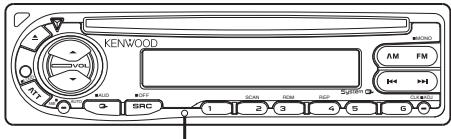
Reset button
- Characters in the LCD may become difficult to read in temperatures below 41 °F (5 °C).
- The illustrations of the display and the panel appearing in this manual are examples used to explain more clearly how the controls are used. Therefore, what appears on the display in the illustrations may differ from what appears on the display on the actual equipment, and some of the illustrations on the display may represent something impossible in actual operation.
Lens Fogging
Right after you turn on the car heater in cold weather, dew or condensation may form on the lens in the CD player of the unit. Called lens fogging, CDs may be impossible to play. In such a situation, remove the disc and wait for the condensation to evaporate. If the unit still does not operate normally after a whilst, consult your Kenwood dealer.
Cleaning the Faceplate Terminals
If the terminals on the unit or faceplate get dirty, wipe them with a dry, soft cloth.
Cleaning the Unit
If the faceplate of this unit is stained, wipe it with a dry soft cloth such as a silicon cloth. If the faceplate is stained badly, wipe the stain off with a cloth moistened with neutral cleaner, then wipe neutral detergent off.

Applying spray cleaner directly to the unit may affect its mechanical parts. Wiping the faceplate with a hard cloth or using a volatile liquid such as thinner or alcohol may scratch the surface or erases characters.
Cleaning the CD Slot
As dust can accumulate in the CD slot, clean it occasionally. Your CDs can get scratched if you put them in a dusty CD slot.

The marking of products using lasers (Except for some areas)
CLASS 1 LASER PRODUCT
The label is attached to the chassis/case and says that the component uses laser beams that have been classified as Class 1. It means that the unit is utilizing laser beams that are of a weaker class. There is no danger of hazardous radiation outside the unit.
This Product is not installed by the manufacturer of a vehicle on the production line, nor by the professional importer of a vehicle into an EU Member State.
Handling CDs
- Don't touch the recording surface of the CD.

- CD-R and CD-RW are easier to damage than a normal music CD. Use a CD-R or a CD-RW after reading the caution items on the package etc.
- Don't stick tape etc. on the CD. Also, don't use a CD with tape stuck on it.
When using a new CD
If the CD center hole or outside rim has burrs, use it after removing them with a ball pen etc.
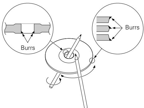
CD accessories
Don't use disc type accessories.
CD cleaning
Clean from the center of the disc and move outward.

Removing CDs
When removing CDs from this unit pull them out horizontally.
CDs that can't be used
- CDs that aren't round can't be used.

- CDs with coloring on the recording surface or that are dirty can't be used.
- This unit can only play the CDs with
It may not correctly play discs which do not have the mark. - A CD-R or CD-RW that hasn't been finalized can't be played. (For the finalization process refer to your CD-R/CD-RW writing software, and your CD-R/CD-RW recorder instruction manual.)

CD storage
- Don't place them in direct sunlight (On the seat or dashboard etc.) and where the temperature is high.
- Store CDs in their cases.
Release button
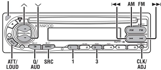

Power
Turning ON the Power
Press the [SRC] button.
Turning OFF the Power
Press the [SRC] button for at least 1 second.
Selecting the Source
Press the [SRC] button.
| Source required | Display |
| Tuner | "TUnE" |
| CD | "CD" |
| Standby (Illumination only mode) | "STBY" |
Volume
Increasing Volume
Press the [^] button.
Decreasing Volume
Press the [∨] button.
Attenuator
Turning the volume down quickly.
Press the [ATT] button.
Each time the button is pressed the Attenuator turns ON or OFF.
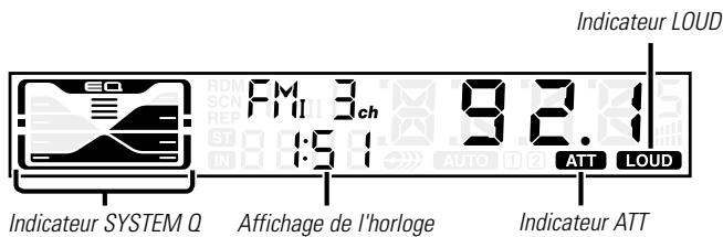
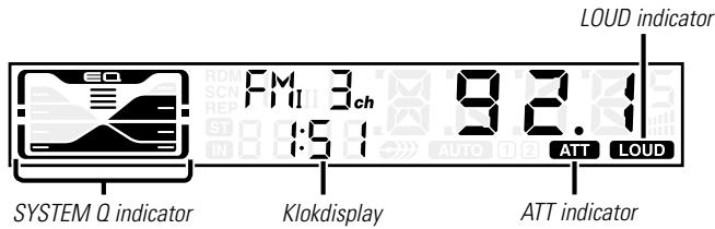
When it's ON, the "ATT" indicator blinks.
Loudness
Compensating for low and high tones during low volume.
Press the [LOUD] button for at least 1 second.
Each time the button is pressed for at least 1 second the
Loudness turns ON or OFF.
When it's ON, "LOUD" indicator is ON.
System Q
You can recall the best sound setting preset for different types of the music.
1 Select the source to set
Press the [SRC] button.
2 Select the Sound type
Press the [Q] button.
Each time the button is pressed the sound setting switches.
| Sound setting | Display |
| Flat | "FLAT" |
| Rock | "ROCK" |
| Top 40 | "TP40" |
| Pops | "POPS" |
| Jazz | "JAZZ" |
| Easy | "EASY" |

- Each setting value is changed with the
First, select the speaker type with the Speaker setting.
- When the System Q setting is changed, the Bass, Middle, and Treble set in audio control replace the System Q values.
Audio Control
1 Select the source for adjustment
Press the [SRC] button.
2 Enter Audio Control mode
Press the [AUD] button for at least 1 second.
3 Select the Audio item for adjustment
Press the [FM] or [AM] button.
Each time the button is pressed the items that can be adjusted switch as shown below.
4 Adjust the Audio item
Press the [◀◀] or [▶▶] button.
| Adjustment Item | Display | Range |
| Bass level | "BAS" | -8 — +8 |
| Middle level | "MID" | -8 — +8 |
| Treble level | "TRE" | -8 — +8 |
| Balance | "BL" | Left 15 — Right 15 |
| Fader | "FD" | Rear 15 — Front 15 |
5 Exit Audio Control mode
Press the [AUD] button.
Speaker Setting
Fine-tuning so that the System Q value is optimal when setting the speaker type.
1 Enter Standby
Press the [SRC] button.
Select the "STBY" display.
2 Enter Speaker Setting mode
Press the [Q] button.
3 Select the Speaker type
Press the [◀◀] or [▶▶] button.
Each time the button is pressed the setting switches as shown below.
| Speaker type | Display |
| OFF | "SP-F" |
| For the OEM speaker | "SP-O" |
| For 6 & 6x9 in. speaker | "SP-6" |
| For 5 & 4 in. speaker | "SP-5" |
4 Exit Speaker Setting mode
Press the [Q] button.
Clock Display
Press the [CLK] button.
Each time the button is pressed the clock display turns ON or OFF.
Adjusting Clock
1 Select the clock display
Press the [CLK] button.
2 Enter clock adjustment mode
Press the [ADJ] button for at least 2 seconds.
The clock display blinks.
3 Adjust the hours
Press the [FM] or [AM] button.
Adjust the minutes
Press the [◀◀] or [▶▶] button.
4 Exit clock adjustment mode
Press the [CLK] button.
DSI (Disabled System Indicator)
A red indicator will blink on the unit after the faceplate is removed, warning potential thieves.
1 Turn the power OFF
Press the [SRC] button for at least 1 second.
2 Set the DSI
While pressing the [1] and [3] button, press the [SRC] button. Each time the step 1 and 2 operation is done the DSI turns ON or OFF.
Theft Deterrent Faceplate
The faceplate of the unit can be detached and taken with you, helping to deter theft.
Removing the Faceplate
Press the Release button.
The faceplate is unlocked, allowing you to detach it.

- The faceplate is a precision piece of equipment and can be damaged by shocks or jolts. For that reason, keep the faceplate in its special storage case while detached.
- Do not expose the faceplate or its storage case to direct sunlight or excessive heat or humidity. Also avoid places with too much dust or the possibility of water splashing.
Reattaching the Faceplate
1 Align the projections on the unit with the grooves on the faceplate.

2 Push the faceplate in until it clicks.
The faceplate is locked in place, allowing you to use the unit.

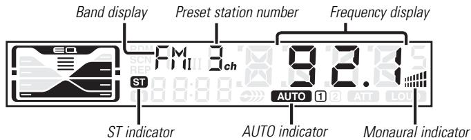
Tuning Mode
Choose the tuning mode.
Press the [AUTO] button.
Each time the button is pressed the Tuning mode switches as shown below.
| Tuning mode | Display | Operation |
| Auto seek | "AUTO 1" indicator | Automatic search for a station. |
| Preset station seek | "AUTO 2" indicator | Search in order of the stations in the Preset memory. |
| Manual | — | Normal manual tuning control. |
Tuning
Selecting the station.
1 Select tuner source
Press the [SRC] button.
Select the "TUnE" display.
2 Select the band
Press the [FM] or [AM] button.
Each time the [FM] button is pressed it switches between the FM1, FM2, and FM3 bands.
3 Tune up or down band
Press the [◀◀] or [▶▶] button.

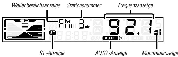
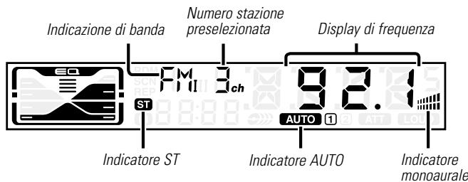
During reception of stereo stations the "ST" indicator is ON.
Monaural Reception
Noise can be reduced when stereo broadcasts are received as monaural.
Press the [MONO] button for at least 1 second.
Each time the button is pressed for at least 1 second the
Monaural Reception turns ON or OFF.
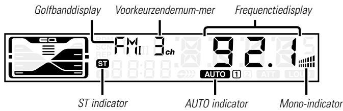
When it's ON, the Monaural indicator is ON.
Station Preset Memory
Putting the station in the memory.
1 Select the band
Press the [FM] or [AM] button.
2 Select the frequency to put in the memory
Press the [◀◀] or [▶▶] button.
3 Put the frequency in the memory
Press the [1] — [6] button for at least 2 seconds.
The preset number display blinks 1 time.
On each band, 1 station can be put in the memory on each [1] — [6] button.
Auto Memory Entry
Putting stations with good reception in the memory automatically.
1 Select the band for Auto Memory Entry
Press the [FM] or [AM] button.
2 Open Auto Memory Entry
Press the [AME] button for at least 2 seconds.
When 6 stations that can be received are put in the memory Auto Memory Entry closes.

Preset Tuning
Calling up the stations in the memory.
1 Select the band
Press the [FM] or [AM] button.
2 Call up the station
Press the [1] — [6] button.
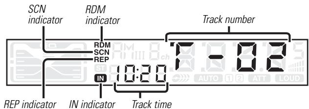
Playing CD
When a CD is inserted
Press the [SRC] button.
Select the "CD" display.

When a CD is inserted, the "IN" indicator is ON.
Eject the CD
Press the [▲] button.

3 in. (8cm) CD cannot be played. Using an adapter and inserting them into this unit can cause damage.
Fast Forwarding and Reversing
Fast Forwarding
Hold down on the [▶▶] button.
Release your finger to play the disc at that point.
Reversing
Hold down on the [◀◀] button.
Release your finger to play the disc at that point.
Track Search
Selecting the song you want to hear.
Press the [◀◀] or [▶▶] button.
Track Repeat
Replaying the song you're listening to.
Press the [REP] button.
Each time the button is pressed the Track Repeat turns ON or OFF.
When it's ON, the "REP" indicator is ON.
Track Scan
Playing the first part of each song on the disc you are listening to and searching for the song you want to listen to.
1 Start Track Scan
Press the [SCAN] button.
"SCN" indicator is ON.
2 Release it when the song you want to listen to is played Press the [SCAN] button.
Random Play
Playing all the songs on the disc in random order.
Press the [RDM] button.
Each time the button is pressed Random Play turns ON or OFF. When it's ON, the "RDM" indicator is ON and the track number blinks.

When the [▶▶] button is pressed, the next song select starts.
Accessories
| External view | Number of items | |
| 1 |  | 1 |
| 2 | 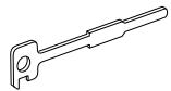 | 2 |
| 3 |  | 1 |

The use of any accessories except for those provided might result in damage to the unit. Make sure only to use the accessories shipped with the unit, as shown above.
Installation Procedure
- To prevent short circuits, remove the key from the ignition and disconnect the terminal of the battery.
- Make the proper input and output wire connections for each unit.
- Connect the wire on the wiring harness.
- Take Connector B on the wiring harness and connect it to the speaker connector in your vehicle.
- Take Connector A on the wiring harness and connect it to the external power connector on your vehicle.
- Connect the wiring harness connector to the unit.
- Install the unit in your car.
- Reconnect the terminal of the battery.
- Press the reset button.
▲CAUTION
- If your car is not prepared for this special connection-system, consult your Kenwood dealer.
- Only use antenna conversion adapters (ISO-JASO) when the antenna cord has an ISO plug.
- Make sure that all wire connections are securely made by inserting jacks until they lock completely.
- If your vehicle's ignition does not have an ACC position, or if the ignition wire is connected to a power source with constant voltage such as a battery wire, the power will not be linked with the ignition (i.e., it will not turn on and off along with the ignition). If you want to link the unit's power with the ignition, connect the ignition wire to a power source that can be turned on and off with the ignition key.
- If the fuse blows, first make sure that the wires have not caused a short circuit, then replace the old fuse with one with the same rating.
- Insulate unconnected wires with vinyl tape or other similar material. To prevent short circuits, also do not remove the caps on the ends of the unconnected wires or the terminals.
- Connect the speaker wires correctly to the terminals to which they correspond. The unit may receive damage or fail to work if you share the wires and/or ground them to any metal part in the car.
- After the unit is installed, check whether the brake lamps, indicators, wipers, etc. on the car are working properly.
- If the console has a lid, make sure to install the unit so that the faceplate does not hit the lid when closing and opening.
- Mount the unit so that the mounting angle is 30° or less.
Connector Function Guide
| Pin Numbers for ISO Connectors | Wire Color | Functions |
| External Power Connector | ||
| A-4 | Yellow | Battery |
| A-5 | Blue/White | Power Control |
| A-7 | Red | Ignition (ACC) |
| A-8 | Black | Earth (Ground) Connection |
| Speaker Connector | ||
| B-1 | Purple | Rear Right (+) |
| B-2 | Purple/Black | Rear Right (-) |
| B-3 | Gray | Front Right (+) |
| B-4 | Gray/Black | Front Right (-) |
| B-5 | White | Front Left (+) |
| B-6 | White/Black | Front Left (-) |
| B-7 | Green | Rear Left (+) |
| B-8 | Green/Black | Rear Left (-) |
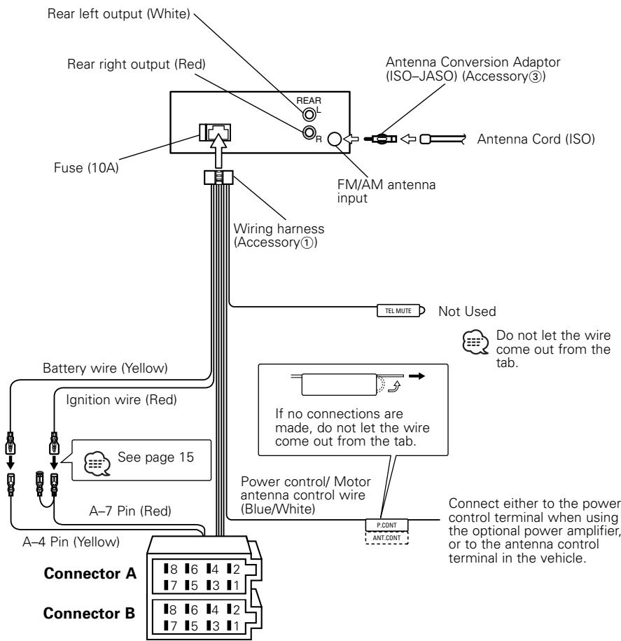
▲WARNING Connecting the ISO Connector (see p.14)
The pin arrangement for the ISO connectors depends on the type of vehicle you drive. Make sure to make the proper connections to prevent damage to the unit.
The default connection for the wiring harness is described in 1 below. If the ISO connector pins are set as described in 2 or 3, make the connection as illustrated.
Please be sure to reconnect the cable as shown ② below to install this unit to the Volkswagen vehicles etc.
① (Default setting) The A-7 pin (red) of the vehicle's ISO connector is linked with the ignition, and the A-4 pin (yellow) is connected to the constant power supply.
![graph LR A["Ignition cable (Red)"] --> B["Unit"] --> C["Vehicle"] --> D["A-7 Pin (Red)"] E["Battery cable (Yellow)"] --> F["Unit"] --> G["Vehicle"] --> H["A-4 Pin (Yellow)"]](/content/2019/11/83708/images/0f00096214595952b8cab5dc9452aba1975d402c7b795a2c346de9fc605a9911.jpg)
② The A-7 pin (red) of the vehicle's ISO connector is connected to the constant power supply, and the A-4 pin (yellow) is linked to the ignition.
![graph LR A["Ignition cable (Red)"] --> B["Unit"] C["Battery cable (Yellow)"] --> D["Unit"] B --> E["Vehicle"] D --> F["Vehicle"] E --> G["A-7 Pin (Red)"] F --> H["A-4 Pin (Yellow)"]](/content/2019/11/83708/images/32785f64cd654f70cde76a044a7b8861aa72a23ad41bb6836884582c7254c825.jpg)
3 The A-4 pin (yellow) of the vehicle's ISO connector is not connected to anything, while the A-7 pin (red) is connected to the constant power supply (or both the A-7 (red) and A-4 (yellow) pins are connected to the constant power supply).
![graph LR A["Ignition cable (Red)"] --> B["Unit"] B --> C["Vehicle"] C --> D["A-7 Pin (Red)"] E["Battery cable (Yellow)"] --> F["Unit"] F --> G["Vehicle"] G --> H["A-4 Pin (Yellow)"]](/content/2019/11/83708/images/194d9c688808a0adff3a8eb03274a1c2312c82464d7c9b12d979f486dd7402c5.jpg)

When the connection is made as in 3 above, the unit's power will not be linked to the ignition key. For that reason, always make sure to turn off the unit's power when the ignition is turned off.
To link the unit's power to the ignition, connect the ignition cable (ACC...red) to a power source that can be turned on and off with the ignition key.
■ Installation
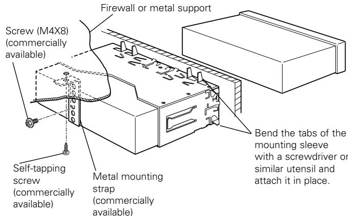

Make sure that the unit is installed securely in place. If the unit is unstable, it may malfunction (eg, the sound may skip).
■ Removing the hard rubber frame
1 Engage the catch pins on the removal tool and remove the two locks on the lower level. Lower the frame and pull it forward as shown in the figure.

2 When the lower level is removed, remove the upper two locations.
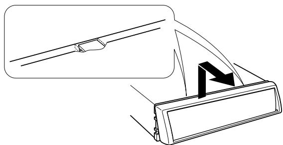

The frame can be removed from the top side in the same manner.
■ Removing the Unit
1 Refer to the section "Removing the hard rubber frame" and then remove the hard rubber frame.
2 Remove the screw (M4×8) on the back panel.
3 Insert the two removal tools deeply into the slots on each side, as shown.

4 Lower the removal tool toward the bottom, and pull out the unit halfway while pressing towards the inside.
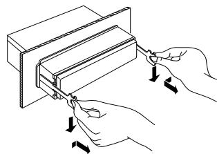
Be careful to avoid injury from the catch pins on the removal tool.
5 Pull the unit all the way out with your hands, being careful not to drop it.

What might seem to be a malfunction in your unit may just be the result of slight misoperation or miswiring. Before calling service, first check the following table for possible problems.
General
? The power does not turn ON.
√ The fuse has blown. E After checking for short circuits in the wires, replace the fuse with one with the same rating.
√ No ACC position on vehicle ignition. Connect the same wire to the ignition as the battery wire.
? Nothing happens when the buttons are pressed.
√ The computer chip in the unit is not functioning normally. Press the reset button on the unit (page 4).
? There's a source you can't switch.
√ There's no CD inserted. Set the media you want to listen to. If there's no media in this unit, you can't switch to each source.
? The memory is erased when the ignition is turned OFF.
√ The battery wire has not been connected to the proper terminal.
Connect the wire correctly, referring to the section on
√ The ignition and battery wire are incorrectly connected.
Connect the wire correctly, referring to the section on
? Even if Loudness is turned ON, high-pitched tone isn't compensated for.
√ Tuner source is selected. ▶ High-pitched tone isn't compensated for when in Tuner source.
? No sound can be heard, or the volume is low.
√ The fader or balance settings are set all the way to one side. ☑ Center the fader and balance settings.
√ The input/output wires or wiring harness are connected incorrectly.
☑ Reconnect the input/output wires or the wiring harness correctly.
See the section on
? The sound quality is poor or distorted.
√ One of the speaker wires is being pinched by a screw in the car. Check the speaker wiring.
√ The speakers are not wired correctly. ■ Reconnect the speaker wires so that each output terminal is connected to a different speaker.
? The Touch Sensor Tone doesn't sound.
√ The preout jack is being used. The Touch Sensor Tone can't be output from the preout jack.
Tuner source
? Radio reception is poor.
√ The car antenna is not extended.
▶ Pull the antenna out all the way.
√ The antenna control wire is not connected.
▶ Connect the wire correctly, referring to the section on
Disc source
? The specified disc does not play, but another one plays instead.
√ The specified CD is quite dirty.
Clean the CD.
√ The CD is upside-down.
Load the CD with the labeled side up.
√ The disc is severely scratched.
Try another disc instead.
? The specified track will not play.
√ Random play has been selected.
Turn off random play.
? Track repeat, track scan, and random play start by themselves.
√ The setting is not canceled.
The settings for these functions remain on until the setting to off or the disc ejected, even if the power is turned off or the source changed.
? Cannot play CD-R or CD-RW.
√ Finalization processing is not being conducted for CD-R/CD-RW.
Conduct finalization processing with CD recorder.
? A CD ejects as soon as it is loaded.
√ The CD is upside-down.
Load the CD with the labeled side up.
√ The CD is quite dirty.
Clean the CD, referring to the section on
? Can't remove disc.
√ The cause is that more than 10 minutes has elapsed since the vehicle ACC switch was turned OFF.
The disc can only be removed within 10 minutes of the ACC switch being turned OFF. If more than 10 minutes has elapsed, turn the ACC switch ON again and press the Eject button.
? The disc won't insert.
√ There's already another disc inserted.
Press the [▲] button and remove the disc.
? Track Search can't be done.
√ For the albums first or last song.
For each album, Track Search can't be done in the backward direction for the first song or in the forward direction for the last song.
The messages shown below display your systems condition.
E-04: The CD is quite dirty. The CD is upside-down. The CD is scratched a lot.
→ Clean the CD and load it correctly.
IN (Blink): The CD player section is not operating properly.
Reinsert the CD. If the CD cannot be ejected or the display continues to flash even when the CD has been properly reinserted, please switch off the power and consult your nearest service center.
Specifications subject to change without notice.
FM tuner section
Frequency range (50 kHz space) ......87.5 MHz – 108.0 MHz
Usable sensitivity (S/N = 26dB) ....0.7 μV/75 Ω
Quieting Sensitivity (S/N = 46dB) ......1.6 μV/75 Ω
Frequency response (±3 dB)....30 Hz – 15 kHz
Signal to Noise ratio (MONO)....65 dB
Selectivity (DIN) (±400 kHz)≥ 80 dB
Stereo separation (1 kHz) 35 dB
MW tuner section
Frequency range (9 kHz space) ....531 kHz – 1611 kHz
Usable sensitivity (S/N = 20dB) ....25 μV
LW tuner section
Frequency range 153 kHz - 281 kHz
Usable sensitivity (S/N = 20dB) ....45 μV
CD player section
Laser diode ......GaAlAs
Digital filter (D/A)....8 Times Over Sampling
D/A Converter 1 Bit
Spindle speed....500 – 200 rpm (CLV)
Wow & Flutter......Below Measurable Limit
Frequency response (±1 dB)....10 Hz – 20 kHz
Total harmonic distortion (1 kHz) 0.01 %
Signal to Noise ratio (1 kHz) 93 dB
Dynamic range 93 dB
Channel separation....85 dB
Audio section
Maximum output power....45 W x 4
Output power (DIN 45324, +B=14.4V)....28 W x 4
Tone action
Bass : 100 Hz ±10 dB
Middle : 1 kHz ±10 dB
Treble : 10 kHz ±10 dB
Preout level / Load (during disc play)....2000 mV/10 kΩ
Preout impedance ....≤ 600 Ω
General
Operating voltage (11 - 16V allowable) ....14.4 V
Current consumption....10 A
Installation Size (W x H x D) 182 x 53 x 155 mm
7-3/16 × 2-1/16 × 6-1/10 inch
Weight....3.1 lbs (1.4 kg)
CLASS 1 LASER PRODUCT
Retrait des CD


Section Disque Compact
Diodes laser ......GaAIAs
Reset -Taste
CLASS 1 LASER PRODUCT
Zubehör
Entnehmen von CDs

| Klangeinstellung | Display |
| Flat | "FLAT" |
| Rock | "ROCK" |
| Top 40 | "TP40" |
| Pop | "POPS" |
| Jazz | "JAZZ" |
| Easy | "EASY" |


Laserdiode ......GaAIAs
Digitalfilter (D/A)....8fach-Oversampling
D/A-Wandler....1 Bit
Resettoets
CLASS 1 LASER PRODUCT
Spanning
| Geluidsbron is vereist | Display |
| Tuner | "TUnE" |
| CD | "CD" |
| Stand-by (alleen verlichting) | "STBY" |
Volume
Afstemfunctie

Stereo-scheiding (1 kHz)....35 dB
MW tunergedeelte
Frekwentiebereik (9kHz afstand)....531 kHz – 1611 kHz
Bruikbare gevoeligheid (S/R = 20dB)....25 μV
LW tunergedeelte
Frekwentiebereik 153 kHz – 281 kHz
7-3/16 × 2-1/16 × 6-1/10 inch
CLASS 1 LASER PRODUCT
Accessori CD
Rimozione dei CD



Botón de reposición
CLASS 1 LASER PRODUCT
Extracción de CDs


Reproducción de CD

Botão de reajuste
CLASS 1 LASER PRODUCT
Remoção de CDs

Sintonia Predefinida

Médios :....1 kHz ±10 dB
Agudos :....10 kHz ±10 dB
Tamanho (L x A x P)....182 x 53 x 155 mm
7-3/16 x 2-1/16 x 6-1/10 polegada
Peso 3,1 lbs (1,4 kg)
KENWOOD
- MANUAL DE INSTRUÇÕES
- SAFETY PRECAUTIONS......3
- ABOUT CDS....5
- GENERAL FEATURES ......6
- TUNER FEATURES....9
- CD PLAYER FEATURES......11
- ACCESSORIES 13
- INSTALLATION PROCEDURE ...... 13
- CONNECTING WIRES
- INSTALLATION 15
- TROUBLESHOOTING GUIDE ......17
- SPECIFICATIONS ...... 19
- ▲WARNING
- TO PREVENT INJURY AND/OR FIRE, TAKE THE FOLLOWING PRECAUTIONS
- ▲CAUTION
- TO PREVENT DAMAGE TO THE MACHINE, TAKE THE FOLLOWING PRECAUTIONS
- DO NOT LOAD 8-CM (3-IN.) CDS IN THE CD SLOT
- NOTE
- LENS FOGGING
- CLEANING THE FACEPLATE TERMINALS
- CLEANING THE UNIT
- CLEANING THE CD SLOT
- THE MARKING OF PRODUCTS USING LASERS (EXCEPT FOR SOME AREAS)
- CLASS 1 LASER PRODUCT
- HANDLING CDS
- WHEN USING A NEW CD
- CD ACCESSORIES
- CD CLEANING
- REMOVING CDS
- CDS THAT CAN'T BE USED
- CD STORAGE
- POWER
- TURNING ON THE POWER
- TURNING OFF THE POWER
- VOLUME
- INCREASING VOLUME
- DECREASING VOLUME
- ATTENUATOR
- LOUDNESS
- SYSTEM Q
- AUDIO CONTROL
- SPEAKER SETTING
- CLOCK DISPLAY
- ADJUSTING CLOCK
- DSI (DISABLED SYSTEM INDICATOR)
- THEFT DETERRENT FACEPLATE
- REMOVING THE FACEPLATE
- REATTACHING THE FACEPLATE
- TUNING MODE
- TUNING
- MONAURAL RECEPTION
- STATION PRESET MEMORY
- AUTO MEMORY ENTRY
- PRESET TUNING
- PLAYING CD
- WHEN A CD IS INSERTED
- EJECT THE CD
- FAST FORWARDING AND REVERSING
- FAST FORWARDING
- REVERSING
- TRACK SEARCH
- TRACK REPEAT
- TRACK SCAN
- RANDOM PLAY
- ACCESSORIES
- INSTALLATION PROCEDURE
- ▲WARNING CONNECTING THE ISO CONNECTOR (SEE P.14)
- INSTALLATION
- REMOVING THE HARD RUBBER FRAME
- REMOVING THE UNIT
- GENERAL
- TUNER SOURCE
- DISC SOURCE
- THE SPECIFIED DISC DOES NOT PLAY, BUT ANOTHER ONE PLAYS INSTEAD
- THE SPECIFIED TRACK WILL NOT PLAY
- TRACK REPEAT, TRACK SCAN, AND RANDOM PLAY START BY THEMSELVES
- CANNOT PLAY CD-R OR CD-RW
- A CD EJECTS AS SOON AS IT IS LOADED
- CAN'T REMOVE DISC
- THE DISC WON'T INSERT
- TRACK SEARCH CAN'T BE DONE
- THE MESSAGES SHOWN BELOW DISPLAY YOUR SYSTEMS CONDITION
- E-04: THE CD IS QUITE DIRTY. THE CD IS UPSIDE-DOWN. THE CD IS SCRATCHED A LOT
- IN (BLINK): THE CD PLAYER SECTION IS NOT OPERATING PROPERLY
- SPECIFICATIONS SUBJECT TO CHANGE WITHOUT NOTICE
- FM TUNER SECTION
- MW TUNER SECTION
- LW TUNER SECTION
- CD PLAYER SECTION
- AUDIO SECTION
- RETRAIT DES CD
- SECTION DISQUE COMPACT
- ZUBEHÖR
- ENTNEHMEN VON CDS
- SPANNING
- AFSTEMFUNCTIE
- MW TUNERGEDEELTE
- LW TUNERGEDEELTE
- ACCESSORI CD
- RIMOZIONE DEI CD
- EXTRACCIÓN DE CDS
- REPRODUCCIÓN DE CD
- REMOÇÃO DE CDS
- SINTONIA PREDEFINIDA
- KENWOOD
Brand : KENWOOD
Model : KDC-2027SG
Category : Car radio