
HMS 210-L - Saw Cocraft - Free user manual and instructions
Find the device manual for free HMS 210-L Cocraft in PDF.


| Product Type | Compound Mitre Saw |
| Model | HMS 210-L |
| Power Supply | 230 V AC, 50 Hz |
| Rated Power | 1450 W |
| No-Load Speed | 5000 rpm |
| Saw Blade Size | 210 mm diameter, 30 mm bore |
| Number of Teeth | 24 |
| Bevel Tilt Range | 0° to 45° |
| Mitre Angle Range | -45° to +45° |
| Max Workpiece (0° mitre, 0° bevel) | 210 x 60 mm |
| Max Workpiece (0° mitre, 45° bevel) | 210 x 34 mm |
| Max Workpiece (45° mitre, 0° bevel) | 148 x 60 mm |
| Max Workpiece (45° mitre, 45° bevel) | 148 x 34 mm |
| Dimensions (L x W x H) | 33 x 46 x 48 cm |
| Weight | 8.8 kg |
| Noise Emission (LpA) | 97.3 dB(A), K=3 dB(A) |
| Sound Power (LwA) | 110.3 dB(A), K=3 dB(A) |
| Vibration Level | 3.540 m/s² |
| Laser Class | Class 2 (EN 60825-1:2014, <1 mW, 650 nm) |
| Dust Extraction Port | Yes, with included dust bag |
| Side Supports | Included (2 pcs) |
| Workpiece Clamp | Yes, included |
| Spindle Lock | Yes, for blade change |
Frequently Asked Questions - HMS 210-L Cocraft
User questions about HMS 210-L Cocraft
0 question about this device. Answer the ones you know or ask your own.
Ask a new question about this device
Download the instructions for your Saw in PDF format for free! Find your manual HMS 210-L - Cocraft and take your electronic device back in hand. On this page are published all the documents necessary for the use of your device. HMS 210-L by Cocraft.
USER MANUAL HMS 210-L Cocraft
Read the entire instruction manual carefully and make sure that you fully understand it before you use the equipment. Keep the manual for future reference.
Viktig information:
Original instructions
Bruksanvisning i original
Originalbruksanvisning
Art.no 18-3602, 41-1072 Model M1YL-4DF-216JA
Please read the entire instruction manual before using the product and then save it for future reference. We reserve the right for any errors in text or images and any necessary changes made to technical data. In the event of technical problems or other queries, please contact our Customer Services (see address details on the back).
Safety
Warning!
When using this tool all basic safety precautions must be followed to avoid the risk of fire, electrocution and personal injury. Read these instructions carefully before using the product and keep them for future reference.
- Keep the working area tidy. Cluttered surfaces and benches invite accidents.
• Take stock of your working environment. Do not expose the tool to rain.
- Do not use the tool in moist or wet areas. Keep the working area well lit. Never operate the tool near flammable liquid or gas.
- Avoid electric shocks. Avoid body contact with earthed objects, such as pipes, radiators, ovens or refrigerators.
- Keep other people at a safe distance. Do not allow anyone not involved in the work process to touch the tool or its electric cable, especially children. Keep all bystanders at a distance.
- Store the tool in a safe place. When your tools are not in use, keep them in a locked, dry area, away from children.
- Do not overload the tool. The correct feed rate makes the work better and safer.
- Use the correct tool for the job. Do not try to use small tools to perform jobs requiring more powerful tools. Do not use a tool for a purpose for which it was not designed, e.g. using a circular saw for lopping branches off trees.
- Wear suitable clothing. Do not wear loose-fitting clothing or jewellery; they could be caught in moving parts. Non-slip shoes are recommended for outdoor work.
- Wear a hairnet or similar if you have long hair.
- Always use safetywear. Wear safety glasses. Use a dust mask or dust filter when working in dusty environments.
- Use dust extractors. If the tool is equipped with or connected to a dust extractor/collector, make sure that it is turned on and used correctly.
- Do not abuse the lead. Do not jerk the lead, grip the plug itself when disconnecting the power. Make sure that the mains lead does not come into contact with heat, oil, or sharp edges.
- Firmly secure the workpiece. If possible use vices or clamps to hold the workpiece in place. This is much safer than holding the workpiece in one hand.
- Do not overreach. Make sure that you stand steady and balanced all times.
- Look after your tools. Make sure that they are clean and that the edges are sharp for maximum effect and best results. Follow the manual's recommendations regarding lubrication and replacement of accessories.
- Inspect the mains lead regularly. If it is damaged it should be replaced by a qualified service technician. Inspect all leads and cables regularly to check for any damage. Make sure that the machine's handles and controls are clean, dry and free from oil and grease.
- Turn the power off. Pull out the plug and push in the emergency stop button before servicing or changing any blades, drill bits, cutters or sanding discs.
- Remove all spanners and repair tools. Make a habit of checking to make sure that the machine is free of all spanners and tools before turning the power on.
- Avoid accidental starts. Do not walk around with your finger on the trigger of a power tool if it is plugged in. Make sure that the on/off switch is set to OFF before plugging in any power tool.
- Use the correct extension leads. If you use extension leads outdoors, only use those designed for outdoor use. Only use extension leads with thick enough diameter core wires and roll out the whole lead.
- Use common sense and be careful. Think before carrying out any task, so that it is carried out safely. Never operate machines/power tools when you are tired or under the influence of medicine.
-
Check the following before turning the tool on:
-
That all guards and other parts are whole and in working order.
- That moving parts are free and correctly aligned.
- That no moving parts can get caught.
- That there are no visible defects.
- Other factors that can influence work execution.
- Use only recommended accessories. The use of non-recommended accessories can cause accidents and personal injury.
- Should only be repaired by a qualified technician. This tool conforms to current safety requirements. Repairs to the tool should only be carried out by a tradesman using original spares; otherwise the tool could cause accidents and personal injury.
Additional safety rules for compound mitre saws
- Never use cracked or damaged saw blades.
- Replace the kerf plate when it is worn.
- Use only saw blades recommended by the manufacturer.
- Never use blades made of high speed steel (HSS).
- Select the correct blade for the material to be cut.
- Never saw material other than that for which the saw blade is intended.
- Observe the maximum speed marked on the saw blade.
- When moving the mitre saw, hold it by the handle.
- Do not operate the machine without the guard in position, or if the guard does not function or is not maintained properly.
- Keep the surrounding work area free of loose chips and offcuts.
- Use only those spacers and spindle adaptors approved for your saw.
- If the saw is fitted with a laser, it must not be replaced by a different type. If damaged, have the laser repaired by the manufacturer or an authorised repair agent.
- Do not remove any offcuts or jammed material from around the blade area until the blade has stopped.
- Before sawing, make sure that the saw is stable and secure. When possible, always mount the machine to a bench.
- When sawing, always secure the workpiece using clamps or a vice if possible.
- Use a table, roller stand, or similar to support long workpieces.
In spite of the application of the relevant safety rules and the implementation of safety devices, certain residual risks cannot be avoided. The following hazards are inherent to the use of mitre saws:
- Contact with uncovered parts of the rotating saw blade.
- Contact with rotating saw blade (cuts).
- Workpiece or parts of it can be ejected back towards the user (kickback).
- Shattered saw blade.
- Flying metal particles if the carbide tips break off.
- Impairment of hearing if ear defenders are not worn.
- Health hazards caused by breathing dust in poorly ventilated work areas.
Safety symbol guide

• Class 2 laser product (EN 60825-1:2014).
- Never look into the laser beam.
- Never point the laser beam into the eyes of people or animals.

Read the entire instruction manual.

Always use safety glasses, ear defenders and a face mask.
Product description
- Side supports (2 ×)
- Locking screws for side supports (one for each support)
- Bevel angle scale
- Dust bag
- Dust extractor/bag port
- Saw blade cover locking screw
- Saw head
- Handle
- Motor
- Saw blade cover
- Mitre angle lock
- Fence
- Laser
- Turntable
- Turntable insert (slotted plate)
- Mitre angle lever
- Allen key
- Mitre angle scale
- Holes for side supports
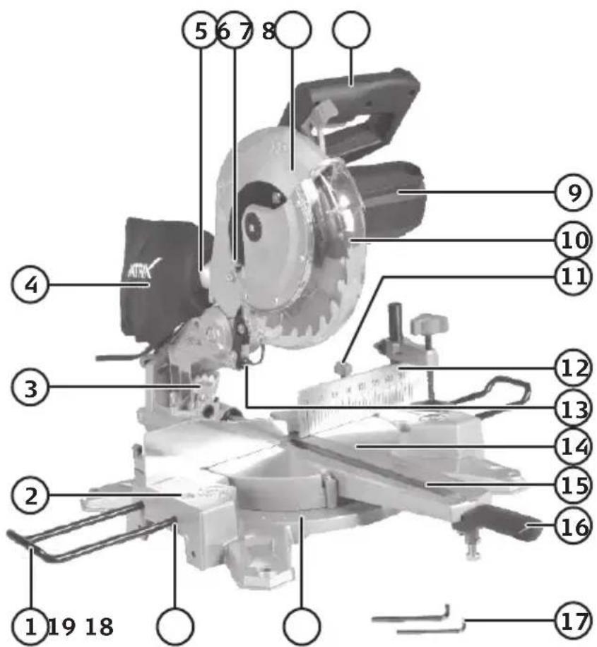
- Saw blade
- Spindle lock
- Saw blade guard release lever
- Saw head lock
- Workpiece clamp
- Lock for workpiece clamp (one on each side)
- Mounting holes (one in each corner)
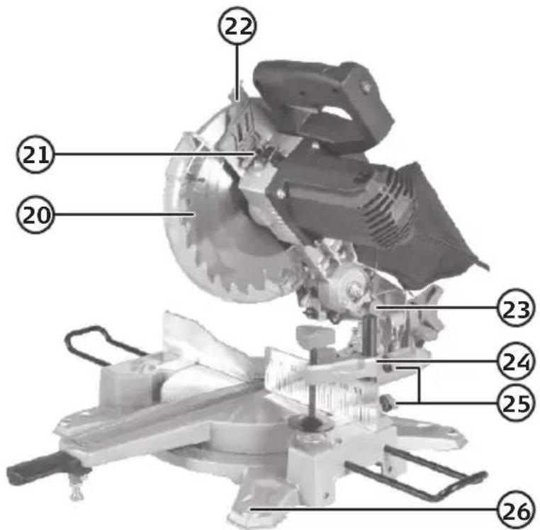
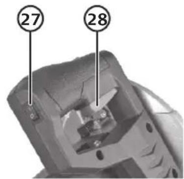
- [I/O] Laser line on/off switch
-
Saw blade power trigger
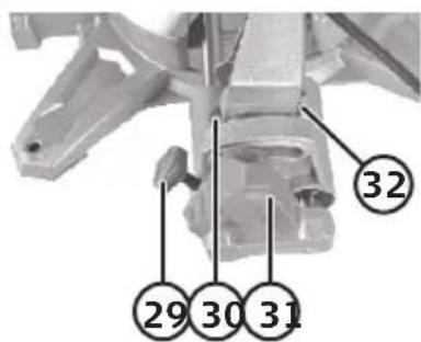
-
Slide rail locking knob
-
Bevel angle 0^ adjustment screw
-
Bevel angle locking knob
-
Bevel angle 45° adjustment screw
Before operating the machine
- The saw must be securely fastened to a workbench or stand.
- All guards and safety devices must be properly fitted.
- The saw blade must be able to turn freely in all work settings.
• Make sure that there are no foreign objects (nails, screws) in the workpiece to be sawn.
- Make sure that the saw blade is correctly fitted and that all moving parts run smoothly.
Fitting the included dust bag
Squeeze the spring clamp on the bag and slide the bag onto the dust extraction port (the port may also be used for connecting a dust extractor).
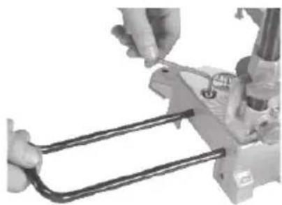
Fitting the side supports
Slide the rods of the side supports into the holes (19) and lock them in place using the locking screws (2).
natural_image
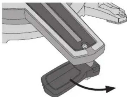
Close-up of hands using a tool to adjust a U-shaped metal component (no visible text or symbols)Installing the mitre angle lever
natural_image
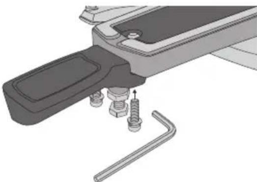
Mechanical component diagram showing a lever mechanism with an arrow indicating motion (no text or symbols present)- Swing out the lever so that it lines up with the slotted turntable insert.
natural_image
Mechanical assembly diagram showing a tool inserted into a bracket with a spring and wrench (no text or symbols)- Fasten the lever using the 2 provided set screws.
Operating instructions Cross-cutting
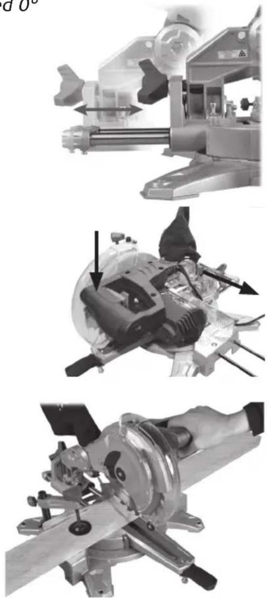
Cross-cutting with the saw blade angled 0^
When sawing narrow pieces of wood, the slide function is not required and the saw head can be locked in the rear position by tightening the slide rail locking knob (29). For sawing wide workpieces, first make sure that the slide rail lock is released so that the saw head can move before you begin sawing.
- Raise the saw head (7) to its upper position by first pressing the saw head down and then releasing the saw head lock (23). Note: Keep hold of the saw head when releasing the lock, otherwise it will spring up automatically.
-
Move the saw head backwards and fix it in this position with a slide lock if necessary (depending on the width of the workpiece).
-
Place the workpiece on the turntable (14) and hold it against the fence (12).
-
Secure the workpiece using the clamp (24) to prevent it from moving during the cutting process.
-
Switch the laser line on if necessary, using the switch (27).
-
Press in the power trigger (28) to start the motor, press in the blade guard release lever (22) and carefully lower the saw head and let the blade cut through the workpiece.
-
To switch the saw off, release the power trigger whilst still maintaining full control over the saw head. When the blade has stopped, the saw head can be moved back to its upper position.
Warning: The resetting springs in the machine automatically raise the saw head after cutting. Do not simply let go of the saw head after cutting, hold onto the handle and let it come up slowly.
natural_image
Three-panel technical illustration showing mechanical assembly steps: tool, blade, and workpiece (no text or symbols)Bevel cutting 0–45°
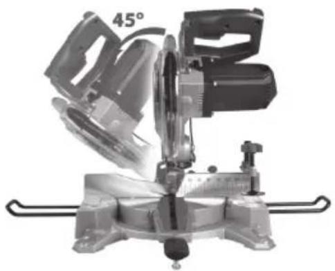
- Undo the locking knob (31) and tilt the blade to the desired angle with the help of the bevel angle scale (3).
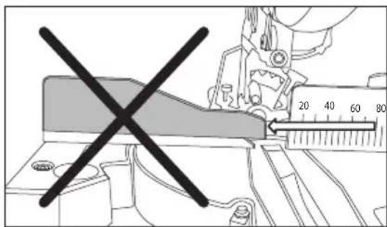
- Tighten the locking knob to lock the bevel angle. Adjust the fence (see below fig.).
- Cut as described above.
natural_image
Mechanical cutting machine with 45° angle annotation (no text or symbols on the device itself)
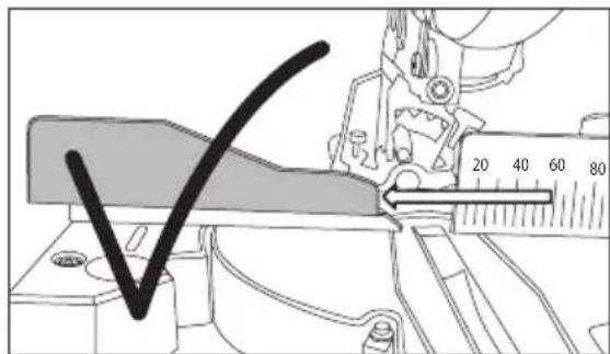
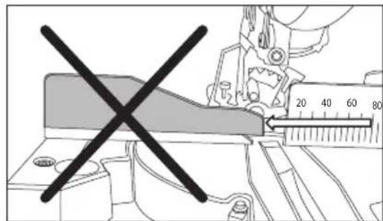
Important:
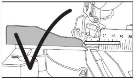
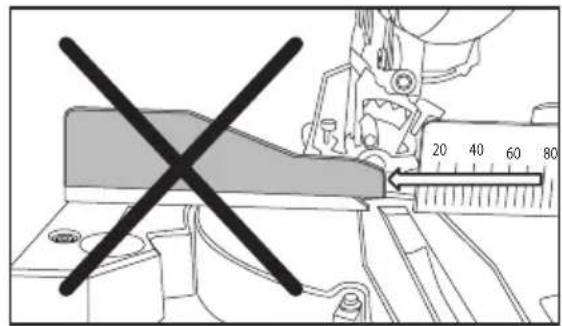
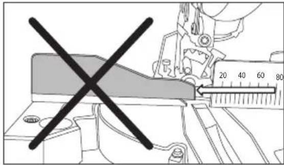
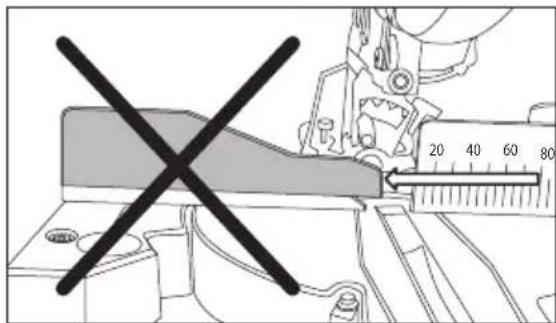
When sawing with the blade tilted at an angle, the fence must be moved out of the way to prevent it from obstructing the blade.
Fine-adjusting the 0^ and 45^ bevel angle stops
- Undo the locking knob (31) and angle the saw to 0°.
- Check the angle between the blade and the turntable using a 90° angle guide.
- Adjust the end stop using the adjuster screw (30) by slackening the nut and turning the screw. Lock the screw again afterwards by re-tightening the nut.
- To adjust the 45^ end stop, do as above but use the other adjuster screw (32) and a 45^ angle guide.
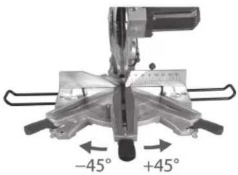
Mitre cutting -45°/0°/+45°
- Raise the saw head (7) to its upper position by releasing the lock (23).
- Undo the mitre angle lock (11) and set the saw to the desired mitre angle using the scale (18).
- Tighten the mitre angle lock and perform cutting operations as described above.
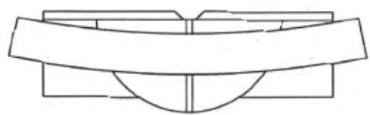
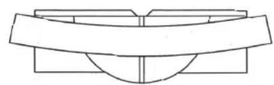
Sawing bowed workpieces
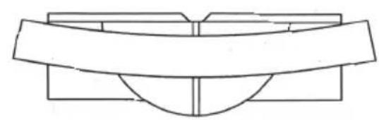
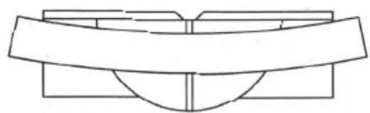
When sawing flat workpieces, it is advisable to check if the workpiece is bowed. If it is bowed, turn it as shown in the figure to prevent it from pinching the blade towards the end of the cut.
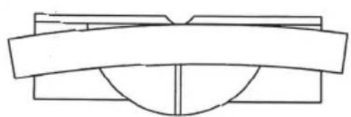
natural_image
Pure geometric diagram of a trapezoidal structure with no text, numbers, or symbolsCorrect Incorrect
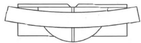
natural_image
Pure geometric diagram of a symmetrical structure with no text, numbers, or symbolsCare and maintenance
- Unplug the mains lead from the wall socket before cleaning and maintenance.
- Keep the saw clean and free of sawdust. Keep the ventilation openings of the motor free of dust and foreign particles.
- Remove accumulated sawdust using a damp cloth. Use only mild cleaning agents, never solvents or corrosive chemicals.
- If the saw is not to be used for an extended period, it should be unplugged and stored in a dry and dust-free location out of reach of children.
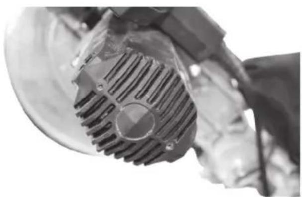
natural_image
Close-up of a mechanical component with a meshed circular feature, possibly a motor or gear assembly (no visible text or symbols)Dust bag
Squeeze together the ends of the spring clip, remove the bag and empty it as required.
Changing the blade
Note: Wear gloves whenever handling the blade, it is very sharp.
- Unplug the mains lead from the wall socket.
- Raise the saw head to its upper position by releasing the lock (23).
-
Undo the saw blade cover locking screw (6).
Note: The screw will not screw all the way out, just loosen it as far as it will go. -
Free the moving saw blade cover and raise it all the way up. Then lift the saw blade cover straight up so that the blade bolt is easily accessible.
-
Hold the blade cover while simultaneously pressing in the spindle lock button (21). Turn the saw blade until the spindle lock engages.
-
Keep the spindle lock pressed in and undo the blade bolt using the included hex key. Note: The blade bolt has a left-hand thread so you have to turn the bolt clockwise to undo it.
-
Remove the blade bolt, the washer and the outer flange.
-
Remove the blade from the inner flange.
-
Fit the new blade in the reverse order. Swing the blade guard back into place and tighten the screw which you loosened during step 3 above.
-
Clean the saw blade flanges and bolt thoroughly before fitting the new blade. The direction of rotation of the blade must be the same as the 3 arrows on the safety guard (7).
-
Make sure the spindle lock is off.
-
Before using the saw again, make sure that all safety devices are in good working order.
Warning: Every time you change the blade, make sure that it spins freely in all angle settings.
Warning: Remove the hex key and release the spindle lock before switching the machine on.
Note: These screws must not be removed.
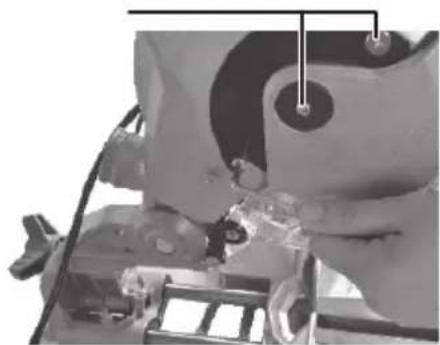
natural_image
Close-up mechanical assembly showing a component with no visible text or symbols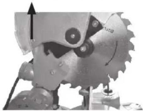
natural_image
Close-up of a mechanical gear with teeth and a directional arrow indicating motion (no text or symbols)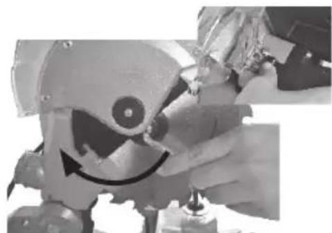
natural_image
Close-up of a robotic arm with a curved motion arrow, no visible text or symbolsInspecting and replacing carbon brushes
Warning: Unplug the machine before inspecting the carbon brushes.
The life expectancy of the brushes depends on how hard the motor has been run. If the saw is new or if the brushes have just been replaced, the condition of the brushes should be checked after 50 hours of operation. They should then be checked after every 10 hours operation until they need to be replaced again.
Check the carbon brushes as follows:
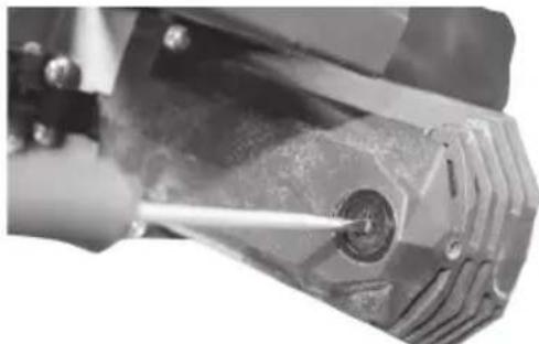
- Remove the plugs, one on each side of the motor.
- The carbon brushes are located under the plugs. Pull the brushes out of their holders (it might be necessary to pry out the holders if they don't spring out automatically when the plugs are removed).
- Check the length of the carbon brushes; they should be at least 6 mm in length.
- If either of the brushes is shorter than 6 mm or the spring is damaged, they must both be changed.
natural_image
Close-up of a precision tool interacting with a mechanical component (no visible text or symbols)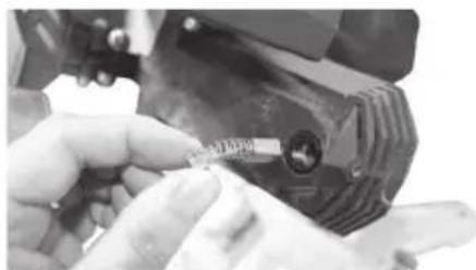
natural_image
Close-up of hands using a tool to adjust or install a small component (no visible text or symbols)Responsible disposal
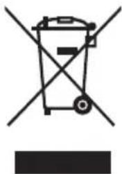
This symbol indicates that this product should not be disposed of with general household waste. This applies throughout the entire EU. In order to prevent any harm to the environment or health hazards caused by incorrect waste disposal, the product must be handed in for recycling so that the material can be disposed of in a responsible manner. When recycling your product, take it to your local collection facility or contact the place of purchase. They will ensure that the product is disposed of in an environmentally sound manner.
natural_image
Symbol of a trash bin crossed with a diagonal line, no text or labels presentSpecifications
Mains power supply 230 V AC, 50 Hz
Rated power 1450 W
No-load speed 5000 rpm
Saw blade TCT ∅ 210 × ∅ 30 mm
Number of teeth 24
Saw blade bevel tilt 0–45°
Variable mitre angle -45^/0^/+45^
Max workpiece size at
0° mitre and 0° bevel 210 × 60 mm
Max workpiece size at
0° mitre and 45° bevel 210 × 34 mm
Max workpiece size at
45° mitre and 0° bevel 148 × 60 mm
Max workpiece size at
45° mitre and 45° bevel 148 × 34 mm
Noise emission LpA = 97.3 dB(A), K = 3 dB(A)
LwA = 110.3 dB(A), K = 3 dB(A)
Vibration level 3.540 m/s²
Size 33 × 46 × 48 cm
Weight 8.8 kg
Laser class 2 in accordance with EN 60825-1
P = < 1 mW, = 650 nm
Kap- och geringssåg
Art.nr 18-3602, 41-1072, Modell M1YL-4DF-216JA
natural_image
Close-up of hands using a tool to adjust a metal component (no visible text or symbols)natural_image
Mechanical component diagram showing a lever mechanism with a curved arrow indicating motion (no text or symbols present)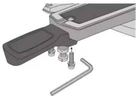
natural_image
Mechanical assembly diagram showing a tool with bolts and a wrench, no text or symbols presentnatural_image
Mechanical assembly diagram showing a rotating shaft and housing components (no visible text or symbols)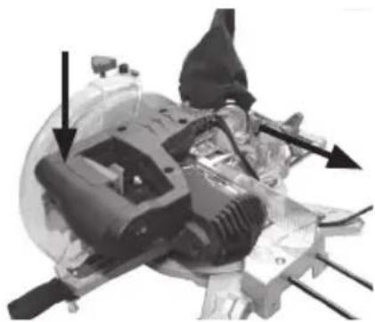
natural_image
Mechanical assembly diagram showing internal components and directional arrows (no text or labels)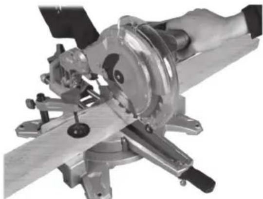
natural_image
Close-up of a hand operating a metal cutting machine with a workpiece (no visible text or symbols)natural_image
Industrial cutting machine with a 45° angle indicator, no visible text or symbols on the machinery itself.
Viktigt:
natural_image
Pure geometric diagram of a trapezoidal structure with no text, numbers, or symbolsRätt Fel
natural_image
Pure geometric diagram of a symmetrical structure with no text, numbers, or symbolsnatural_image
Close-up of a mechanical gear assembly with meshing and mounting holes (no visible text or symbols)Spånpåse
natural_image
Close-up of a precision tool interacting with a mechanical component (no visible text or symbols)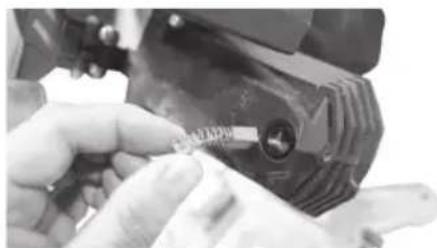
natural_image
Close-up of a hand holding a small object with a ruler, next to a mechanical component (no visible text or symbols)Avfallshantering
natural_image
Symbol of a trash bin crossed with no text or labels, accompanied by a black rectangle below (no readable text or symbols)Specifikationer
natural_image
Close-up of hands using a tool to adjust a metal component (no visible text or symbols)natural_image
Mechanical assembly diagram showing two components with arrows indicating motion (no text or symbols)natural_image
Industrial machine with mechanical components and a directional arrow indicating motion (no visible text or symbols)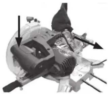
natural_image
Mechanical assembly diagram showing internal components and directional arrows (no text or labels)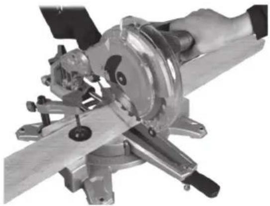
natural_image
Close-up of a hand operating a mechanical workpiece with a cutting tool and wooden base (no visible text or symbols)natural_image
Industrial cutting machine with 45° angle annotation (no visible text or symbols on the machine itself)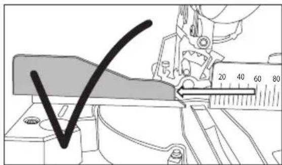
natural_image
Pure geometric diagram of a symmetrical structure with no text, numbers, or symbolsRiktig Galt
natural_image
Pure technical line drawing of a symmetrical mechanical component with no text or symbolsnatural_image
Close-up of a mechanical gear assembly with meshing and mounting holes (no visible text or symbols)Sponpose
natural_image
Close-up of a mechanical component with a pointed tool inserted, showing internal features and no visible text or symbols.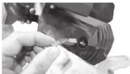
natural_image
Close-up of a hand adjusting a mechanical component with a small label (no visible text or symbols)Avfallshåndtering
natural_image
Symbol of a trash bin crossed with no text or labels, representing environmental restriction (no text present)Spesifikasjoner
Nettilkobling 230 V AC, 50 Hz
Effekt 1450 W
Turtall ubelastet 5000 o/min.
Sagblad m. hardmetalltenner ∅ 210/30 mm
Antall tenner 24 stk.
natural_image
Close-up of hands using a pliers to handle a black metal object (no visible text or symbols)natural_image
Mechanical assembly diagram showing a lever mechanism with a curved arrow indicating motion (no text or symbols present)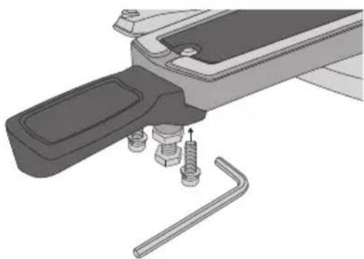
natural_image
Mechanical assembly diagram showing a tool with bolts and a wrench, no text or symbols presentnatural_image
Industrial machinery assembly with rotating shaft and flange components (no visible text or symbols)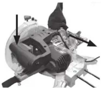
natural_image
Mechanical assembly diagram showing internal components with arrows indicating motion or force directions (no text or symbols present)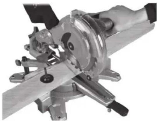
natural_image
Close-up of a hand operating a metal cutting machine with a workpiece (no visible text or symbols)natural_image
Industrial cutting machine with 45° angle annotation (no visible text or symbols on the machine itself)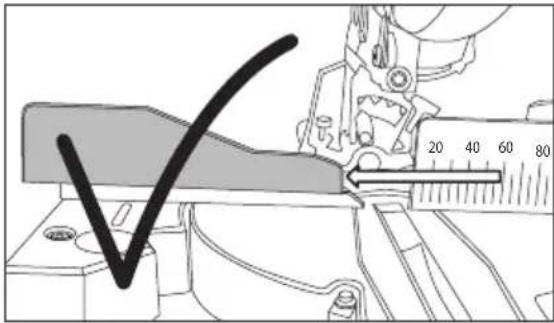
natural_image
Pure geometric diagram of a trapezoidal shape with no text, numbers, or symbolsOikein Väärin
natural_image
Pure technical line drawing of a symmetrical mechanical component (no text or symbols)natural_image
Close-up of a mechanical gear assembly with visible teeth and mounting brackets (no text or symbols)Purupussi
natural_image
Mechanical assembly diagram showing components like gears and a housing (no visible text or labels)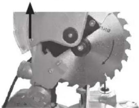
natural_image
Close-up of a mechanical gear with teeth and a rotating shaft (no visible text or symbols)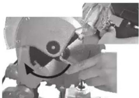
natural_image
Close-up of a robotic arm with a smiling face and motion arrow, partially held by a hand (no visible text or symbols)natural_image
Two-panel black-and-white photo showing a hand using a tool to adjust or install a mechanical component, no visible text or symbols.Kierrättäminen
natural_image
Symbol of a trash bin crossed with no text or numbers, representing waste sorting or disposal (no text present)Tekniset tiedot
natural_image
Close-up of hands using a tool to lift a metal rod (no text or symbols visible)natural_image
Mechanical assembly diagram showing two components with arrows indicating motion (no text or symbols)natural_image
Mechanical assembly diagram showing a rotating shaft and housing components (no visible text or symbols)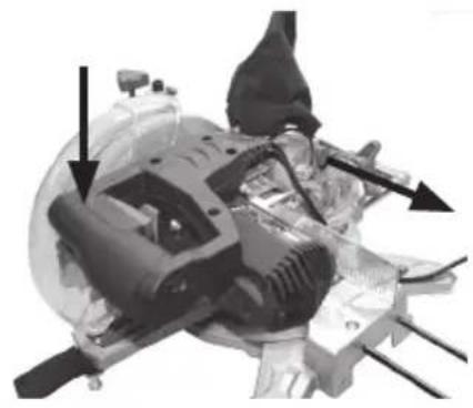
natural_image
Mechanical assembly diagram showing internal components with arrows indicating motion direction (no text or labels)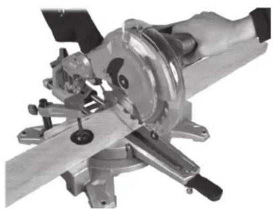
natural_image
Close-up of a hand operating a metal cutting machine with a workpiece (no visible text or symbols)natural_image
Industrial cutting machine with 45° angle annotation, no visible text or symbols on the machinery itself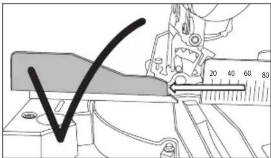
natural_image
Pure geometric diagram of a symmetrical structure with no text, numbers, or symbolsRichtig Falsch
natural_image
Pure technical line drawing of a symmetrical mechanical component with no text or symbolsPflege und Wartung
natural_image
Close-up of a mechanical gear assembly with visible teeth and central hub (no text or symbols)Spanbeutel
natural_image
Close-up of a mechanical component with a tool inserted, showing a circular feature and threaded shaft (no text or symbols visible)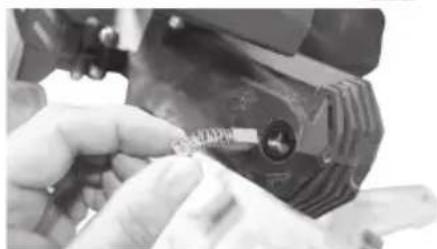
natural_image
Close-up of hands using a tool to adjust or install a small component (no visible text or symbols)natural_image
Symbol of a trash bin crossed out by two crossed lines, with no text or labels present.Technische Daten
Declaration of Conformity
Machinery Directive 2006/42/EC
EN 61029-1:2009+A11
EN 61029-2-9:2012+A11
EN 60825-1: 2014
EMC Directive 2014/30/EU
EN 55014-1:2006+A1+A2
EN 55014-2:2015
EN 61000-3-2:2014
EN 61000-3-3:2013
EC TYPE CERTIFICATE, NO. AM 50315557 0001
ISSUED BY THE FOLLOWING NOTIFIED BODY:
UTFÄRDATS AV FÖLJANDE ANMÄLDA ORGAN:
UTSTEDT AV F∅LGENDE TEKNISK KONTROLLORGAN:
MYÖNTÄNYT SEURAAVA ILMOITETTU LAITOS:
Product Compliance Manager
Insjön, Sweden, 2019-05-27
CLAS OHLSON AB, SE-793 85 INSJÖN, SWEDEN
Sverige
Postal 10 - 13 Market Place
Kingston upon Thames
Surrey
KT1 1JZ
Deutschland
Kundenservice Hotline: 040 2999 78111
E-Mail: kundenservice@clasohlson.de
Homepage
www.clasohlson.de

- Viktig information:
- Safety
- Warning!
- Additional safety rules for compound mitre saws
- In spite of the application of the relevant safety rules and the implementation of safety devices, certain residual risks cannot be avoided. The following hazards are inherent to the use of mitre saws:
- Safety symbol guide
- Product description
- Before operating the machine
- Fitting the included dust bag
- Fitting the side supports
- Installing the mitre angle lever
- Operating instructions Cross-cutting
- Bevel cutting 0–45°
- Important:
- Fine-adjusting the 0° and 45° bevel angle stops
- Mitre cutting -45°/0°/+45°
- Sawing bowed workpieces
- Care and maintenance
- Dust bag
- Changing the blade
- Inspecting and replacing carbon brushes
- Responsible disposal
- Specifications
- Kap- och geringssåg
- Viktigt:
- Spånpåse
- Avfallshantering
- Specifikationer
- Sponpose
- Avfallshåndtering
- Spesifikasjoner
- Purupussi
- Kierrättäminen
- Tekniset tiedot
- Pflege und Wartung
- Spanbeutel
- Technische Daten
- Declaration of Conformity
- Sverige
- Deutschland
Brand : Cocraft
Model : HMS 210-L
Category : Saw