HBD500 - Mill Cocraft - Free user manual and instructions
Find the device manual for free HBD500 Cocraft in PDF.


| Product Type | Belt and Disc Sander |
| Brand | Cocraft |
| Model | HBD500 |
| Rated Voltage | 230 V ~ 50 Hz |
| Rated Power | 500 W |
| Disc No-Load Speed | 2850 rpm |
| Belt No-Load Speed | 7.35 m/s |
| Sanding Disc Diameter | 150 mm |
| Sanding Belt Size | 100 x 915 mm |
| Work Table Size | 160 x 225 mm |
| Work Table Tilt | 0 to 45° |
| Belt Assembly Tilt | 0 to 90° |
| Sound Pressure Level (LpA) | 79.9 dB(A) (K=3 dB(A)) |
| Sound Power Level (LwA) | 91.1 dB(A) (K=3 dB(A)) |
| Weight | 19 kg |
| Switch Type | No-volt release switch (push button) |
| Dust Extraction Port | Yes, with dust bag recommended |
| Belt Tracking Adjustment | Knob on side |
| Base Mounting | Through holes in baseplate |
| Safety Features | Safety guard, no-volt release switch, emergency stop button |
Frequently Asked Questions - HBD500 Cocraft
User questions about HBD500 Cocraft
0 question about this device. Answer the ones you know or ask your own.
Ask a new question about this device
Download the instructions for your Mill in PDF format for free! Find your manual HBD500 - Cocraft and take your electronic device back in hand. On this page are published all the documents necessary for the use of your device. HBD500 by Cocraft.
USER MANUAL HBD500 Cocraft
Read the entire instruction manual carefully and make sure that you fully understand it before you use the equipment. Keep the manual for future reference.
Viktig information:
natural_image
Cocraft HBD 500 industrial machine with red circular component and control buttons (no readable text or symbols on main subject)Art.no Model
18-3558
40-8831
MM491GL
MM491GL
Ver. 20170207
Original instructions
Bruksanvisning i original
Originalbruksanvisning
Belt and Disc Sander
Art.no 18-3558 Model MM491GL
40-8831 MM491GL
Please read the entire instruction manual before using the product and save it for future reference. We reserve the right for any errors in text or images and any necessary changes made to technical data. If you have any questions regarding technical problems please contact our Customer Services.
Contents
- Safety......4
1.1 General safety instructions for your safety and the safety of others...4
1.2 Specific safety regulations for bench sanders ....5
1.3 Key to warning symbols....6
-
Product description......6
-
Assembly and preparations......8
3.1 Replacing the sanding disc....8
3.2 Replacing the sanding belt....9
3.3 Mounting the work table for use with the sanding disc....10
3.4 Mounting the work table for use with the sanding belt....10
3.5 Mounting the backstop....11
3.6 Sanding belt tracking....11
3.7 Using the sanding belt at different angles....11
3.8 Power switch operation....12
3.9 Placement....12
3.10 Adjusting and changing the drive belt 12
- Operating instructions ....13
4.1 Bevel sanding using the work table 13
4.2 Surface sanding on the sanding belt 13
4.3 Sanding the ends of long workpieces ....13
4.4 Sanding curved surfaces....13
-
Useful tips ......14
-
Troubleshooting ....15
-
Responsible disposal ....15
-
Specifications....15
1. Safety
1.1 General safety instructions for your safety and the safety of others
- Keep the working area tidy. Cluttered surfaces and benches invite accidents.
- Do not use the machine in dangerous environments. The machine should not be used on moist or wet surfaces or in rain. Make sure that the work area is well lit. When working in dusty atmospheres, make sure that the air is adequately circulated. Do not operate power tools in explosive atmospheres, such as in the presence of flammable liquids, gases or dust.
- Avoid electric shocks. Avoid body contact with earthed or grounded surfaces such as pipes, radiators, ranges and refrigerators when using power tools.
- Keep children and bystanders away. Keep children and visitors at a safe distance from electrical machinery/tools and electric cables in the workplace.
- Store power tools out of the reach of children. When not in use, power tools should be stored locked away in a safe place, away from children.
- Do not force the machine. The correct feed rate makes the work better and safer.
- Use the correct tool for the job. Do not force a tool to perform a task that it was not designed for.
- Wear suitable attire. Do not wear any loose-fitting clothing, gloves, necklaces, bracelets or other jewellery that can get caught in moving parts. Non-slip footwear is recommended. Wear a hairnet or similar if you have long hair.
- Always wear safety glasses. Normal glasses are not tough enough to withstand impacts. Use a dust mask or dust filter when working in dusty environments.
- Connect dust extraction equipment. If the machine is equipped with dust extraction equipment, ensure that it is connected and used properly. Make sure to empty the dust bag regularly.
- Do not abuse the mains lead. Do not carry the machine by its mains lead. Do not use the mains lead to pull or unplug the power tool, pull the plug out instead. Make sure that the mains lead does not come into contact with heat, oil, or sharp edges.
- Secure the workpiece firmly. Where possible, use clamps or a vice. You can then operate the tool using two hands. This is much safer than holding the workpiece in one hand.
- Do not overreach. Make sure that you stand steady and balanced all times.
- Look after you tools. Keep blades sharp and clean for the best and safest performance.
- Follow the manuals recommendations regarding lubrication and replacement of accessories. If it is damaged it should be replaced by a qualified service technician. Inspect all leads and cables regularly to check for any damage. Make sure that the machine's handles and controls are clean, dry and free from oil and grease.
- Turn the power off. Pull out the plug and push in the emergency stop button before servicing or changing any blades, drill bits, cutters or sanding discs.
-
Remove all spanners and repair tools. Make a habit of checking to make sure that the machine is free of all spanners and tools before turning the power on.
-
Avoid accidental starts. Do not walk around with your finger on the trigger of a power tool if it is plugged in. Make sure that the power switch is set to [0] before plugging in any power tool.
- Use the correct extension leads. If you use extension leads outdoors, only use those designed for outdoor use. Only use extension leads with adequate wire core area and roll out the whole lead.
- Use common sense and be careful. Think carefully before carrying out every action, so that it is carried out safely. Never operate machines/power tools when you are tired or under the influence of medicine.
- Inspect the tool for damage. Before starting the tool, make sure that the guards and other parts are undamaged and working properly, that moving parts can rotate freely and are correctly aligned, that no moving parts can get caught and that there is no fault or defect that could affect the performance of the machine. A safety guard or any other part that is damaged should be repaired by a tradesman or replaced. Damaged power leads and switches must always be replaced by a tradesman. Never operate a tool if you cannot stop or start the tool comfortably.
- Use only recommended accessories. The use of non-recommended accessories can cause accidents and personal injury.
- Should only be repaired by a qualified technician. This tool conforms to current safety requirements. Repairs to the tool should only be carried out by a tradesman using original spares; otherwise the tool could cause accidents and personal injury.
- Use a Residual Current Device on all 230 V power tools. This can help minimise the risk of an electric shock if an earth fault or short circuit occurs. The product must not be modified or used for any other purpose than that for which it has been designed. Regularly check that all screws and nuts are securely tightened.
1.2 Specific safety regulations for bench sanders
- Place the machine on a stable, level surface with plenty of room for manoeuvre.
- Think about how you are going to hold the workpiece during the entire sanding operation. Be wary of kickbacks and injuries. The workpiece could catch in the sanding belt or disc and be ripped from your grasp.
- When using the sanding disc, always hold the workpiece against the side of the disc moving downwards towards the table. If you sand against the upward side the workpiece can easily be ripped from your grasp.
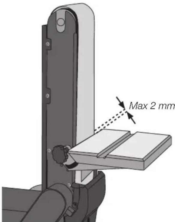
- The distance between the belt/disc and work rest must never exceed 2 mm.
- To prevent the risk of fire; keep the machine free of sander dust. Sparks produced when sanding metal can start fires. Prevent this by:
- Disconnecting any dust extractor suction hose that might be attached.
- First blowing off any dust particles on or in the machine.
- Removing any particles of metal before sanding wood again.
- Using the sander in a dry place, indoors and out of the rain. Make sure that the work area is well illuminated.
- Position the sander in such a way neither the user nor any observer need stand in line with the sanding belt or disc.
- Remove everything from the side table except the workpiece and the mitre guide.
- Avoid placing your hands in such a way that an accidental slip might cause a finger or hand to come into contact with the abrasive surface. Keep your fingers well away from the opening to the dust extractor.
- Keep your face and as much of your body as possible out of range of possible kickbacks.
1.3 Key to warning symbols

natural_image
Icon of a person reading a book inside a circle (no text or symbols)Warning: Read the entire instruction manual before use.

natural_image
Simple line drawing of a person wearing glasses and a phone receiver, enclosed in a circle (no text or symbols)Warning: Always wear safety glasses. Use of respiratory and hearing protection is recommended.
2. Product description
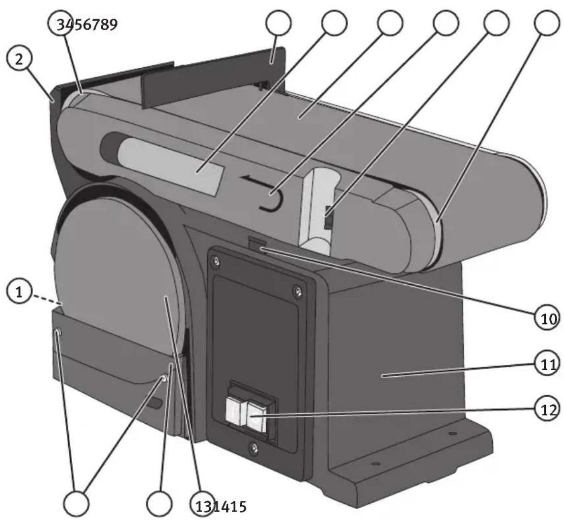
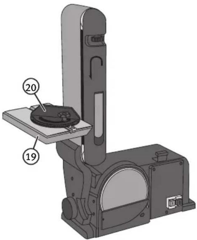
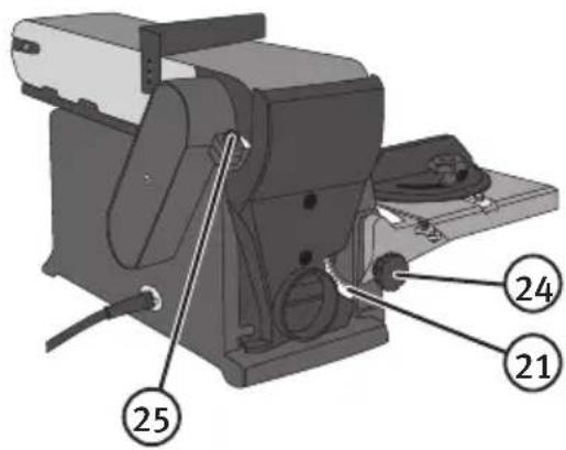
- Dust extractor port
- Safety guard
- Drive roller
- Backstop
- Belt tension release lever
- Belt sander assembly
- Rotation arrow
- Belt tracking knob
- Idler roller
- Rubber support
- Base with fastening holes
- [I] [O] No-volt-release on/off switch
- Sanding disc
- Disc guard
- Disc guard screws
- Backstop socket head cap screws
- Drive belt cover
- Drive belt tensioning hole
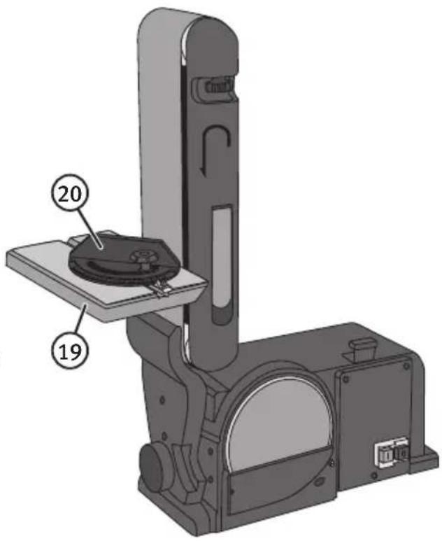
- Work table with bracket
- Mitre gauge
- Bevel gauge for work table
- Sanding belt guard
- Sanding belt guard screws
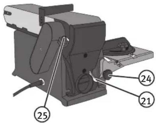
- Work table locking knob
- Sanding belt locking bolt
- Cross head drive belt tensioning screws (under the belt cover)
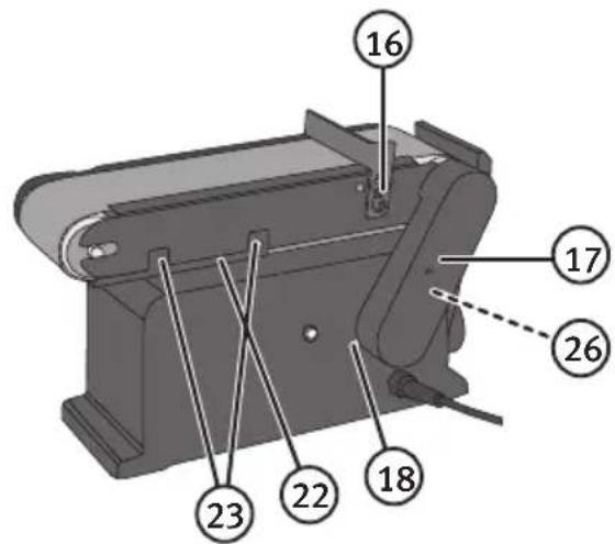
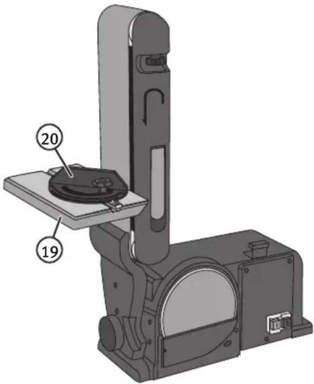
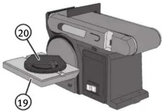
The bench sander is partly disassembled to protect it during transport.
Check that none of the following parts is missing before throwing the box away:
- Bench sander
- Backstop
- Tools
- Adjustable work table
- Mitre gauge
• Instruction manual
3. Assembly and preparations
Warning: Make sure that the plug is removed from the power point before assembling or servicing/adjusting the machine. The sanding belt and sanding disc are ready fitted.
3.1 Replacing the sanding disc
- Unplug the sander.
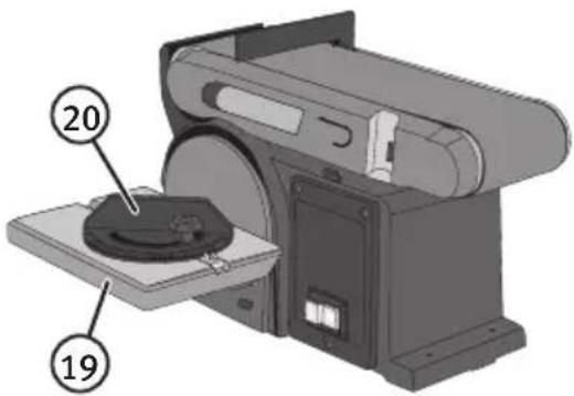
- First, remove the work table (19) if it is fitted.
- Loosen the 2 retaining screws (15) which hold the shield over the sanding disc(14). The screws should not be removed, just loosened a turn. Lift up the shield somewhat and remove it.
- Pull off the used disc and clean the disc plate of any old adhesive residue.
- Peel the protective film off the new sanding disc paper.
- Align the new disc paper on the disc plate, making sure that it is centred. Press the sanding disc paper firmly onto the disc plate.
- Screw the disc guard back over the sanding disc.
natural_image
Technical line drawing of hands operating a mechanical device with a tool (no text or symbols visible)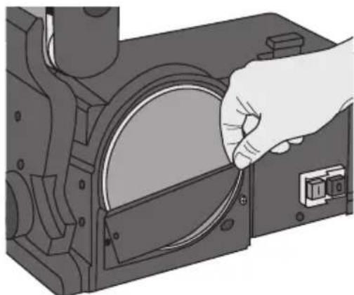
natural_image
Illustration of a hand inserting a circular component into a mechanical housing (no text or symbols visible)3.2 Replacing the sanding belt
- Unplug the sander.
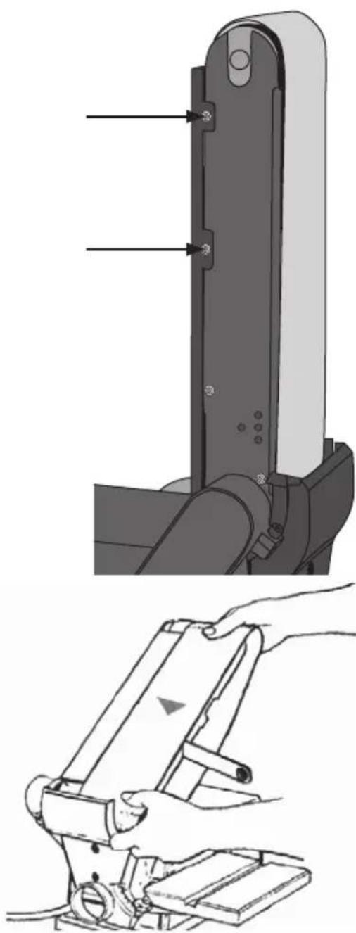
- Tilt the sanding belt assembly (6) so that it is vertical.
-
Loosen the 2 retaining screws (23) which hold the shield (22) over the belt sander. The screws should not be removed, just loosened a turn. Lift up the shield somewhat and remove it.
-
Release the belt tension lever (5) to free the idler roller (9) so that the sanding belt comes free. Warning: The tension release lever is spring-loaded, be careful when moving it.
-
Remove the old sanding belt from the rollers.
-
Fit the sanding belt the right way round. The new sanding belt will have an arrow on indicating the direction of rotation. The sanding belt must rotate in the direction of the arrow. There is also an arrow on the side of the sanding belt assembly (7). The arrows on the machine and on the sanding belt must point the same way. Make sure that the sanding belt is centred on both the rollers.
-
Slide the belt tension release lever (5) back to re-tension the belt.
-
Refit the sanding belt guard (22). Tighten the screws (23) on the side of the sanding belt assembly. Note: The sanding belt guard is held in place by the screws (23) and by 2 screws on the opposite side of the assembly into which the slots on the guard slide.
-
Switch the machine on and check that the belt does not tend to slide off the drive roller or idler roller. Adjust the tracking if necessary.
natural_image
Technical illustration of a mechanical device with labeled parts, showing top and side views (no text or symbols)3.3 Mounting the work table for use with the sanding disc
- Unplug the sander.
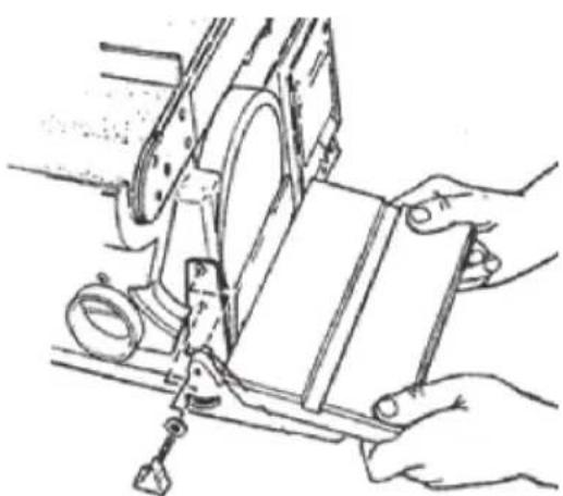
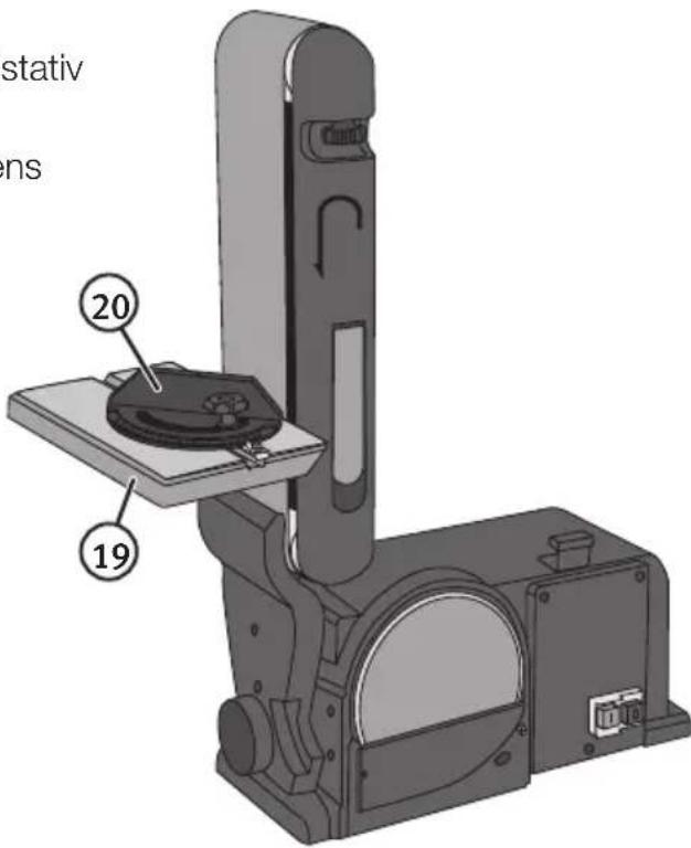
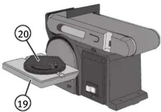
- Insert the work table guide pin (on top of the bracket) into the hole in the housing of the sander.
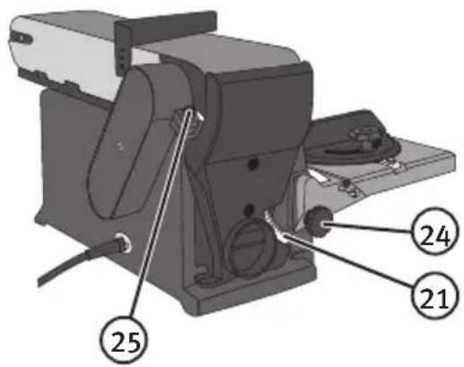
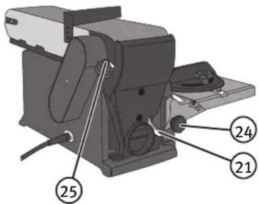
- Attach the work table to the base using the locking knob (24) (put a washer behind the locking knob).
- To adjust the gap between the table and the sanding disc, undo the three nuts on the bottom of the table. Adjust the work table so that the gap between the table and sanding disc is no more than 1–2 mm. Tighten the three nuts on the bottom of the table and tighten the
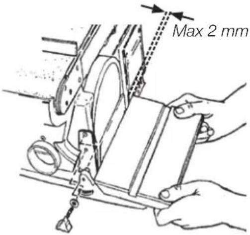
Warning: The gap between the sanding disc and table must be no more than 1–2 mm, otherwise there is the possibility of fingers becoming trapped in the gap.
3.4 Mounting the work table for use with the sanding belt
- Unplug the sander.
- First, remove the backstop (4) if it is fitted.
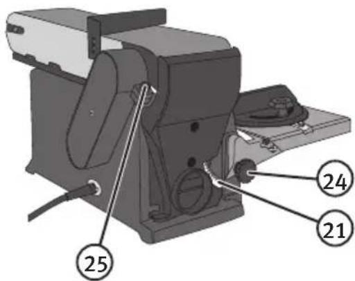
- Undo the locking bolt (25), raise the sanding belt assembly (6) and then tighten the locking bolt.
- Insert the work table guide pin (on top of the bracket) into the hole in the housing.
- Screw in the work table locking knob (24).
- To adjust the gap between the table and the sanding belt, undo the three nuts on the bottom of the table. Adjust the work table so that the gap between the table and sanding belt is no more than 1–2 mm. Tighten the nuts and the locking knob.
Warning: The distance between the sanding belt and table must be no more than 1–2 mm, otherwise there is the possibility of fingers becoming trapped in the gap.
3.5 Mounting the backstop
- Unplug the sander.
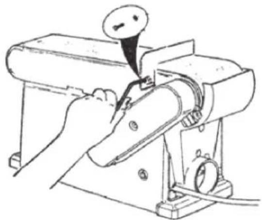
- Place the backstop (4) over the holes in the side of the sanding belt assembly.
- Attach the back stop by screwing in 2 socket head cap screws (16) fitted with flat washers.
- Adjust the backstop so that the gap between it and the belt is no more than 1–2 mm. Tighten the screws.
natural_image
Line drawing of a sewing machine with a needle inserted, no text or symbols present3.6 Sanding belt tracking
- Plug the sander into a wall socket.
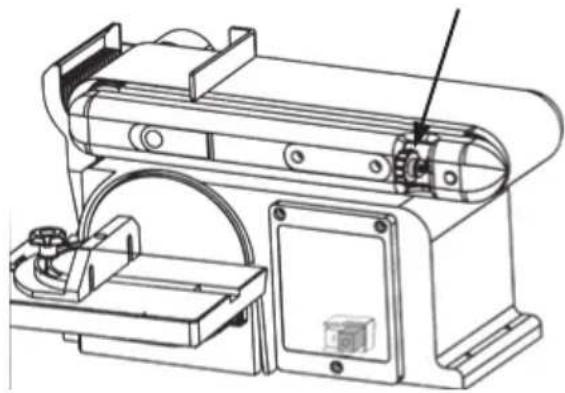
- Turn on the motor and turn it off straight away. Watch how the belt rotates on the rollers and note whether it is centred or whether it is pulling to one side. If the belt is centred on both the rollers it does not need adjusting, but if not:
- If the belt moves towards the sanding disc – turn the tracking knob (8) clockwise 14 turn (looking from the drive roller).
natural_image
Technical line drawing of a mechanical device with mounting bracket and control panel (no text or symbols)- If the belt moves away from the sanding disc – turn the tracking knob (8) anticlockwise 14 turn (looking from the drive roller).
- Turn on the motor and turn it off straight away, to check the tracking again. Repeat the above tracking procedure until the belt is centred on both of the rollers.
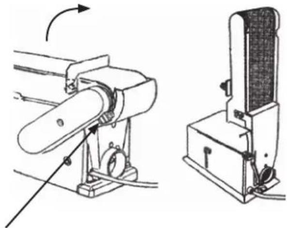
3.7 Using the sanding belt at different angles
- Unplug the sander.
- Undo the sanding belt locking bolt (25), raise the belt assembly (6) to the desired angle and then tighten the locking bolt.
natural_image
Technical line drawing of a mechanical device with rotating arm and side-mounted base (no text or symbols)3.8 Power switch operation
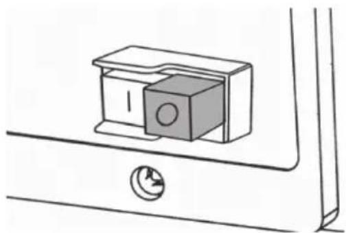
The sander is fitted with a combined power/no-volt release switch (12).
- Push the green button [I] to start the motor.
- Push the red button [0] to turn the motor off.
The no-volt release switch prevents the motor from automatically starting again following a power cut. If the no-volt release switch has been triggered, the machine can only be restarted by pushing in the green button.
natural_image
Simple line drawing of a cabinet with a circular knob and handle, mounted on a bracket (no text or symbols)3.9 Placement
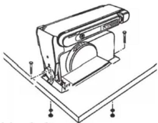
Position the machine on an appropriately high bench and secure it with bolts through the holes in the baseplate. Use spring washers or lock nuts. Bear in mind that there must even be enough room around the sander for working on large workpieces.
natural_image
Technical line drawing of a mechanical device with mounting brackets and a central circular component (no text or symbols)3.10 Adjusting and changing the drive belt
-
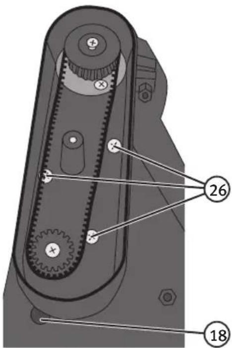
Remove the retaining screw in the drive belt cover (17).
-
Remove the cover.
-
Undo the three cross head screws (26) enough for you to be able to move the upper drive roller enough fit the drive belt.
-
Tighten the three cross head screws a little. Set the belt tension by inserting a normal flat head screwdriver in the tensioning hole (18) under the belt cover. Push the screwdriver upwards to increase the belt tension.
-
Tighten the cross head screws without altering the tension.
-
Test the belt tension by squeezing the two sides of the belt together in the middle. It should be possible to move the belt 6–7 mm. A drive belt which is too taut can increase the noise emission and overload the motor and bearings. If the drive belt is too slack, the belt can slip or wear out too quickly.
-
Screw the belt cover back on.
4. Operating instructions
4.1 Bevel sanding using the work table
The work table can be tilted to an angle of 0–45°.
- Undo the locking knob (25) and tilt the work table to the desired angle.
- Tighten the locking knob. The supplied mitre gauge (20) should be used when sanding small workpieces on the sanding disc.
a) Hold the mitre gauge against one side of the workpiece.
b) Always hold the workpiece against the left half of the sanding disc.
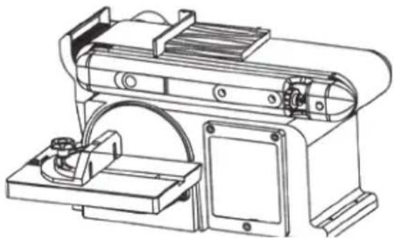
4.2 Surface sanding on the sanding belt
The belt can be used either horizontally or vertically. The backstop (4) can also be used with the belt in either position.
Surface sanding is best done horizontally.
- Hold the workpiece firmly in both hands, making sure that your hands do not touch the belt.
- Keep one end of the workpiece firmly pressed against the backstop.
- Move the workpiece slowly back and forth sideways across the sanding belt. Be careful when sanding thin workpieces.
- Do not exert too much pressure; a light touch is all that is required. Remove a little material on each pass.
Note: The backstop should be removed for sanding long workpieces.
natural_image
Technical line drawing of a mechanical device with mounting bracket and housing (no text or symbols)4.3 Sanding the ends of long workpieces
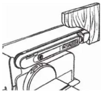
Use the work table (19) as a support when sanding the ends of long workpieces.
4.4 Sanding curved surfaces
Always sand inside radius curves on the idler roller (9).
Warning: Never attempt to sand the ends of a workpiece on the idler roller as the workpiece can kickback and cause an injury.
natural_image
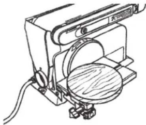
Technical line drawing of a mechanical device with wooden components and a circular base (no text or symbols)Always sand outside radius curves on the left half of the sanding disc.
Warning: Never attempt to sand a workpiece on the right half of the sanding disc as the workpiece can kickback and cause an injury.
natural_image
Technical line drawing of a mechanical device with a magnified circular component (no text or symbols)5. Useful tips
- The sanding belt is suitable for working on objects made of wood or plastic.
Surface finishing should be carried out with a firm grip on the workpiece but without applying too much pressure onto the sanding belt. Move the workpiece back and forwards over the belt to avoid grooves forming on the workpiece and so that the belt wears evenly. - Use the backstop to support the workpiece. If the workpiece is longer than the sanding belt, the backstop can be removed to maximise the working surface.
- The sanding disc is perfect for forming and rounding pieces of wood.
- The quality of the finish depends entirely on the grit size of the sandpaper and how the workpiece is handled. The best result will be achieved by first sanding with coarse grade sandpaper and then continuing with a finer grade.
- It is often more practical to use the belt sander in the vertical position. The workpiece can then often be supported on the workbench.
- The machine is very efficient and designed for quick work removal, which means that you need to be careful not to “over-sand”. Inspect the workpiece often during the sanding operation to make sure that you do not remove more material than intended.
- Wood should always be sanded in the direction of the grain. Sanding against the grain can produce grooves in the wood and deep scratches when finishing. Do not apply too much force; let the machine do the work. The results will be much better.
- To achieve the best finish on softwoods such as pine and spruce, you should apply a thin layer of diluted shellac onto the surface of the wood before the final sanding. When the layer of shellac is removed it takes with it the fine nap of wood flakes that form on the surface of softwoods, thus leaving a much smoother finish.
- The careful dressing of straight or bevelled edges is best performed using the mitre gauge.
6. Troubleshooting
| Problem Possible cause | Action | |
| The motor does not start. | Defective switch or power supply. | Replace the defective part before commencing work. |
| The machine slows down when sanding. | Too much pressure applied to workpiece. | Apply less pressure. |
| The sanding belt keeps coming off. | Incorrect tracking. Correct the tracking. Refer to 3.6 Sanding belt tracking. | |
| The wood starts to smoke during sanding. | The sandpaper or belt has become smooth/clogged with sap. | Change the sanding disc paper/belt. |
7. Responsible disposal
This symbol indicates that this product should not be disposed of with general household waste. This applies throughout the entire EU. In order to prevent any harm to the environment or health hazards caused by incorrect waste disposal, the product must be handed in for recycling so that the material can be disposed of in a responsible manner. When recycling your product, take it to your local collection facility or contact the place of purchase. They will ensure that the product is disposed of in an environmentally sound manner.
natural_image
Symbol of a trash bin crossed with no text or labels, accompanied by a blank rectangular block below (no text or symbols present)8. Specifications
Voltage 230 V, 50 Hz
Power 500 W
Disc no-load speed 2850 rpm
Belt no-load speed 7.35 m/s
Sanding disc ∅ 150 mm
Work table 160 × 225 mm
Sanding belt 100 × 915 mm
Table tilt 0–45°
Belt assembly tilt 0–90°
Sound pressure LpA = 79.9 dB(A), K = 3 dB(A)
Sound power LwA = 91.1 dB(A), K = 3 dB(A)
Weight 19 kg
Bandslipmaskin
Art.nr 18-3558 Modell MM491GL
40-8831 MM491GL
natural_image
Icon of a person reading a book inside a circle (no text or symbols)natural_image
Simple line drawing of a person wearing sunglasses and a phone receiver, enclosed in a circle (no text or symbols)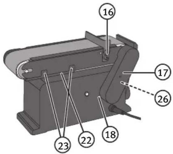
natural_image
Line drawing of hands operating a mechanical device with a tool (no text or symbols visible)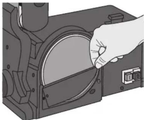
natural_image
Illustration of a hand inserting a circular component into a mechanical housing (no text or symbols visible)3.2 Montera/byt slipband
natural_image
Technical illustration of a mechanical device with labeled parts, showing top and side views (no text or symbols)natural_image
Line drawing of a sewing machine with a knob inserted, no text or symbols presentnatural_image
Technical line drawing of a mechanical device with mounting bracket and control panel (no text or symbols)natural_image
Technical line drawing of a mechanical device with rotating arm and base mount (no text or symbols)3.8 Strömbrytarens funktion
natural_image
Simple line drawing of a cabinet or latch mechanism with a circular button, no text or symbols present3.9 Placering
natural_image
Technical line drawing of a mechanical device with mounting brackets and mounting holes (no text or symbols)4. Användning
4.1 Vinkelslipning med slipbordet
natural_image
Technical line drawing of a mechanical device with mounting bracket and housing (no text or symbols)natural_image
Technical line drawing of a mechanical clamp or bracket assembly (no text or symbols)natural_image
Technical line drawing of a mechanical device with a magnified circular component (no text or symbols)5. Användningstips
natural_image
Symbol of a trash bin crossed with no text or numbers, representing waste sorting or restriction (no text present)8. Specifikationer
Spänning 230 V, 50 Hz
Effekt 500 W
Obelastad hastighet sliptallrik 2850 min
natural_image
Icon of a person reading a book inside a circle (no text or symbols)natural_image
Simple line drawing of a person wearing sunglasses and a mask, enclosed in a circle (no text or symbols)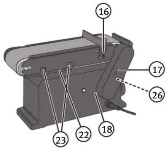
natural_image
Line drawing of hands operating a mechanical device with a tool (no text or symbols visible)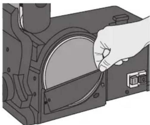
natural_image
Illustration of a hand inserting a circular component into a mechanical housing (no text or symbols visible)natural_image
Technical diagram of a mechanical assembly with labeled components (no text or symbols present)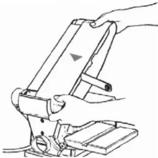
natural_image
Line drawing of a hand operating a mechanical device with a lever and base (no text or symbols)natural_image
Line drawing of a sewing machine with a needle inserted, no text or symbols presentnatural_image
Technical line drawing of a mechanical device with no visible text or symbols- Hvis bändet trekker ut fra slipetallerkenen, så skru justeringsrattet (8) ¼ omdreining moturs, sett fra driverullen.
- Start motoren og skru av med en gang, for å kontrollere de justeringene du nettopp gjorde. Juster en gang til hvis slipebåndet fremdeles ikke er sentrert.
natural_image
Technical line drawing of a mechanical device with rotating arm and base mount (no text or symbols)natural_image
Simple line drawing of a cabinet or latch with a circular button and handle, no text or symbols present.3.9 Plassering
natural_image
Technical line drawing of a mechanical device with mounting brackets and mounting holes (no text or symbols)4. Bruk
4.1 Vinkelsliping med slipebord
Slipebordet (19) kan stilles inn for sliping i vinklene 0–45°.
- Løsne låserattet (25) og hell bordet i ønsket vinkel.
- Trekk til låseskruen. Benytt den vedlagte gjæringslinjalen (20) ved sliping av små emner på slipetallerkenen.
a) Plasser emnet med den ene side mot denne linjalen.
b) Slip alltid mot den venstre siden på sliperondellen.
4.2 Planslipe på slipebåndet
natural_image
Technical line drawing of a mechanical device with mounting bracket and housing (no text or symbols)natural_image
Line drawing of a mechanical device with wooden frame and circular base (no text or symbols)natural_image
Technical line drawing of a mechanical device with a magnified circular component (no text or symbols)5. Brukertips
natural_image
Symbol of a trash bin crossed with no text or numbers, representing waste sorting or disposal (no text present)8. Spesifikasjoner
Spenning 230 V, 50 Hz
Effekt 500 W
Ubelastet hastighet slipeskiven 2850 min
Ubelastet hastighet slipebånd 7,35 m/sek
Slipeskive ∅ 150 mm
Bord 160 × 225 mm
Slipebånd 100 × 915 mm
Vinkler slipebord 0–45°
natural_image
Icon of a person using a laptop inside a circle (no text or symbols)natural_image
Simple line drawing of a person wearing glasses and a phone receiver, enclosed in a circle (no text or symbols)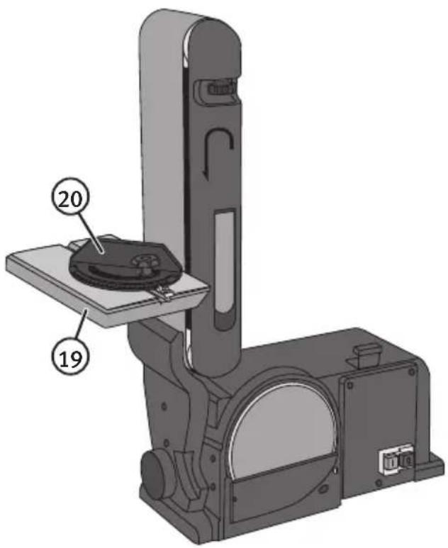
natural_image
Technical line drawing of hands operating a mechanical device with a tool (no text or symbols visible)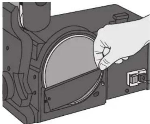
natural_image
Illustration of a hand holding a circular component with a switch, no text or symbols presentnatural_image
Technical illustration of a mechanical device with labeled parts, showing top and side views (no text or symbols)natural_image
Line drawing of a sewing machine with a needle inserted, no text or symbols presentnatural_image
Technical line drawing of a mechanical device with no visible text or symbolsnatural_image
Technical line drawing of a mechanical device with rotating arm and base mount (no text or symbols)natural_image
Simple line drawing of a cabinet or latch mechanism with a circular button and handle (no text or symbols)natural_image
Technical line drawing of a mechanical device with mounting brackets and a central circular component (no text or symbols)4. Käyttö
natural_image
Technical line drawing of a mechanical device with mounting bracket and housing (no text or symbols)natural_image
Technical line drawing of a mechanical device with wooden components and a circular base (no text or symbols)natural_image
Technical line drawing of a mechanical device with a magnified circular component (no text or symbols)5. Käyttövinkkejä
natural_image
Symbol of a trash bin crossed with no visible text or labels8. Tekniset tiedot
Jännite 230 V, 50 Hz
Teho 500 W
LwA = 92 dB(A), K = 3dB(A)
Paino
19 kg
Bandschleifmaschine
natural_image
Icon of a person reading a book inside a circle (no text or symbols)Achtung:
natural_image
Simple line drawing of a person wearing sunglasses and a mask, enclosed in a circle (no text or symbols)Achtung:
natural_image
Technical line drawing of hands operating a mechanical device with a tool (no text or symbols visible)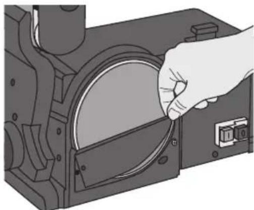
natural_image
Illustration of a hand inserting a circular component into a mechanical housing (no text or symbols visible)natural_image
Technical illustration of a mechanical device with a close-up view of its base assembly (no text or symbols present)natural_image
Line drawing of a sewing machine with a needle inserted, no text or symbols presentnatural_image
Technical line drawing of a mechanical device with no visible text or symbolsnatural_image
Technical line drawing of a mechanical device with rotating arm and side-mounted unit (no text or symbols)natural_image
Simple line drawing of a cabinet or latch mechanism with a circular button and handle (no text or symbols)natural_image
Technical line drawing of a mechanical device with mounting brackets and a central circular component (no text or symbols)4. Bedienung
natural_image
Technical line drawing of a mechanical device with mounting bracket and side panel (no text or symbols)natural_image
Line drawing of a mechanical device with wooden frame and circular base (no text or symbols)natural_image
Technical line drawing of a mechanical device with a magnified circular component (no text or symbols)natural_image
Symbol of a trash bin crossed with no text or labels, representing waste sorting or disposal (no text present)8. Technische Daten
Declaration of Conformity
Declares that this product complies with the requirements of the following directives and standards
Machinery Directive 2006/42/EC
EN 61029-1:2009
+A11:2010
EN 60745-2-4:2011
EMC Directive 2014/30/EU
EN 55014-1: 2006/
+A1:2009/+A2:2011
EN 55014-2: 1997/
+A1:2001/+A2:2008
EN 61000-3-2: 2014
EN 61000-3-3:2013
Henrik Alfredsson
Manager Technique & Quality
Insjön, Sweden, 2017-02-07
CLAS OHLSON AB, SE-793 85 INSJÖN, SWEDEN
Sverige
Postal 10 - 13 Market Place
Kingston Upon Thames
Surrey
KT1 1JZ
Deutschland
Kundenservice


- Viktig information:
- Belt and Disc Sander
- Contents
- Safety
- General safety instructions for your safety and the safety of others
- Specific safety regulations for bench sanders
- Key to warning symbols
- Product description
- Assembly and preparations
- Replacing the sanding disc
- Replacing the sanding belt
- Mounting the work table for use with the sanding disc
- Mounting the work table for use with the sanding belt
- Mounting the backstop
- Sanding belt tracking
- Using the sanding belt at different angles
- Power switch operation
- Placement
- Adjusting and changing the drive belt
- Operating instructions
- Bevel sanding using the work table
- Surface sanding on the sanding belt
- Sanding the ends of long workpieces
- Sanding curved surfaces
- Useful tips
- Troubleshooting
- Responsible disposal
- Specifications
- Bandslipmaskin
- Montera/byt slipband
- Strömbrytarens funktion
- Placering
- Användning
- Vinkelslipning med slipbordet
- Användningstips
- Specifikationer
- Plassering
- Bruk
- Vinkelsliping med slipebord
- Planslipe på slipebåndet
- Brukertips
- Spesifikasjoner
- Käyttö
- Käyttövinkkejä
- Tekniset tiedot
- Bandschleifmaschine
- Achtung:
- Bedienung
- Technische Daten
- Declaration of Conformity
- Sverige
- Deutschland
Brand : Cocraft
Model : HBD500
Category : Mill