HB-125 - Mill Cocraft - Free user manual and instructions
Find the device manual for free HB-125 Cocraft in PDF.


| Product Type | Electric Mill |
| Brand | Cocraft |
| Model | HB-125 |
| Power | 150 W |
| Voltage | 220-240 V, 50/60 Hz |
| Capacity | 100 g |
| Material | Stainless Steel Blades, Plastic Housing |
| Dimensions (L x W x H) | 12 cm x 12 cm x 22 cm |
| Weight | 1.0 kg |
| Cord Length | 80 cm |
| Functions | Grinding, Pulse Function |
| Safety Features | Lid Safety Lock, Overload Protection, Non-Slip Base |
| Cleaning | Wipe with damp cloth; Do not immerse in water |
| Spare Parts | Replacement Blades, Lid |
| Repairability | User-replaceable blades; professional repair for motor |
| Usage | Dry spices, coffee beans, nuts, herbs |
| Noise Level | Approx. 80 dB |
Frequently Asked Questions - HB-125 Cocraft
User questions about HB-125 Cocraft
0 question about this device. Answer the ones you know or ask your own.
Ask a new question about this device
Download the instructions for your Mill in PDF format for free! Find your manual HB-125 - Cocraft and take your electronic device back in hand. On this page are published all the documents necessary for the use of your device. HB-125 by Cocraft.
USER MANUAL HB-125 Cocraft
Read the entire instruction manual carefully and make sure that you fully understand it before you use the equipment. Keep the manual for future reference.
Viktig information:
Original instructions
Bruksanvisning i original
Originalbruksanvisning
Please read the entire instruction manual before using the product and then save it for future reference. We reserve the right for any errors in text or images and any necessary changes made to technical data. In the event of technical problems or other queries, please contact our Customer Services (see address details on the back).
Safety
General safety instructions
Warning! When using electric tools basic safety precautions should always be followed to reduce the risk of fire, electric shock and personal injury including the following. Read all these instructions before attempting to operate this product and save these instructions".
1. Keep work area clear
- Cluttered areas and benches invite injuries.
2. Consider work area environment
- Do not expose tools to rain.
- Do not use tools in damp or wet locations.
- Keep work area well lit.
- Do not use tools in the presence of flammable liquids or gases.
3. Guard against electric shock
- Avoid body contact with earthed or grounded surfaces (e.g. pipes, radiators, ranges, refrigerators).
4. Keep other persons away
- Do not let persons, especially children, not involved in the work touch the tool or the extension cord and keep them away from the work area.
5. Store idle tools
- When not in use, tools should be stored in a dry locked-up place, out of reach of children.
6. Do not force the tool
- It will do the job better and safer at the rate for which it was intended.
7. Use the right tool
- Do not force small tools to do the job of a heavy duty tool.
- Do not use tools for purposes not intended; for example do not use circular saws to cut tree limbs or logs.
8. Dress properly
- Do not wear loose clothing or jewellery, they can be caught in moving parts.
- Non-skid footwear is recommended when working outdoors.
- Wear protective hair covering to contain long hair.
9. Use protective equipment
- Use safety glasses.
- Use face or dust mask if working operations create dust.
10. Connect dust extraction equipment
- If the tool is provided for the connection of dust extraction and collecting equipment, ensure these are connected and properly used.
11. Do not abuse the cord
- Never yank the cord to disconnect it from the socket. Keep the cord away from heat, oil and sharp edges.
12. Secure work
- Where possible use clamps or a vice to hold the work. It is safer than using your hand.
13. Do not overreach
- Keep proper footing and balance at all times.
14. Maintain tools with care
- Keep cutting tools sharp and clean for better and safer performance.
- Follow instructions for lubricating and changing accessories.
- Inspect tool cords periodically and if damaged have them repaired by an authorized service facility.
- Inspect extension cords periodically and replace if damaged.
- Keep handles dry, clean and free from oil and grease.
15. Disconnect tools
- When not in use, before servicing and when changing accessories such as blades, bits and cutters, disconnect tools from the power supply.
16. Remove adjusting keys and wrenches
- Form the habit of checking to see that keys and adjusting wrenches are removed from the tool before turning it on.
17. Avoid unintentional starting
- Ensure switch is in "off" position when plugging in.
18. Use outdoor extension leads
- When the tool is used outdoors, use only extension cords intended for outdoor use and so marked.
19. Stay alert
- Watch what you are doing, use common sense and do not operate the tool when you are tired.
20. Check damaged parts
- Before further use of tool, it should be carefully checked to determine that it will operate properly and perform its intended function.
- Check for alignment of moving parts, binding of moving parts, breakage of parts, mounting and any other conditions that may affect its operation.
- A guard or other part that is damaged should be properly repaired or replaced by an authorized service centre unless otherwise indicated in this instruction manual.
- Have defective switches replaced by an authorized service centre.
- Do not use the tool if the switch does not turn it on and off.
21. Warning
- The use of any accessory or attachment other than one recommended in this instruction manual may present a risk of personal injury.
22. Have your tool repaired by a qualified person
- This electric tool complies with the relevant safety rules. Repairs should only be carried out by qualified persons using original spare parts, otherwise this may result in considerable danger to the user.
Specific safety rules for bench grinders
• Always use safety glasses and safety wear.
- Do not overtight the spindle nut.
- Set the distance between the grinding wheel and the tool rest to max 2 mm and between the grinding wheel and the spark guard to max 2 mm. Warning: If the distance exceeds 2 mm the grinding wheel is worn out and must be replaced immediately.
- Regularly remove the grinding dust which has accumulated around the bench grinder.
- Always keep arms, hands, fingers and body parts clear of the abrasive wheels when the bench grinder is in use.
- Do not use the bench grinder in explosive atmospheres or in the presence of flammable liquids or gases.
- Do not use the bench grinder before it has been assembled in accordance with the instructions in the Assembly section of this instruction manual.
- Use only grinding wheels or other accessories with a maximum operating speed at least as high as the rated no-load speed of the bench grinder.
- Carefully inspect the grinding wheel for cracks or flaws before use. Never use a damaged grinding wheel. Cracked or flawed grinding wheels must be replaced immediately.
- Never use a grinding wheel with a diameter greater or less than 125 mm. Read and follow the grinding wheel manufacturer's instructions for installation and use.
- Always have a grinding wheel or accessory mounted on both arbor shafts of the bench grinder when it is used.
- Grinding wheels can produce sparks and flying debris. Make sure that sparks are not directed towards the user, other bystanders or combustible materials.
- Never use the side walls of the grinding wheel, only use the face.
- Only use flange washers designed for use with the bench grinder.
- Switch the bench grinder off using the power switch and disconnect it from the power supply. Wait until the grinding wheel has completely stopped rotating before making any adjustments.
- Always check that the tool rest lock knob is tight before use.
- Always keep a firm grip on the workpiece you are grinding or buffing. If possible, hold the tool or workpiece in a designated jig or clamp.
- Avoid kickback by resting the workpiece on the tool rest and grinding on the lower half of the grinding wheel.
Product safety symbols

Please read the entire instruction manual before using and save it for future use.

Always use ear protection.

Always wear safety glasses or a visor and breathing protection.

Wear protective gloves.
Product description
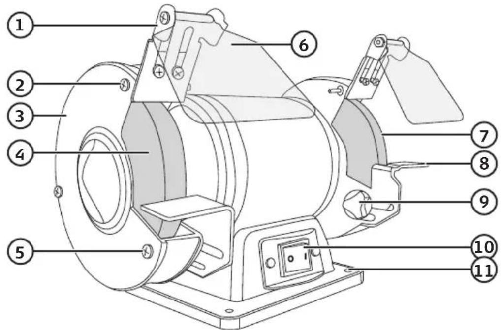
- Spark guard/eye shield bracket
- Shatter guard screw
- Grinding wheel shatter guard
- Grinding wheel (36 grit)
- Shatter guard and tool rest screw
-
Eye shield
-
Grinding wheel (60 grit)
-
Tool rest
-
Tool rest lock knob
-
[1]/[0] Power switch on/off
-
Mounting hole
Assembly
Warning: Plug the machine in only after completing all assembly and adjustment work and having read the user manual, all warnings and safety instructions.
- Mount the bench grinder onto a stable platform such as workbench using the four mounting holes (11). Use screws or bolts suitable for the supporting structure. Note: Steps 2–4 are to be carried out to both sides of the bench grinder.
-
Attach the tool rest (8) to the grinding wheel shatter guard (3) using the lock knob (9). The gap between the grinding wheel and the tool rest should be set to a maximum of 2 mm.
-
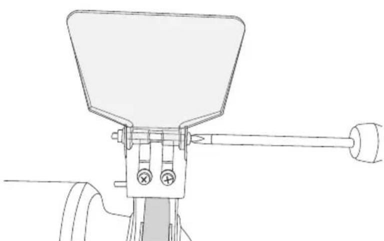
Attach the spark guard/eye shield bracket (1) to the shatter guard (3) using both the screws. The gap between the grinding wheel and the spark guard should be set to a maximum of 2 mm.
natural_image
Technical line drawing of a mechanical device with lever and base components (no text or symbols)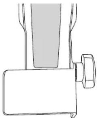
natural_image
Line drawing of a mechanical device with a handle and lever (no text or symbols)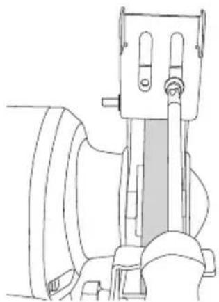
natural_image
Line drawing of a mechanical device with no visible text or symbols- Attach the eye shield (6) to the spark guard. Set the eye shield to the desired angle and tighten the screw so that the shield stays in place but can be swivelled up or down.
Operating instructions
Preparations
- Make sure that the grinding wheel can rotate freely before starting the machine.
- Adjust the eye shield so that you have a good view of the grinding operation.
- Check that the distance between the grinding wheel and the tool rest and between the grind wheel and spark guard is 2 mm or less.
Warning: The grinding wheel will wear down and become smaller after use which is why this check must always be made.
Grinding
- Plug the mains lead into a wall socket.
- Start the bench grinder using the power switch (10) and let it get up to speed before beginning to grind.
- Hold the workpiece in both hands and lay it on the tool rest. Move the workpiece slowly and steadily towards the grinding wheel. As pressure on the grinding wheel tends to lower the speed of the grinding wheel, you should occasionally reduce the pressure a little to let the wheel return to full speed.
- Keep the workpiece moving slowly from side to side across the whole face of the grinding wheel to prevent the wheel from wearing unevenly.
- If the workpiece becomes too hot to handle, dip it in some water or suitable cooling oil. Resume work when the workpiece has cooled.
- Turn the bench grinder off by setting the power switch to 0 and then unplug the grinder from the wall socket.
Warning:
- Small workpieces should be held with pliers or similar.
- Never grind on the sides of the grinding wheel, doing so may cause it to crack.
- As most materials get hot during grinding, you must be very careful with the workpiece.
Changing the grinding wheel
Warning: In order to prevent injury by accidentally starting the bench grinder, the machine must be turned off and the power plug disconnected from the socket before the grinding wheel is replaced.
Note:
- Do not remove the cardboard discs attached to the sides of the new grinding wheel because they aid the secure grip of the flange against the grinding wheel.
- Check the new grinding wheel for cracks or other visible damage before fitting. Never use a damaged grinding wheel.
-
Do not tighten the nut too much with a spanner because the grinding wheel may break.
-
Set the power switch to 0 and unplug the grinder from the wall socket before changing the grinding wheel.
- Raise the eye shield.
- Loosen the spark guard screws so the guard can be moved out of the way.
- Remove the screws holding the shatter guard and tool rest and remove the shatter guard.
- Hold the grinding wheel still and undo the spindle nut by turning it clockwise with a spanner.
- Remove the spindle nut, the outer flange washer and the old grinding wheel. The inner flange washer should be left on the spindle.
-
Fit the new grinding wheel and the outer flange washer onto the spindle. Tighten the spindle nut anticlockwise, not too tight.
-
Install the shatter guard and tool rest. Adjust the distance between the grinding wheel and tool rest to max 2 mm and tighten the screws.
- Set the distance between the grinding wheel and spark guard to max 2 mm and tighten the screws.
- Make sure that the grinding wheel can rotate freely before starting the machine.
- Stand to the side of the bench grinder. Start it and let it get up to speed to make sure the wheel is balanced before grinding.
Care and maintenance
Unplug the mains lead from the wall socket before cleaning. Clean the product using a soft, damp cloth. Use a mild detergent. Never use solvents or strong, abrasive cleaning agents.
Responsible disposal
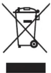
This symbol indicates that this product should not be disposed of with general household waste. This applies throughout the entire EU. In order to prevent any harm to the environment or health hazards caused by incorrect waste disposal, the product must be handed in for recycling so that the material can be disposed of in a responsible manner. When recycling your product, take it to your local collection facility or contact the place of purchase. They will ensure that the product is disposed of in an environmentally sound manner.
natural_image
Symbol of a trash bin crossed with no text or labels, accompanied by a blank rectangular block below (no text or symbols present)Specifications
Rated voltage 230–240 V AC, 50 Hz
Rated wattage S1 150 W, S2 (30 min) 250 W
No-load speed 2850 rpm
Grinding wheels ∅ 125 × 16 × ∅ 12.7 mm (1 × 60-grit, 1 × 36-grit)
Cable length 1.8 m
Weight 6 kg
Bänkslipmaskin
Art.nr 18-1378 Modell TDS-125A
41-2017
TDS-125A
natural_image
Technical line drawing of a mechanical device with lever and base (no text or symbols)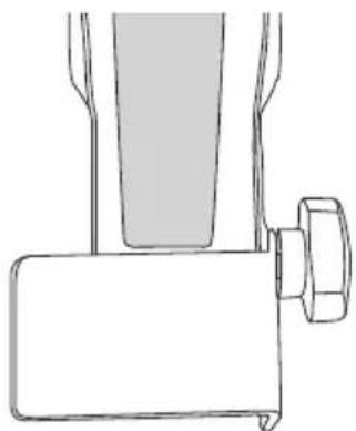
natural_image
Simple line drawing of a mechanical device with a handle and lever (no text or symbols)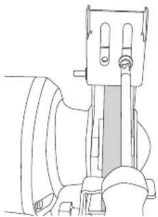
natural_image
Line drawing of a mechanical device with no visible text or symbolsnatural_image
Symbol of a trash bin crossed with no visible text or labelsSpecifikationer
Märkspänning 230–240 V AC, 50 Hz
Märkeffekt S1 150 W, S2 (30 min) 250 W
Varvtal, obelastad 2850 v/min
Slipskivor ∅ 125 × 16 × ∅ 12,7 mm (1 × medium-60, 1 × grov-36)
Kabellängd 1,8 m
Vikt 6 kg
Båndsliper
Art.nr. 18-1378 Modell TDS-125A-UK 41-2017 TDS-125A
- Gnistbeskyttelse/feste til beskyttelsesglass
- Festeskrue for beskyttelsesdeksel
- Beskyttelsesdeksel for slipeskive
- Slipskive (korn 36 - grov)
- Festeskrue for beskyttelsesdeksel og anlegg
-
Beskyttelsesglass
-
Slipskive (korn 60 - medium)
- Anlegg
- Låseratt for anlegg
- [1]/[0] Strømbryter på/av
- Monteringshull
Montering
natural_image
Technical line drawing of a mechanical device with lever and base (no text or symbols)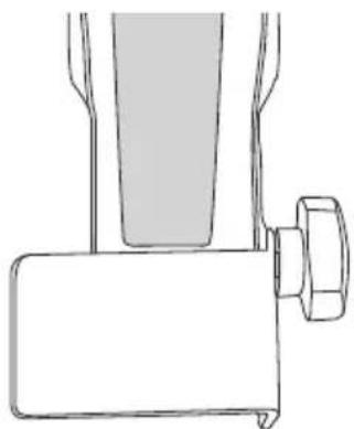
natural_image
Line drawing of a mechanical device with a cylindrical component and a rectangular base (no text or symbols)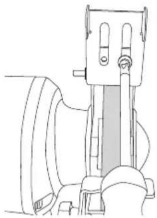
natural_image
Line drawing of a mechanical device with no visible text or symbolsnatural_image
Symbol of a trash bin crossed with no text or numbers, representing waste sorting or disposal (no text present)Spesifikasjoner
Spenning 230–240 V AC, 50 Hz
Effekt S1 150 W, S2 (30 min) 250 W
Turtall ubelastet 2850 o/min
Slipeskiver ∅ 125 × 16 × ∅ 12,7 mm (1 × medium-60, 1 × grov-36)
natural_image
Technical line drawing of a mechanical device with lever and base (no text or symbols)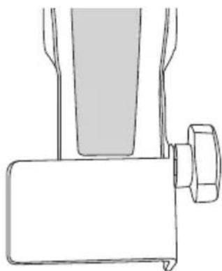
natural_image
Line drawing of a mechanical device with a cylindrical component and a rectangular base (no text or symbols)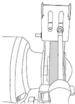
natural_image
Technical line drawing of a mechanical device with no visible text or symbolsnatural_image
Symbol of a trash bin crossed with no text or numbers, representing waste sorting or disposal (no text present)Tekniset tiedot
Jännite 230–240 V AC, 50 Hz
Nimellisteho S1 150 W, S2 (30 min) 250 W
natural_image
Line drawing of a mechanical device with a cylindrical component and a handle (no text or symbols)natural_image
Technical line drawing of a mechanical device with lever and base (no text or symbols)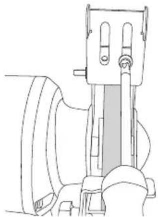
natural_image
Technical line drawing of a mechanical device with no visible text or symbolsnatural_image
Symbol of a trash bin crossed with no text or labels, accompanied by a black rectangular block below (no readable text or symbols)Technische Daten
Declaration of Conformity
Declares that this product complies with the requirements of the following directives and standards
Machinery Directive 2006/42/EC
EN:61029-1:2009+A11
EN:61029-2-4: 2011
EMC Directive 2014/30/EU
EN: 61000-3-2: 2014
EN: 61000-3-3: 2013
EN: 55014: 2006 +A1+A2
EN: 55014-2: 1997 +A1+A2
Low Voltage Directive
Henrik Alfredsson
Manager Technique & Quality
Insjön, Sweden, 2017-02-21
CLAS OHLSON AB, SE-793 85 INSJÖN, SWEDEN
Sverige
Postal 10 - 13 Market Place
Kingston Upon Thames
Surrey
KT1 1JZ
Deutschland
Kundenservice Hotline: 040 2999 78111
E-Mail: kundenservice@clasohlson.de
Homepage
www.clasohlson.de


- Viktig information:
- Safety
- General safety instructions
- Keep work area clear
- Consider work area environment
- Guard against electric shock
- Keep other persons away
- Store idle tools
- Do not force the tool
- Use the right tool
- Dress properly
- Use protective equipment
- Connect dust extraction equipment
- Do not abuse the cord
- Secure work
- Do not overreach
- Maintain tools with care
- Disconnect tools
- Remove adjusting keys and wrenches
- Avoid unintentional starting
- Use outdoor extension leads
- Stay alert
- Check damaged parts
- Warning
- Have your tool repaired by a qualified person
- Specific safety rules for bench grinders
- Product safety symbols
- Product description
- Assembly
- Operating instructions
- Preparations
- Grinding
- Warning:
- Changing the grinding wheel
- Note:
- Care and maintenance
- Responsible disposal
- Specifications
- Bänkslipmaskin
- Specifikationer
- Båndsliper
- Montering
- Spesifikasjoner
- Tekniset tiedot
- Technische Daten
- Declaration of Conformity
- Sverige
- Deutschland
Brand : Cocraft
Model : HB-125
Category : Mill