
PRO RG500-S - Laser pointer Cocraft - Free user manual and instructions
Find the device manual for free PRO RG500-S Cocraft in PDF.


| Product Type | Rotary Laser Level |
| Model | PRO RG500-S |
| Brand | Cocraft |
| Dimensions (Main Unit) | 160 × 160 × 185 mm |
| Weight (Main Unit) | 3 kg |
| Laser Class | Class 3R (IEC 60825-1) |
| Laser Wavelength (Green) | 510–520 nm |
| Maximum Output Power | <5 mW |
| Self-Levelling Range | ±5° |
| Accuracy | ±0.1 mm/m |
| Working Range (Without Receiver) | Up to 40 m |
| Working Range (With Receiver) | Up to 500 m |
| Rotation Speed | 0, 60, 120, 300, 600 rpm |
| Line Projection Angles | 10°, 45°, 90°, 180° |
| Power Supply | Rechargeable NiMH 4.0 Ah battery pack or 4 × C/LR14 batteries |
| Operating Time (Battery Pack) | Up to 16 hours |
| Operating Time (Alkaline Batteries) | Up to 40 hours |
| Charger Input | 100–240 V AC, 50/60 Hz |
| Charger Output | 5.6 V DC / 900 mA |
| Tripod Thread | 5/8" |
| IP Rating | IP54 (dust and splash water protected) |
| Operating Temperature | -10 to 50 °C (14 to 122 °F) |
| Included Accessories | Laser receiver, receiver holder, charger, remote control, battery holder, battery pack, green laser glasses, green target card, case |
| Manual Levelling Adjustment | Up to 5° in X and Y axis |
| Out of Level Warning | Yes, selectable |
Frequently Asked Questions - PRO RG500-S Cocraft
User questions about PRO RG500-S Cocraft
0 question about this device. Answer the ones you know or ask your own.
Ask a new question about this device
Download the instructions for your Laser pointer in PDF format for free! Find your manual PRO RG500-S - Cocraft and take your electronic device back in hand. On this page are published all the documents necessary for the use of your device. PRO RG500-S by Cocraft.
USER MANUAL PRO RG500-S Cocraft
Read the entire instruction manual carefully and make sure that you fully understand it before you use the equipment. Keep the manual for future reference.
Viktig information:
Original instructions
Bruksanvisning i original
Originalbruksanvisning
RG500-S Rotary Laser
Art.no 41-1265 Model FRE203 X-1-G
Please read the entire instruction manual before using the product and then save it for future reference. We reserve the right for any errors in text or images and any necessary changes made to technical data. In the event of technical problems or other queries, please contact our Customer Services (see address details on the back).
Safety
- This product generates laser radiation of laser class 3R in accordance with IEC 60825-1. Laser beams always pose a risk of blinding people and pets.
- On-product warning labels must be kept legible.
- Never point the laser beam towards people or animals and never look directly into the beam. Even low intensity lasers can cause permanent eye damage.
- If the product is mounted onto a tripod, make sure that it is fastened securely, that the tripod is fully open, locked and standing steadily on a firm surface.
- Do not use or store the product in temperatures other than those specified in the specifications below ( -10 to 50 ^ , 14 to 122 ^ ).
- Do not subject the product to extreme changes in temperature. Let it acclimatise to the ambient temperature before switching it on.
- This product contains no parts that you can repair yourself. This product must not be dismantled, opened or modified in any way.
- The product must only be repaired by qualified service technicians using original spare parts.
- The product is only intended for normal domestic use and only in the manner described in this instruction manual.
- The laser viewing glasses must not be used as safety glasses. The laser viewing glasses improve the visibility of the laser beam but do not protect eyes from laser radiation.
- Do not position the product in such a way that the laser beam can be reflected in mirrors or other reflective surfaces.
- Laser viewing glasses must not be used as normal sunglasses or in street traffic.
- Laser viewing glasses do not provide complete UV protection and reduce colour perception.
- Never point the laser beam at reflective material.
- This product is not a toy. Never let children play with the product. There is always a risk that someone will be inadvertently blinded.
- Never position the product in such a way that the laser beam projects at eye level and could possibly shine into someone's eyes.
- Never leave the product switched on unattended. Always switch it off after use. There is always a risk that someone could be blinded by the laser beam.
Laser classification
The rotatary laser emits a visible laser beam and is classed as a Class 3R laser in accordance with: IEC60825-1: 2014 Safety of laser products.
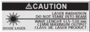
LASER RADIATION AVOID DIRECT EYE EXPOSURE.
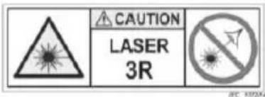
CLASS 3R LASER PRODUCT.
Caution – Use of controls or adjustments or performance of procedures other than those specified herein may result in hazardous radiation exposure (or alternatively, equivalent appropriate warnings).
- Do not stare into the laser beam or direct it towards other people or animals. Risk of serious damage to eyes.
- Never let the laser beam come close to eyes, even exposure to eyelids could cause eye damage.
- Caution: Do not look directly into the beam with optical aids such as binoculars or telescopes. Risk of serious damage to eyes.
- Make sure not to remove or damage the safety symbols and warnings found on the rotary laser.
- Never try to open the housing, repair or modify the rotary laser in any way.
- Only use accessories that are recommended by the manufacturer or retailer.
- Never use the rotary laser where explosive substances are used or stored.
- Do not use the rotary laser on or near highly reflective surfaces since the laser beam can be reflected back into your own or someone else's eyes.
- The instruction manual must always accompany the rotary laser. Anyone intending to use the laser must first read the entire instruction manual.
Package contents
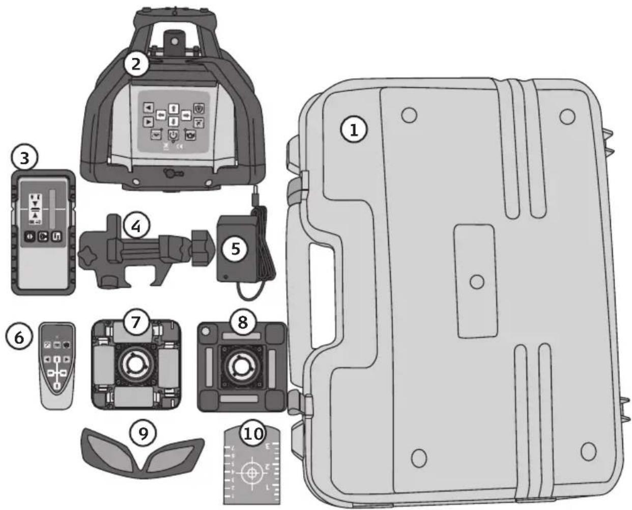
- Case
- Main unit
- Laser receiver
- Laser receiver holder for attaching the receiver to a levelling staff.
- Charger for included battery pack
- Remote control
- Battery holder (pictured batteries sold separately)
- Battery pack
- Green laser glasses
- Green target card
Main unit
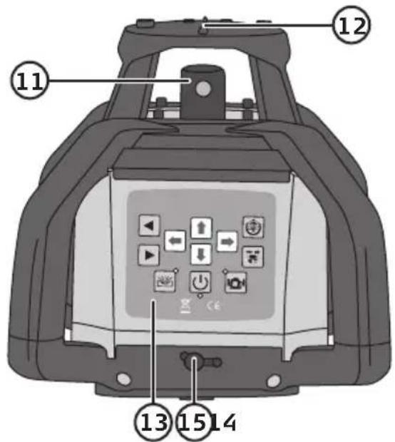
- Rotary laser for horizontal levelling
- Laser window for plumb dot
- Control panel
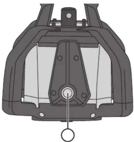
- Input socket for battery charger
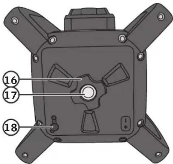
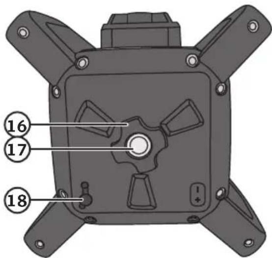
- Lock nut for battery pack/battery holder
- Tripod thread for horizontal levelling/laser window for plumb dot
- Input socket for battery charger
natural_image
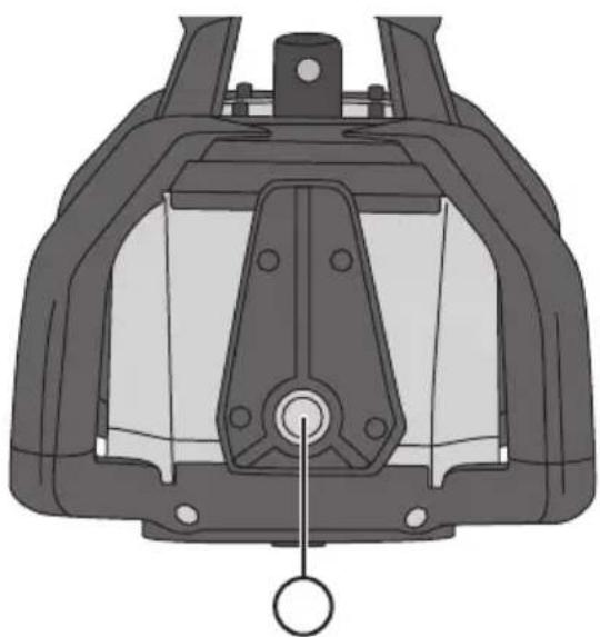
Technical diagram of a mechanical component with no visible text or symbols- Tripod tread for vertical levelling
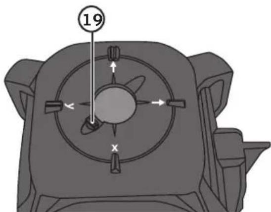
- Slider for closing the laser window for plumb dot
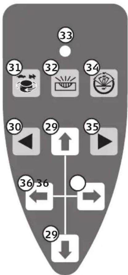
Control panel
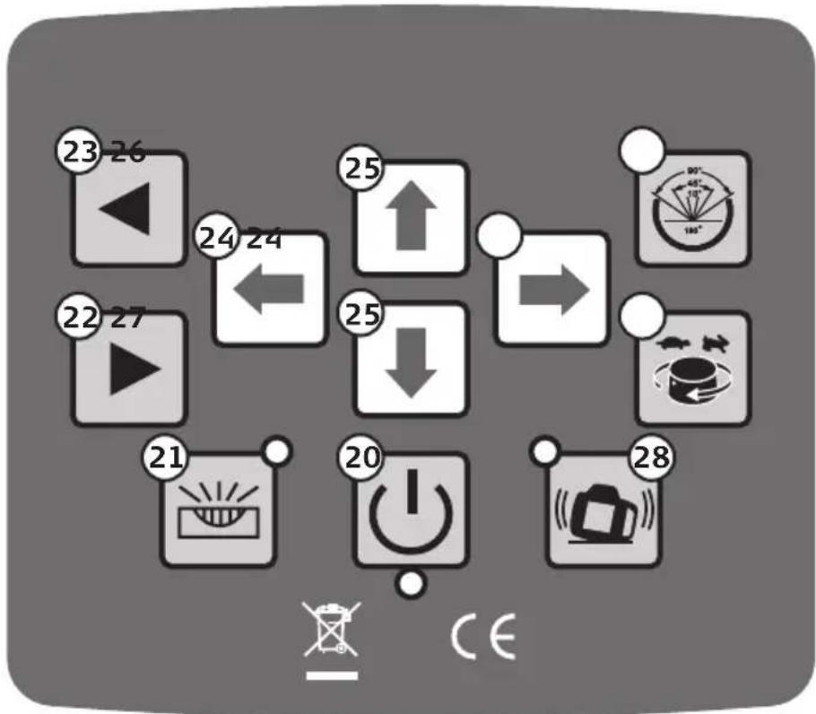
- [On/off
- [icon] Select automatic or manual levelling
- [▶] Moves the laser beam clockwise when you have limited the scanning angle to 10, 45, 90 or 180°
- [▶] Moves the laser beam anticlockwise when you have limited the scanning angle to 10, 45, 90 or 180°
- [←] [→] Manual levelling of the X-axis
- [↓] [↑] Manual levelling of the Y-axis
- [💡] Line, select fan angle 0–10, 0–45, 0–90 or, 0–180°
- [💡] Select rotation speed 0–60–120–300–600 rpm
- [💡] Out of level warning on/off
Most of the functions listed above can also be found on the remote controller.
Remote control
- [↓] [↑] Manual levelling of the Y-axis
- [◀] Laser beam rotates to the left
- [💡] Rotation speed 0–60–120–300–600 rpm
- [icon] Select automatic or manual levelling
- LED indicator
- [icon] Line, select fan angle 10, 45, 90 or, 180^
- [▶] Laser beam rotates to the right
- [←] [→] Manual levelling of the X-axis
flowchart
graph TD
    A["30"] --> B["29"]
    B --> C["35"]
    C --> D["36"]
    D --> E["29"]
    E --> F["36"]
    F --> G["29"]
    G --> H["36"]
    H --> I["29"]
    I --> J["36"]
    J --> K["29"]
    K --> L["36"]
    L --> M["29"]
    M --> N["36"]
    N --> O["29"]
    O --> P["36"]
    P --> Q["29"]
    Q --> R["36"]
    R --> S["29"]
    S --> T["36"]
    T --> U["29"]
    U --> V["36"]
    V --> W["29"]
    W --> X["36"]
    X --> Y["29"]
    Y --> Z["36"]
    Z --> AA["29"]
    AA --> AB["36"]
    AB --> AC["29"]
    AC --> AD["36"]
    AD --> AE["29"]
    AE --> AF["36"]
    AF --> AG["29"]
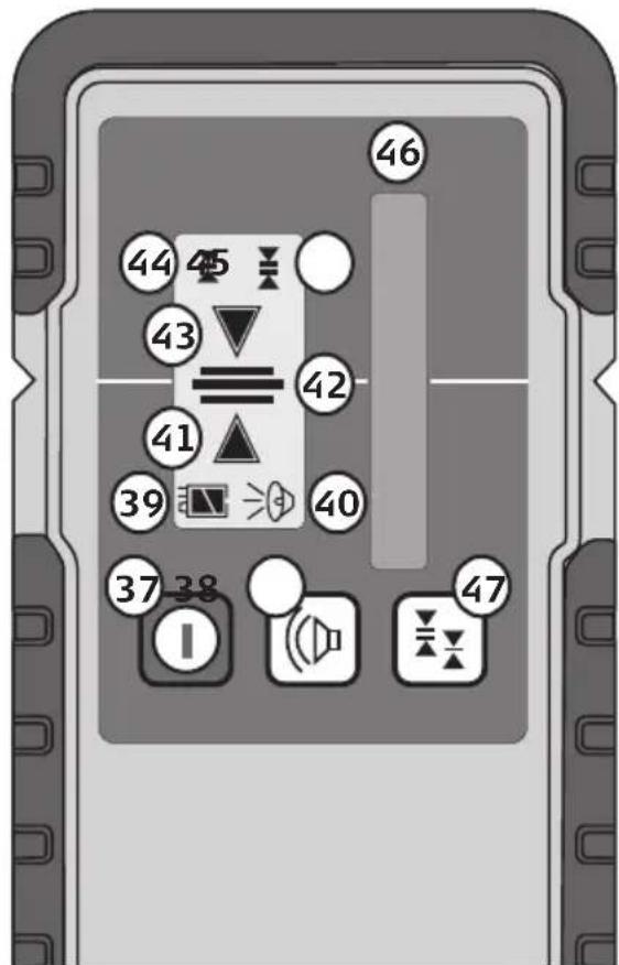
Laser receiver
- [①] Power button
- [☐] Audible signal on/off
- Battery charge status
- Audible signal on/off
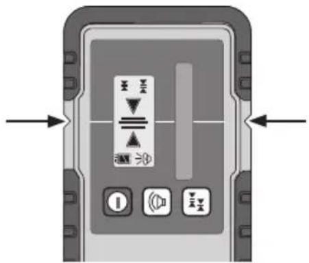
- The laser line is inside the sensor window but above the zero line. The receiver emits a short audible signal.
- The laser line is on the zero line. The receiver emits a continuous audible signal.
- The laser line is inside the sensor window but below the zero line. The receiver emits a slow audible signal.
- High sensitivity
- Low sensitivity
- Sensor window
- [☒] High/Low sensitivity. Long-press to illuminate the display. Long-press again to switch the display off.
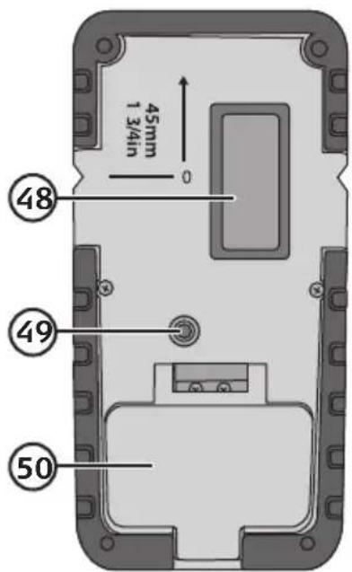
- Display
- Laser receiver mounting bracket
- Battery cover
Batteries
Main unit
You can use the included battery pack (8) or insert regular batteries into the included battery holder (7).
Battery pack
- Insert the battery pack into the laser level making sure that the contacts line up correctly (the battery pack only fits on in one way).
- Tighten the lock nut (16).
- Fully charge the battery before using the laser level for the first time. Charging time: approximately 7 hours.
- Connect the charger to a wall socket and to one of the power input sockets (14) or (18) on the laser level.
- The LED indicator shines red when the battery is being charged and changes to green when the battery is fully charged.
natural_image
Mechanical assembly diagram showing a piston and cylinder inside a housing (no text or symbols)Battery holder
-
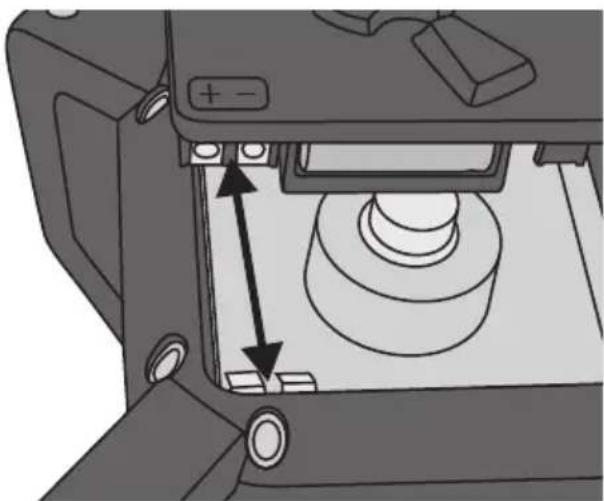
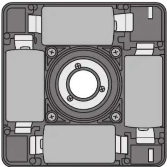
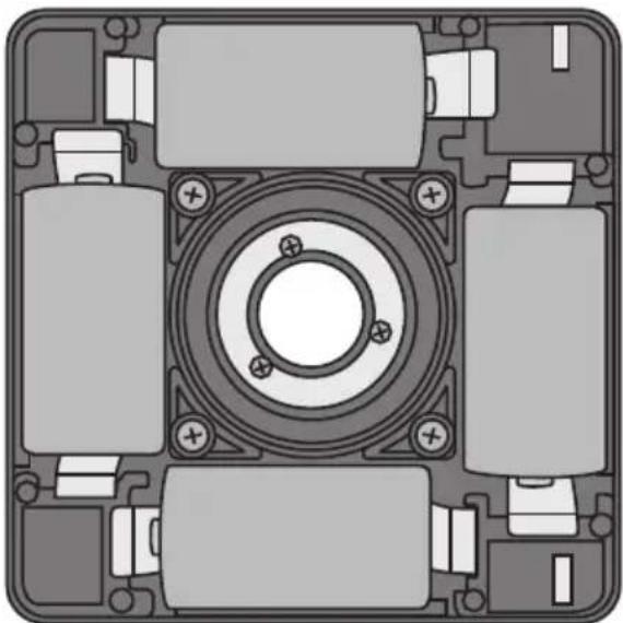
Insert 4 × C/LR14, 1.5 V batteries (sold separately). Refer to the markings in the battery holder to ensure correct polarity. Never mix old and new batteries. Never mix rechargeable and non-rechargeable batteries.
-
Insert the battery holder into the laser level making sure that the contacts line up correctly (the battery holder only fits on in one way).
-
Tighten the lock nut (16).
natural_image
Top-down schematic of a mechanical assembly with multiple cylindrical components and mounting holes (no text or symbols)Remote control
-
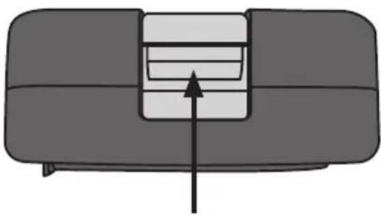
Open the battery compartment on the back of the remote control by sliding the cover in the direction of the arrow and insert 2 × AAA/LR03 batteries (sold separately). Refer to the markings in the battery compartment to ensure correct polarity.
-
Refit the battery cover.
Laser receiver
- Release the battery compartment cover catch and remove the cover.
- Insert 1 × 6LR61, 9 V battery (sold separately). Refer to the markings in the battery compartment to ensure correct polarity.
- Refit the battery cover.
natural_image
Simple line drawing of a sofa with a double door and an arrow pointing to the side panel (no text or symbols)Operating instructions
natural_image
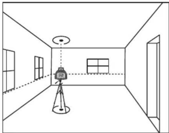
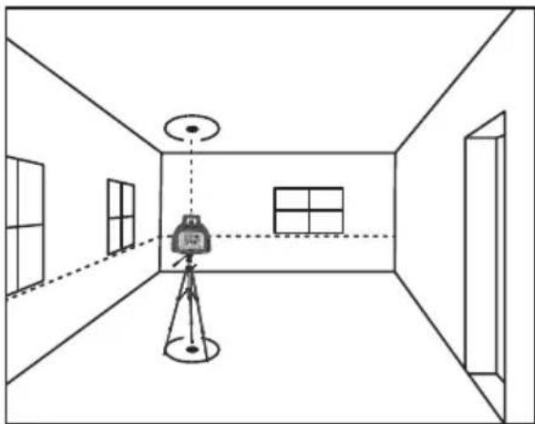
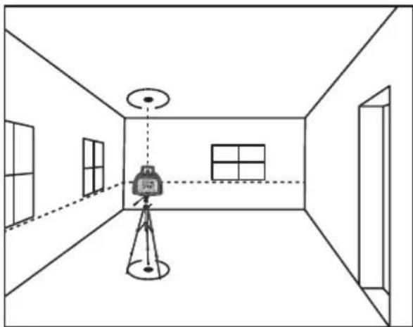
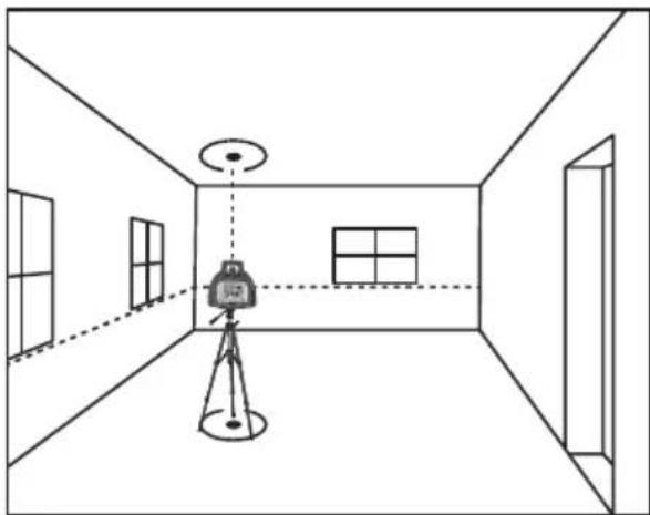
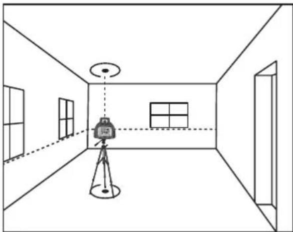
Simple line drawing of a room with a camera setup and ceiling light, no text or symbols presentThe laser can be placed/mounted horizontally or vertically and when in the horizontal position projects a horizontal laser line plus plumb dots upwards and downwards.
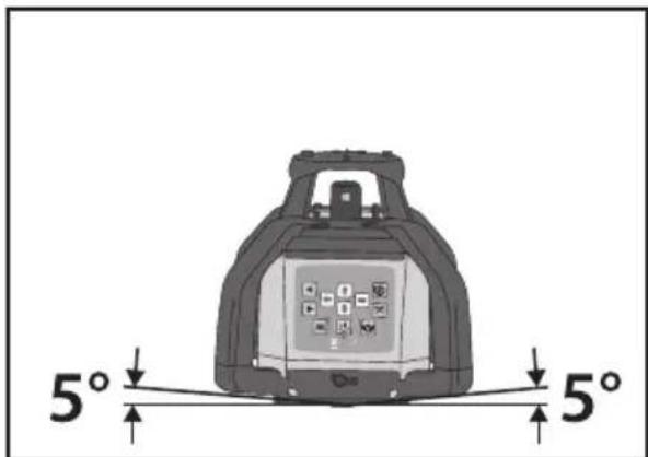
The laser level is self-levelling up to 5°.
natural_image
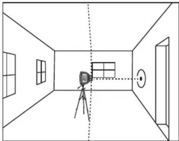
Interior view of a room with a camera setup and a projector, no text or symbols presentIn the vertical position it projects a vertical laser line plus horizontal laser dots.
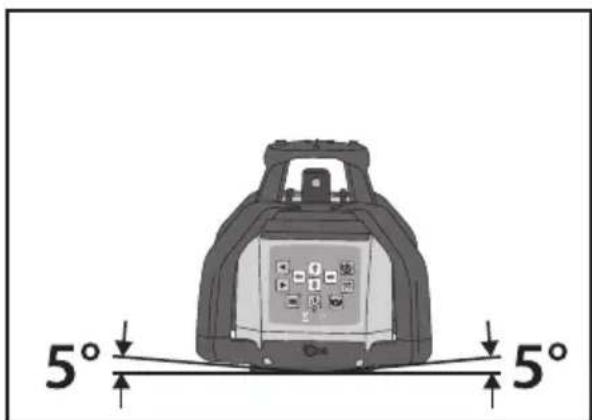
Note: If the temperature where the laser level is stored differs greatly from the temperature at which the level is to be used, the level should be allowed to acclimatise to the ambient temperature before it is used.
Self-levelling
- The self-levelling feature is automatically activated when the level is switched on. For the levelling function, one laser dot is aimed to the side and one upwards. When the laser level has levelled itself the laser will begin to rotate.
- If the laser level leans more than ± 5^ it will not start to rotate. If this happens, switch the laser level off, level it as best you can by hand and then switch it back on again.
Modes
Automatic or manual levelling
When it is switched on the laser level automatically enters automatic levelling mode.
Press [21] so that the green LED comes on to put the laser level into manual levelling mode. This allows you orientate the laser level at different angles, such as on slopes.
Line projection
Press [icon] (26) repeatedly to select the beam spread angle. Choose between 10, 45, 90 and 180^ .
Changing the rotation speed
Press [7] (27) repeatedly to limit the rotation speed of the laser. Choose between 0, 60, 120, 300 and 600 rpm.
Out of level warning
The Out of Level Warning feature is automatically deactivated when the level is switched on.
A deactivated out of level warning feature means that:
- The laser level is more tolerant of knocks than when the feature is activated.
- The laser level switches off if it is moved out of position or subjected to a heavy blow or jolt.
- The laser level automatically switches itself back on after having been knocked out of level by a heavy shock.
This feature can be used when you work relatively close to the instrument and are able to notice that it has been knocked out of line.
An activated out of level warning feature (press [1] (28) so that the LED on the button blinks to activate the feature) means that:
- The laser level is less tolerant of knocks than when the feature is deactivated.
- The laser level switches off if moved out of position or subjected to a blow or jolt.
- The laser level will not automatically switch itself back on after having been knocked out of level by a blow or jolt.
- The LED on the button will flash quickly to indicate this.
This feature is useful for when you are working relatively far away from the instrument and need to be alerted if it has been knocked out of position.
Note: The Manual Levelling and Out of Level features cannot both be used at the same time.
Moving the laser level in line projection mode
- Press [💡] to select a spread angle of 10, 45, 90 or 180^ .
- Press or hold down [▶] to move the laser line clockwise.
- Press or hold down [◀] to move the laser line anticlockwise.
Raise, lower or incline the laser line
With the laser level set up for horizontal levelling, press [icon] so that the green LED comes on and Manual Levelling mode is activated.
- Press [←] [→] to incline the laser line.
- Press [][] to raise/lower the laser line.
With the laser level set up for vertical levelling, press [icon] so that the green LED comes on and Manual Levelling mode is activated.
- Press [←] [→] to incline the laser line.
- Press [][] to move the laser line to the right or left.
3.
Using the laser level with the laser receiver
-
In poor lighting conditions or when used outdoors, the laser receiver can be used to help improve detection of the laser line. Mark the line using the mark on the receiver.
-
Long-press [✗] (47) to illuminate the display backlight. Long-press again to switch the display off.
Depth levelling
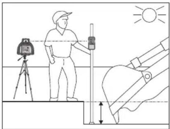
The picture below shows an example of how the receiver is used to create a uniform depth and level surface when digging trenches and foundations.
When the laser beam hits the sensor window, the receiver will emit repeated audible signals. When the laser beam is on the middle of the line in the sensor window the receiver will emit a continuous audible signal.
natural_image
Illustration of a person using surveying equipment to observe a vertical pole, with no text or symbols present.Inclined plane levelling
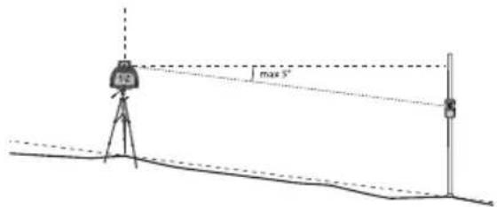
The picture below shows an example of levelling on an inclined plane. The laser line has been inclined (refer to the Modes section above) to create an even inclined plane. The laser line can be inclined up to 5°.
Laser viewing glasses
The laser enhancement glasses improve the visibility of the laser line in situations where it is difficult to see it, such as in bright light conditions or over long distances.
Note:
- Laser viewing glasses must not be used as safety glasses. They make it easier to see the laser beam but do not protect eyes from radiation.
- Laser viewing glasses must not be used as normal sunglasses or in street traffic. They do not protect against UV-radiation and impair colour perception.
Calibration check
If you wish to check the accuracy of the laser level, do so in the following way:
- Make sure that you have a free field of sight of about 20 m.
- Place the instrument onto a tripod or other stable surface.
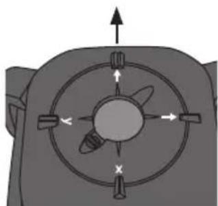
- Aim the "X" mark at the target point and switch the laser level on.
Note: Depending on the lighting conditions, you may need to use the line feature or receiver to mark the position of the laser line on the wall/target surface.
natural_image
Diagram of a mechanical component with directional arrows and cross symbols, no readable text or labels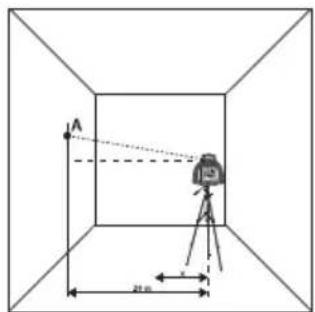
- Mark the position of the laser beam on the wall/target surface (A).
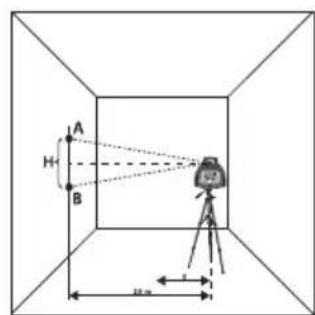
- Starting from the "X" mark, rotate the head of the laser level 180^ .
-
Mark the position of the laser beam (B).
-
Measure the distance (H) between point (A) and (B).
-
If the distance between the points is less than 4 mm the instrument is within its tolerance limits. If the distance is greater, the instrument should be sent to an authorised service centre for calibration.
Care, maintenance and storage
- Clean the laser level using a lightly moistened cloth. Use only mild cleaning agents, never solvents or corrosive chemicals.
-
If the laser level is not to be used for a long time:
-
Remove the batteries.
- Store the instrument where it is not exposed to vibrations and is out of reach of children.
- Ensure that the place of storage has a normal room temperature and is dry and dust free.
- Charge the battery pack at regular intervals to maintain the battery capacity.
Troubleshooting guide
| The laser will not switch on. | If you are using the battery packMake sure that the batteries are charged and correctly fitted.Refer to the Batteries section above.If you are using loose batteries in the battery holderCheck the capacity of the batteries and make sure that they are inserted correctly. Refer to the markings on the battery holder to ensure correct polarity. |
| The laser switches on but does not start, self-levelling fails. | The laser is inclined too much (over 5°). Right the laser level. |
| The laser line is not clear. | Check the batteries and replace if necessary.Check the laser window, clean it with a soft cloth if necessary.Ambient light level too high. |
Responsible disposal
This symbol indicates that this product should not be disposed of with general household waste. This applies throughout the entire EU. In order to prevent any harm to the environment or health hazards caused by incorrect waste disposal, the product must be handed in for recycling so that the material can be disposed of in a responsible manner. When recycling your product, take it to your local collection facility or contact the place of purchase. They will ensure that the product is disposed of in an environmentally sound manner.
natural_image
Symbol of a trash bin crossed with no text or numbers, representing waste sorting or disposal (no text present)Specifications
Main unit
Power Battery pack of rechargeable NiMH 4.0 Ah batteries or battery holder for 4 × C/LR14, 1.5 V batteries (sold separately)
Operating time Fully charged battery pack: up to 16 hours Alkaline batteries: up to 40 hours Continuous rotation: up to 16 hours regardless of battery type
Working range Without receiver: 40 m (depending on lighting conditions). With a receiver: up to 500 m regardless of lighting conditions.
Manual levelling adjustment Up to 5° in both the X and Y axis.
Self-levelling adjustment ±5^
Accuracy ±0.1 mm/m
Green laser Wavelength 510–520 nm, laser class 3R <5 mW, divergence < 0.2 mrad
Red laser Wavelength 650 nm, laser class 1
Variable rotation speed 60, 120, 300 and 600 rpm
Line projection angles 10, 45, 90 and 180°
Tripod thread 5/8"
Operating temperature -10 to 50 °C (14 to 122 °F)
IP rating IP54 (protected from dust and splashing water)
Size 160 × 160 × 185 mm
Weight 3 kg
Laser receiver
Batteries 1 × 6LR61, 9 V (sold separately)
Size 155 × 75 × 30 mm
Weight 260 g (with batteries)
Remote control
Batteries 2 × AAA/LR03 (sold separately)
Size 110 × 45 × 25 mm
Range Approx. 20 m
Operating temperature -20 to 50 °C (-4 to 122 °F)
Weight 65 g (with batteries)
Charger
In 100–240 V AC, 50/60 Hz
Out 5.6 V DC/ 900 mA
Rotationslaser RG500-S
Art.nr 41-1265 Modell FRE203 X-1-G
LASERPRODUKT KLASS 3R.
natural_image
Technical diagram of a mechanical component with no visible text or symbolsBatterier
Huvudenhet
natural_image
Mechanical assembly diagram showing a piston and housing component with directional arrows indicating movement (no text or symbols)Batterihållare
natural_image
Top-down schematic of a mechanical assembly with multiple components and mounting holes (no text or symbols)Fjärrkontroll
natural_image
Simple line drawing of a mechanical component with an arrow indicating direction (no text or symbols)Användning
natural_image
Interior view of a room with a camera setup and ceiling light, no text or symbols presentnatural_image
Interior view of a room with a camera setup and a circular light source, no text or symbols presentVid vertikal montering/placering projiceras en lodrät laserlinje samt vågräta laserpunkter.
Nivåmätning
natural_image
Illustration of a person using surveying equipment to observe a vertical pole, with no text or symbols present.Mätning av lutande plan
natural_image
Diagram of a mechanical component with directional arrows and cross symbols, no readable text or labels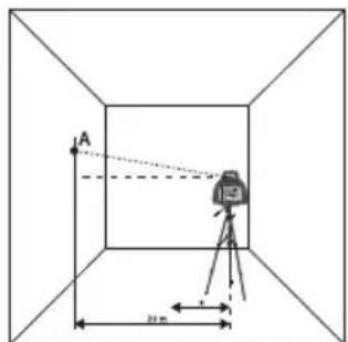
natural_image
Symbol of a trash bin with no text or labels, crossed by two diagonal lines and a horizontal bar below (no readable text or symbols)Specifikationer
Huvudenhet
In 100–240 V AC, 50/60 Hz
Ut 5,6 V DC/900 mA
LASERPRODUKT KLASSE 3R.
- Roterende laser til horizontal nivellering
- Laservindu for å lodde opp
- Kontrollpanel
- Uttak for batterilader
- Låsemutter for batteripack/batteriholder
- Stativfeste ved horisontal nivellering/laservindu for loddepunkt
- Uttak for batterilader
natural_image
Technical diagram of a mechanical component with no visible text or symbolsBatterier
Hovedenhet
natural_image
Mechanical assembly diagram showing a piston and housing component with directional arrows indicating movement (no text or symbols)Batteriholder
- Sett i batterier, 4 × C/LR14, 1,5 V (selges separat) i batteriholderen. Følg merkingen for polaritet i bunnen av batteriholderen. Bland aldri nye og gamle batterier. Bland heller ikke ladbare og ikke ladbare batterier.
- Monter batteriholderen i laseren og pass på at tilkoblingskontakten kommer på riktig plass (batteriholderen kan kun settes i på én måte).
- Trekk til läsemutteren (16).
natural_image
Top-down schematic of a mechanical assembly with multiple components and mounting holes (no text or symbols)Fjernkontroll
natural_image
Simple line drawing of a mechanical component with an arrow indicating direction (no text or symbols)Bruk
natural_image
Simple line drawing of a room with a camera mounted on a tripod, showing perspective projection lines (no text or symbols)natural_image
Interior view of a room with a camera setup and window, no text or symbols presentVed vertikal montering/plassering projiseres en loddrett laserlinje og vannrette laserpunkter.
Nivåmåling
natural_image
Illustration of a person using surveying equipment to observe a vertical pole, with no text or symbols present.natural_image
Diagram of a mechanical or electrical component with directional arrows and cross symbols, no readable text or labels.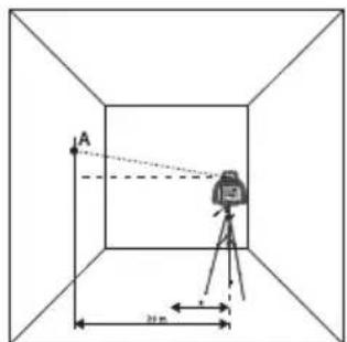
- Gå ut fra «X»-merkingen og drei laseren 180°.
-
Marker laserstrålens posisjon (B).
-
Mål avstanden (H) mellom punkt (A) og (B).
- Hvis avstanden mellom punktene er mindre enn 4 mm er laseren innenfor toleranse-området. Hvis avstanden er større bør laseren leveres til et autorisert serviceverksted.
natural_image
Symbol of a trash bin crossed with two crossed lines, no text or labels presentSpesifikasjoner
Hovedenhet
Drift Batteripack med ladbare NiMH-batterier 4,0 Ah eller batteriholder for 4 × C/LR14, 1,5 V-batterier (selges separat)
natural_image
Technical diagram of a mechanical component with no visible text or symbolsVirtalähde
Pääyksikkö
natural_image
Mechanical assembly diagram showing a piston and housing component with directional arrows indicating movement (no text or symbols)Paristolokero
natural_image
Top-down schematic of a mechanical assembly with multiple components and mounting holes (no text or symbols)Kaukosäädin
natural_image
Simple line drawing of a mechanical component with an arrow indicating direction (no text or symbols)Käyttö
natural_image
Simple line drawing of a room with a camera mounted on a tripod, showing perspective projection lines (no text or symbols)natural_image
Interior view of a room with a camera setup and window, no text or symbols presentTason mittaus
natural_image
Illustration of a person using surveying equipment to observe a vertical pole, with no text or symbols present.natural_image
Diagram of a mechanical component with directional arrows and cross symbols, no readable text or labels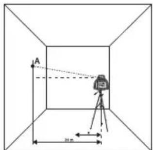
natural_image
Symbol of a trash bin crossed with no text or labels, representing waste sorting or disposal (no text present)Tekniset tiedot
Pääyksikkö
LASERPRODUKT KLASSE 3R.
natural_image
Technical diagram of a mechanical component with no visible text or symbolsBatterien
Basiseinheit
natural_image
Mechanical assembly diagram showing a piston and cylinder inside a housing (no text or symbols)Batteriehalterung
natural_image
Top-down schematic of a mechanical assembly with multiple components and mounting holes (no text or symbols)Fernbedienung
natural_image
Diagram of a mechanical component with an arrow indicating direction (no text or symbols)Benutzung
natural_image
Simple line drawing of a room with a camera mounted on a tripod, showing perspective projection lines (no text or symbols)natural_image
Interior view of a room with a camera setup and window, no text or symbols presentNiveaumessung
natural_image
Illustration of a person using surveying equipment to measure height, with no visible text or symbols.natural_image
Diagram of a mechanical component with directional arrows and central hub (no text or symbols)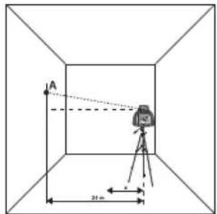
natural_image
Simple line drawing of a trash bin with crossed lines indicating no waste or restriction (no text or symbols)Technische Daten
Basiseinheit
Stromversorgung
Declaration of Conformity
Declares that this product complies with the requirements of the following directives and standards
Machinery Directive EM
C Directive
2014/30/EU
Low Voltage Directive
2014/35/EU
EN: 61000-6-3: 2007
+A1:2011
EN: 61000-6-1: 2007
EN 61010-1:2010
EN 60825-1: 2014
Henrik Alfredsson
Manager Technique & Quality
Insjön, Sweden, 2017-05-12
CLAS OHLSON AB, SE-793 85 INSJÖN, SWEDEN
Sverige
Postal 10 - 13 Market Place
Kingston Upon Thames
Surrey
KT1 1JZ
Deutschland
Kundenservice Hotline: 040 2999 78111
E-Mail: kundenservice@clasohlson.de
Homepage
www.clasohlson.de


- Viktig information:
- RG500-S Rotary Laser
- Safety
- Laser classification
- Main unit
- Control panel
- Remote control
- Laser receiver
- Batteries
- Battery pack
- Battery holder
- Operating instructions
- Self-levelling
- Modes
- Automatic or manual levelling
- Line projection
- Changing the rotation speed
- Out of level warning
- Moving the laser level in line projection mode
- Raise, lower or incline the laser line
- Using the laser level with the laser receiver
- Depth levelling
- Inclined plane levelling
- Laser viewing glasses
- Note:
- Calibration check
- Care, maintenance and storage
- Troubleshooting guide
- Responsible disposal
- Specifications
- Charger
- Rotationslaser RG500-S
- Batterier
- Huvudenhet
- Batterihållare
- Fjärrkontroll
- Användning
- Nivåmätning
- Mätning av lutande plan
- Specifikationer
- Hovedenhet
- Batteriholder
- Fjernkontroll
- Bruk
- Nivåmåling
- Spesifikasjoner
- Virtalähde
- Pääyksikkö
- Paristolokero
- Kaukosäädin
- Käyttö
- Tason mittaus
- Tekniset tiedot
- Batterien
- Basiseinheit
- Batteriehalterung
- Fernbedienung
- Benutzung
- Niveaumessung
- Technische Daten
- Stromversorgung
- Declaration of Conformity
- Sverige
- Deutschland
Brand : Cocraft
Model : PRO RG500-S
Category : Laser pointer