
Mini Converter - Receiver Blackmagic Design - Free user manual and instructions
Find the device manual for free Mini Converter Blackmagic Design in PDF.


| Product Type | SDI to HDMI / HDMI to SDI Converter |
| Brand | Blackmagic Design |
| Model | Mini Converter (range) |
| Category | Receiver / Converter |
| Power Supply | 12 V DC via mains adapter (supplied) |
| Power Consumption | Approx. 5 W |
| Input Connectors | SDI BNC, HDMI type A (depending on model) |
| Output Connectors | SDI BNC, HDMI type A, 1/4" audio jack |
| Supported Video Formats | SD, HD, 3G-SDI, 6G-SDI, Ultra HD (depending on model) |
| Supported Audio | 16 embedded SDI channels, balanced analog, AES/EBU |
| Dimensions (approx.) | 140 x 73 x 18 mm |
| Weight (approx.) | 200 g |
| Operating Temperature | 0 °C to 40 °C |
| Housing Material | Robust aluminum |
| Key Features | SDI↔HDMI conversion, down-conversion, audio extraction, SDI ALT redundancy, 3D LUT support (depending on model) |
| Settings | DIP switches or Blackmagic Converters Setup software (via USB) |
| Firmware Update | Via USB port and Blackmagic Converters Setup software |
| Maintenance and Cleaning | Clean with a soft, dry cloth. Disconnect before cleaning. |
| Safety | Do not open the housing. Use the supplied adapter. Avoid moisture. |
| Spare Parts and Repairability | Not user repairable. No spare parts available. Contact technical support. |
| General Information | 36-month warranty (excluding connectors and cables). Manufactured by Blackmagic Design. |
Frequently Asked Questions - Mini Converter Blackmagic Design
User questions about Mini Converter Blackmagic Design
0 question about this device. Answer the ones you know or ask your own.
Ask a new question about this device
Download the instructions for your Receiver in PDF format for free! Find your manual Mini Converter - Blackmagic Design and take your electronic device back in hand. On this page are published all the documents necessary for the use of your device. Mini Converter by Blackmagic Design.
USER MANUAL Mini Converter Blackmagic Design
Installation and Operation Manual
Blackmagic Converters
June 2018
English, 日本語, Français, Deutsch, Español, 中文, 한국어, Русский, Italiano, Português and Türkçe.
Languages
To go directly to your preferred language, simply click on the hyperlinks listed in the contents below.
English 3
日本語 92
Français 182
Deutsch 272
Español 362
中文 452
한국어 542
Русский 632
Italiano 722
Português 812
Türkçe 902

natural_image
Circular portrait photo of a smiling man with short hair and glasses (no text or symbols visible)Welcome
Thank you for purchasing Blackmagic Converters for your production needs.
Blackmagic Mini Converters, Mini Converter Heavy Duty, Battery Converters and Micro Converters give you a solution for virtually any conversion you could need. Mini Converters convert analog to digital, digital to analog, SDI to audio, audio to SDI, up, down and cross conversion, SDI distribution, and can even provide a sync generator for locking all your video equipment to the same reference signal. Mini Converter Heavy Duty gives you the same conversions in a super tough design that's perfect for use on location and Battery Converters let you work on location with or without external power. Blackmagic Micro Converters are even smaller, designed for popular conversions such as SDI to HDMI and HDMI to SDI so you can plug any HDMI output into SDI video recorders and switchers, or plug SDI video equipment into HDMI monitors.
This instruction manual contains all the information you need to start using your Blackmagic Converters.
Please check the support page on our web site at www.blackmagicdesign.com for the latest version of this manual and for updates if your Blackmagic Converter has internal software. Keeping your internal software up to date will always ensure you get all the latest features. When downloading software, please register with your information so we can keep you updated when new software is released. We are constantly working on new features and improvements, so we would love to hear from you!
Grant Petty
Grant Petty
CEO Blackmagic Design
Contents
Blackmagic Converters
Getting Started 5 Mini Converter HDMI to SDI 4K 34
Plugging in Power 5 Mini Converter HDMI to SDI 6G 37
Plugging in Video 6 Mini Converter SDI to Analog 40
Plugging in Audio 7 Mini Converter SDI to Analog 4K 45
Installing Administration Software 8 Mini Converter Analog to SDI 49
Installing Blackmagic Converters Setup 8 Mini Converter SDI to Audio 53
Updating the Internal Software 9 Mini Converter SDI to Audio 4K 56
Updating Mini Converter SDI Mini Converter Audio to SDI 59
Distribution 4K 10 Mini Converter Audio to SDL4K 63
Changing Settings 11 Mini Converter Optical Fiber 67
Changing Settings using Switches 11 Mini Converter Optical Fiber 4K 68
Changing Settings using Mini Converter Optical Fiber 12G 69
Blackmagic Converters Setup 12
About Tab 13 Mini Converter Quad SDF to HDMI 4K 70
Blackmagic Converter Models 13
Teranex Mini Converters 13
Blackmagic Micro Converters 14
Micro Converter SDI to HDMI 14
Micro Converter HDMI to SDI 15
Micro Converter BiDirectional SDI/HDMI 17 Converter Setup Utility 86
Blackmagic Mini Converters 19 Blackmagic Battery Converters 87
Mini Converter SDI to HDMI 19 Battery Converter SDI to HDMI 87
Mini Converter SDI to HDMI 4K 22 Battery Converter HDMI to SDI 88
Mini Converter SDI to HDMI 6G 26 Help 90
Mini Converter HDMI to SDI 31 Warranty 91
Getting Started
Getting started with your Blackmagic Converter is as simple as plugging in power, plugging your source video into your converter's video input, and plugging the video output into your destination equipment.
Plugging in Power
Plug in the included 12 volt power supply using the socket adapter for your country. If your converter has a built in cable tie point, you can easily secure the power connection to your converter.
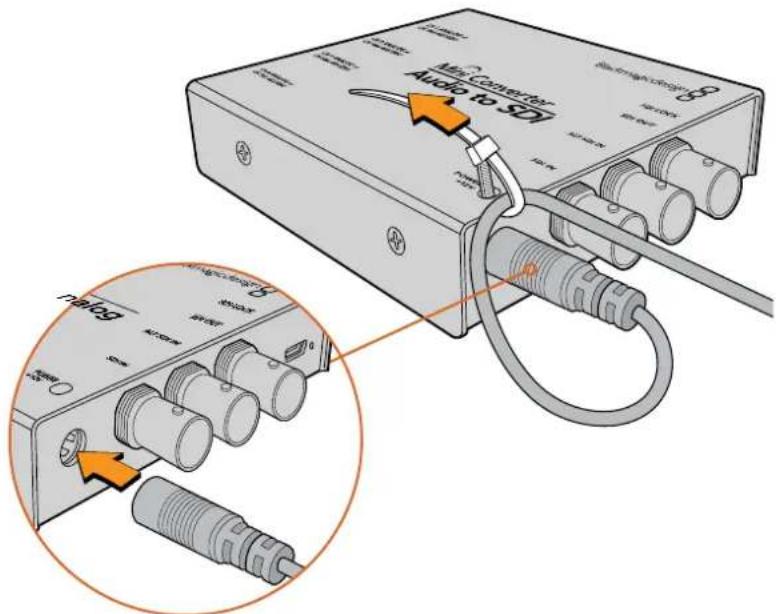
Locking the power cable to the converter's cable tie point prevents accidental disconnection.
Micro Converter
Blackmagic Micro Converter is powered using the micro USB connector. This gives you a convenient and flexible power solution. For example you can easily connect power using the battery charger for some modern cell phones, or even power your converter via the USB port of your laptop computer. Any device capable of providing 5V via a standard USB to Micro USB cable can power your Blackmagic Micro Converter.
Battery Converters
Blackmagic Battery Converters have a switch labeled 'On Batt Off' that is used to switch between mains power and battery power. When set to 'On', the Battery Converter will keep working even if external power is lost. When set to 'Off', only external power is used to ensure built in battery power is saved. The LED near the switch indicates the battery charge level by a continuous illumination for 100 percent charge, three flashes for 50 to 90 percent charge, two flashes for 10 to 50 percent charge and a single flash if less than 10 percent charge is remaining.
Plugging in Video
To connect your video inputs and outputs, simply plug your source video into your converter's video input and plug the video output into your destination equipment.
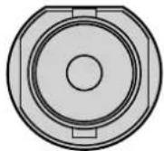
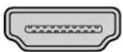
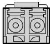
BNC HDMI Optical Fiber
Depending on your Blackmagic Converter model, the video connectors may be BNC, HDMI, or optical fiber LC.
Optical Fiber Connectors
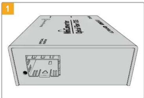
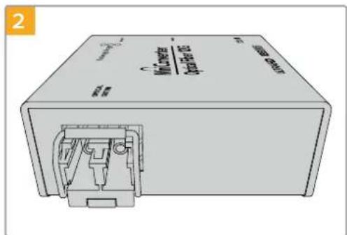
Some Blackmagic Converter models include an SFP socket to accept a compatible SFP optical fiber module that supports up to 3G, 6G or 12G-SDI video. The module is an optical transmitter and receiver with sockets for optical fiber cables.
natural_image
Illustration of a beige wireless device with ports labeled 'Wuweiser' and 'Copper 205', showing internal components (no readable text beyond labels)Examine the Optical Out/In socket to make sure it is free of dust.
natural_image
Illustration of a rectangular electronic device with internal components and a labeled port (no readable text or symbols)Remove the protective cover from the SFP optical fiber module, and insert it in the SFP socket. A locking pin clicks into position to secure the module in the socket.
natural_image
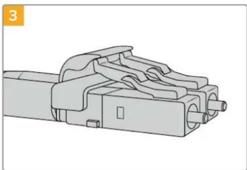
Technical line drawing of a mechanical component with multiple ports and housing (no text or symbols)The optical fiber cables have latching tabs on top to make sure they don't fall out.
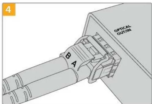
Plug in the optical fiber cables. Confirm the Out and In plugs are in the correct sockets, and that the locking tabs on the plugs hold the lever of the SFP optical fiber module upright.
Fail Safe Alternate SDI inputs
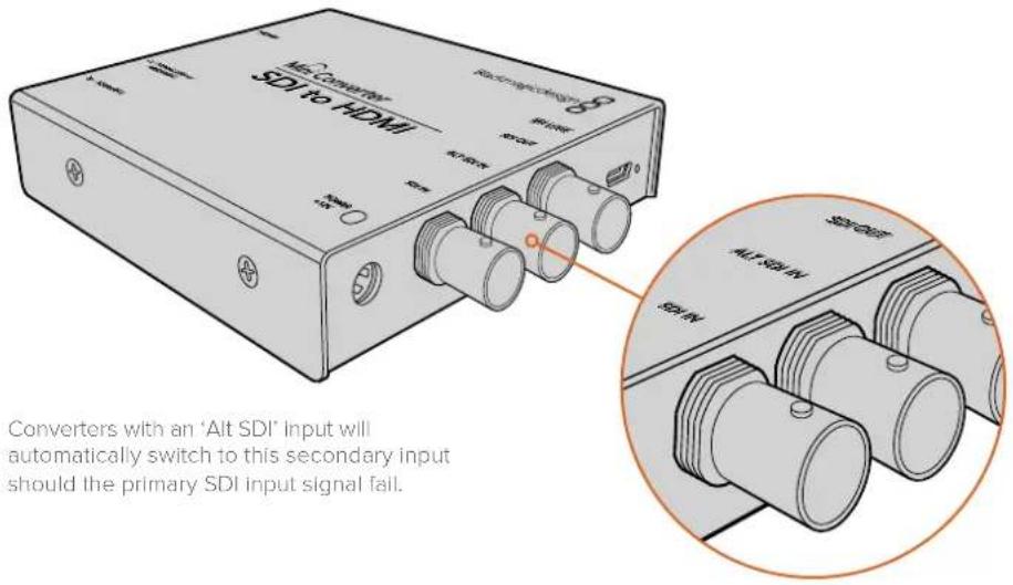
Some Blackmagic Converter models include alternative SDI inputs for redundancy. These inputs are labeled 'Alt SDI In' and will immediately take over should the primary SDI input signal fail. In this rare scenario, the SDI LOCK LED will flash, indicating that the converter has switched to the ALT SDI input.
Plugging in Audio
Jack Audio Connectors
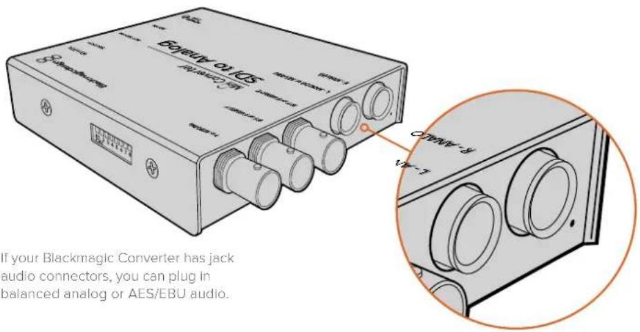
Some Blackmagic Converters have built in 1/4" jacks, so you can easily plug in balanced external analog or digital AES/EBU audio. The 1/4" jacks are balanced TRS connectors. TRS stands for Tip, Ring, Sleeve which refers to the three contacts of the jack connector.
Below is an illustration showing the wiring pins inside the male 1/4" jack connector if you want to make your own audio cables.
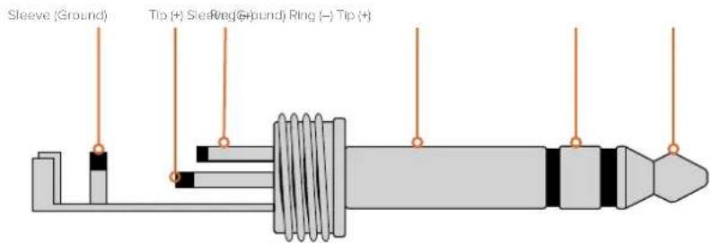
The audio jack illustration on the previous page shows the jack connector's positive, negative and ground wiring pins. If you need to reverse the polarity of your analog audio cable to suit your audio equipment, you can simply swap the positive and negative wiring on the tip and ring pins.
NOTE If you are connecting stereo analog audio, it's worth mentioning that if you reverse the polarity for one channel jack connector, make sure you do the same for the second or your stereo analog audio will be out of phase.
Installing Administration Software
Installing Blackmagic Converters Setup
Blackmagic Converters Setup is used to change settings on your converter and to update your converter's internal software. The settings available will depend on the converter you are using. However, some Blackmagic Converters don't require any adjustable settings and don't have internal software, therefore these particular converters will not have a USB connector. If your converter is one of these, you can go straight to your converter model in this manual to learn more about it.
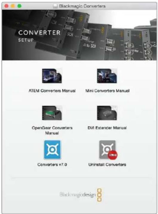
Blackmagic Converters Setup can be installed on Mac OS X and Windows computers.
Installation on Mac OS X
1 Download the Blackmagic Converters Setup software from www.blackmagicdesign.com
2 Unzip the downloaded file and open the resulting disk image to reveal its contents.
3 Double click the installer and follow the prompts to complete the installation.
4 When the installation has finished, click 'close'. Blackmagic Converters Setup is now installed.
Installation on Windows
1 Download Blackmagic Converters Setup from www.blackmagicdesign.com
2 Unzip the downloaded file. You should see a Blackmagic Converters Setup folder containing this PDF manual and the Blackmagic Converters Setup installer.
3 Double click the installer and follow the prompts to complete the installation.
4 Click 'finish' to complete the installation.
Blackmagic Converters Setup is now ready to use.
Updating the Internal Software
If your Blackmagic Converter has a USB connector, then you may have additional settings you can change, plus you can update your converter with the latest internal software. The latest software can be downloaded from the Blackmagic Design support center at www.blackmagicdesign.com/support.
When updating Blackmagic Micro Converters, power is already supplied via the USB port, so you don't have to worry about connecting power.
On Blackmagic Mini Converters, Battery Converters and Mini Converters Heavy Duty, you'll need to ensure your converter is powered before connecting to your computer via USB.
1 Power your converter.
2 Attach a USB cable from the computer to the converter and launch the Blackmagic Converter Setup.
Your Blackmagic Converter will be displayed on the setup utility's home page. If you have more than one converter connected via USB, click on the arrow icons on the left or right side of the home page to select your desired converter.
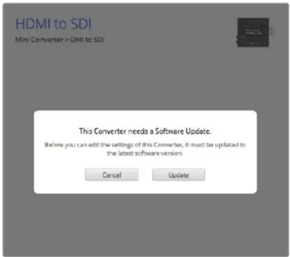
If Blackmagic Converters Setup detects an earlier version of your converter's internal software, it will prompt you to update.
If no converter is connected, the home page will display "no converters found". If you have a converter connected to your computer via USB, but you don't have power plugged in, the home page may display 'no power connected'. Simply plug power into your converter to access the settings.
If Blackmagic Converters Setup contains newer internal software than that currently installed in your Blackmagic Converter, it will prompt you to update. Simply follow the on screen instructions to complete the update.
Updating Mini Converter SDI Distribution 4K
Blackmagic Mini Converter SDI Distribution 4K has an internal USB connector. This mini converter has no user adjustable settings, so you will never need to connect setup software. Very occasionally, though, internal software updates will be released to improve compatibility with some devices. For example, Blackmagic Converters Software version 7.0.9 improves this mini converter's compatibility with level A 3G SDI signals.
If a particular update applies to the equipment you are using with Mini Converter SDI Distribution 4K, follow these steps to access your mini converter's USB connector:
NOTE Make sure you disconnect power before accessing your Mini Converter SDI Distribution 4K. We recommend this job is undertaken by a qualified engineer using an anti static strap.
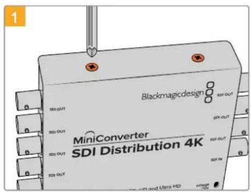
Using a philips head screwdriver, remove the four (M3) screws on the sides of Mini Converter SDI Distribution 4K.
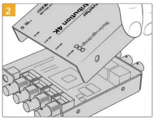
Slide off the external cover.
natural_image
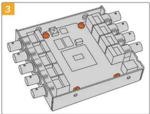
3D technical diagram of an electronic device casing with multiple ports and mounting holes (no text or symbols)Using a T10 torx screwdriver, remove the four screws connecting the circuit board to Mini Converter SDI Distribution 4K's frame.
natural_image
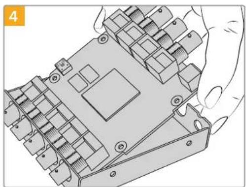
Technical illustration of a mechanical component with multiple slots and mounting holes, being handled by hands (no text or symbols)Gently pull the circuit board from the frame to access the USB connector.
natural_image
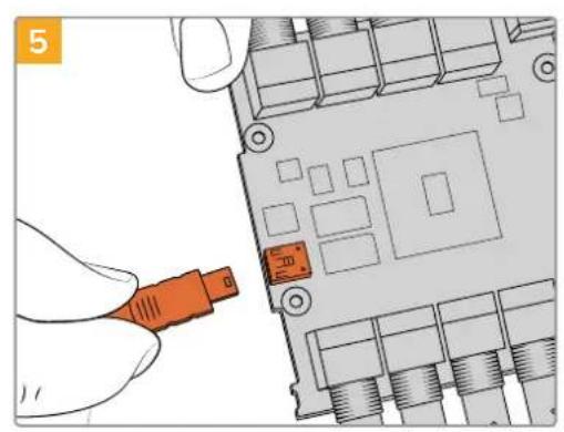
Illustration of a hand inserting an orange USB into a computer motherboard (no text or symbols visible)Plug in your Mini Converter SDI Distribution 4K's power supply and connect it to a computer using a USB cable. Update the internal software as you would any other mini converter.
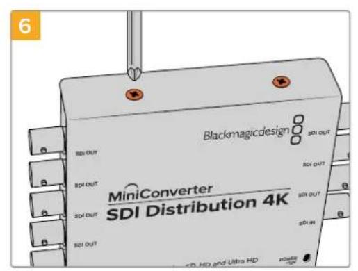
Repeat steps 1 - 4 in reverse to reassemble Mini Converter SDI Distribution 4K.
NOTE When handling your Mini Converter SDI Distribution 4K's circuit board, be careful to always hold it by the edges to prevent accidentally short circuiting internal components.
Changing Settings
If your Blackmagic Converter has adjustable settings, there are two ways you can change them. You can use the built in switches on the side of your converter, or you can change settings using the Blackmagic Converters Setup utility software. The utility is also used to change any settings that can't be set using the switches, for example analog video and audio levels.
Changing Settings using Switches
Many Blackmagic Converter models have built in switches.
To change a switch setting simply push the switch up or down using the tip of a pen. This turns the switches on or off. With 8 switches, this gives you many combinations so you can choose exactly the conversion settings you want.
You'll find a switch settings diagram printed on the base of your converter. Ensure your switch settings correspond to the legend by observing the switch numbers from 1 to 8, left to right.
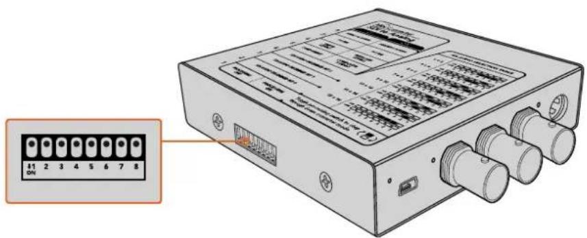
Change settings by adjusting the switches with a pen.
For a full description of the switches and their settings, refer to your converter model in this manual. Even though switch settings are printed on the base of your converter, new features in later updates can add new settings so it's worth checking the latest version of this manual for the most up to date information. You can download the latest version from the Blackmagic Design support center at www.blackmagicdesign.com/support.
Changing Settings using Blackmagic Converters Setup
Once Blackmagic Converters Setup is installed on your computer, connect the setup utility to your Blackmagic Converter via USB.
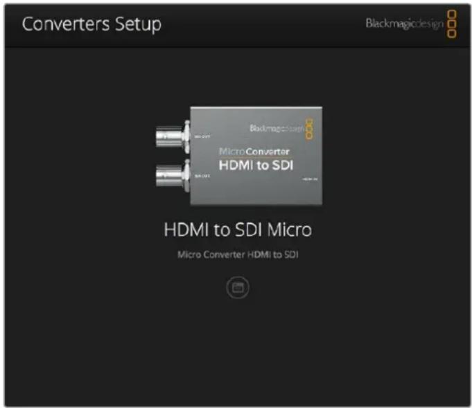
The Blackmagic Converters setup utility lets you update your converter's internal software and adjust settings using a Mac OS X or Windows computer.
The first thing you'll see when launching the software is the 'home' page. If you have more than one converter connected to your computer, select your desired converter by clicking the arrows on the left and right side of the Blackmagic Converters Setup home page.
To change settings, click on the 'settings' icon below the image of your Blackmagic Converter. Adjustments will be immediately saved to your converter. This means if power is lost, your settings will be reestablished as soon as power is restored.
Even though most settings are configured using the built in switches, some settings can only be set using the setup software, for example adjusting analog video or audio levels.
TIP Teranex Mini Converters are 12G-SDI converters that support even more video formats including up to 4K DCI 60p. If you are looking for information on how to use a Teranex Mini Converter, including how to change settings using the Blackmagic Teranex Setup utility, refer to the Teranex Mini Converters manual. You can download the most up to date manual from the Blackmagic Design support center at www.blackmagicdesign.com/support
About Tab
The ‘about’ tab in Blackmagic Converters Setup is common across all converter models. You can use the settings in this tab to name your Blackmagic Converter. Simply click in the ‘name’ text box and type your desired converter name. Click ‘save’ to confirm the change.
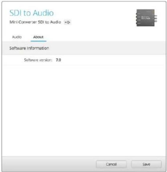
The 'about' tab in Blackmagic Converters Setup is used to name your Blackmagic Converter. You can also check the version of the setup software.
The 'Software Information' menu in the 'about' tab identifies which software version your Blackmagic Converter is running. If your converter's internal software is older than the current version that comes with Blackmagic Converters Setup, an update button will be present here that allows you to bring your converter's software up to date.
Blackmagic Converter Models
Blackmagic Converters provide conversion solutions for all types of conditions. For example, Mini Converters are tough and lightweight so you can mount them on video equipment or video trays, Battery Converters are super strong with a built in rechargeable battery so are portable and self powered and Blackmagic Micro Converters are tiny SDI to HDMI and HDMI to SDI converters that can be powered via USB so are perfect for attaching to monitors and laptop computers.
The following pages contain information about your Blackmagic Converter, plus switch settings and setup software settings.
Teranex Mini Converters
Blackmagic Teranex Mini Converters are 12G-SDI converters that support video formats up to 4K DCI 60p. These converters can be controlled using an optional Teranex Mini Smart Panel with built in LCD, buttons and a rotary knob, and can be powered via Ethernet. If you are looking for information about these converters, including controlling them via the Blackmagic Teranex Setup utility, refer to the Teranex Mini Converters manual which you can download from the Blackmagic Design support center at www.blackmagicdesign.com/support
Blackmagic Micro Converters
Micro Converter SDI to HDMI
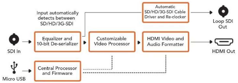
With Micro Converter SDI to HDMI you can connect a huge range of HDMI displays and video projectors to SDI based equipment. Your Micro Converter SDI to HDMI automatically detects between SD/HD/3G-SDI and converts to HDMI with embedded audio. This tiny broadcast quality converter is protected by a strong aluminum chassis and powers over USB, meaning you can power your Blackmagic Micro Converter via your laptop or television's USB connector using a common micro USB cable. Micro USB cables are used to connect some cell phones to chargers and laptops, so if you have one of these, you can use the same cable. If the USB connector on your cable is a different type, the correct cable can be purchased from most electronic equipment stores.
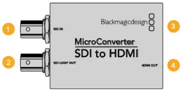
Connectors
1 SDI In
Primary SDI input BNC connector.
2 SDI Loop
Loop through output of your SDI input BNC connector.
3 Micro USB / Power
Provides power from the included adapter or any device capable of providing 5V via a standard USB to Micro USB cable, such as a laptop or television. Also connects to Blackmagic Converters Setup software via your Mac OS X or Windows Computer.
4 HDMI Out
HDMI type A video output.
Blackmagic Converters Setup Settings
The Blackmagic Converters Setup utility can be used to change settings and update your Micro Converter's software. You can access these settings by moving between the 'video' and 'about' tabs.
The ‘about’ tab is detailed in the ‘changing settings’ section in this manual.
The ‘video’ tab for Micro Converter SDI to HDMI contains the following settings.
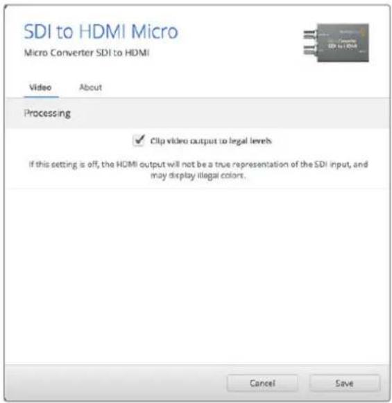
The 'clip video output to legal levels' setting is checked by default. This setting ensures your HDMI output is a true representation of the SDI input.
Processing menu
The ‘clip video output to legal levels’ checkbox controls clipping of your SDI input to ensure that it stays within HDMI legal levels and should be kept on by default.
Micro Converter SDI to HDMI Block Diagram
flowchart
graph LR
    A["SDI In"] --> B["Equalizer and 10-bit De-serializer"]
    C["Micro USB"] --> D["Central Processor and Firmware"]
    B --> E["Customizable Video Processor"]
    D --> E
    E --> F["HDMI Video and Audio Formatter"]
    G["Automatic SD/HD/3G-SDI Cable Driver and Re-clocker"] --> H["Loop SDI Out"]
    I["HDMI Out"] --> H
    B -.-> E
    D -.-> E
Micro Converter HDMI to SDI
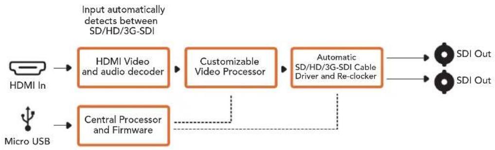
You can use Micro Converter HDMI to SDI to convert HDMI outputs from devices such as HDV cameras and game consoles to SDI. This means you can send video signals from HDMI over SDI using the longest SDI cables. You can even add SDI outputs to computers with HDMI compatibility. This tiny broadcast quality converter is protected by a strong aluminum chassis and powers over USB, meaning you can power your Blackmagic Micro Converter via your laptop or television's USB connector using a common micro USB cable. Micro USB cables are used to connect some cell phones to chargers and laptops, so if you have one of these, you can use the same cable. If the USB connector on your cable is a different type, the correct cable can be purchased from most electronic equipment stores.
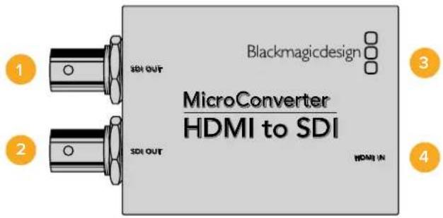
Connectors
1 SDI OUT
SDI video output BNC connector.
2 SDI OUT
Second SDI output.
3 Micro USB / Power
Provides power from the included adapter or any device capable of providing 5V via a standard USB to Micro USB cable, such as a laptop or television. Also connects to Blackmagic Converters Setup software via your Mac OS X or Windows Computer to update the Micro Converter's internal software.
4 HDMI In
HDMI type A video input.
Blackmagic Converters Setup Settings
The Blackmagic Converters Setup utility can be used to change settings and update your Micro Converter's software. You can access these settings by moving between the 'video,' and 'about' tabs.
The 'about' tab is detailed in the 'changing settings' section in this manual.
The 'video' tab for Micro Converter HDMI to SDI contains the following settings.
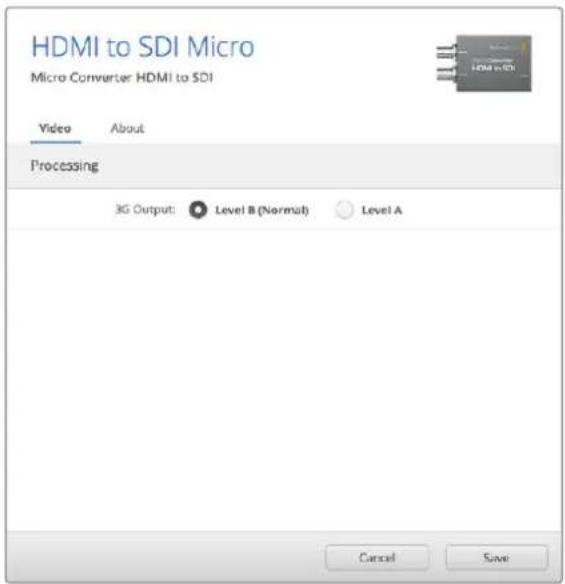
Use the 'video' tab in Blackmagic Converters Setup to toggle SDI levels.
Processing menu
The '3G Output' menu lets you select between Level A or Level B 3G-SDI. This setting lets you change the 3G-SDI output standard to maintain compatibility with equipment that can only receive level A or level B 3G-SDI video. Level B is the default setting.
Micro Converter HDMI to SDI Block Diagram
flowchart
graph LR
    A["HDMI In"] --> B["HDMI Video and audio decoder"]
    C["Micro USB"] --> D["Central Processor and Firmware"]
    B --> E["Customizable Video Processor"]
    D --> E
    E --> F["Automatic SD/HD/3G-SDI Cable Driver and Re-clocker"]
    F --> G["SDI Out"]
    F --> H["SDI Out"]
    style A fill:#f9f,stroke:#333
    style C fill:#f9f,stroke:#333
    style B fill:#ccf,stroke:#333
    style D fill:#ccf,stroke:#333
    style E fill:#ccf,stroke:#333
    style F fill:#cfc,stroke:#333
    style G fill:#fcc,stroke:#333
    style H fill:#fcc,stroke:#333
Micro Converter BiDirectional SDI/HDMI
Micro Converter BiDirectional SDI/HDMI converts SD and HD video from HDMI to SDI, and SDI to HDMI with embedded audio simultaneously. For example, you can convert the HDMI output from an HDV camera to SDI for longer cable lengths, while also converting an SDI return feed to HDMI so you can connect to an HDMI TV.
If you have only one input connected, the SDI and HDMI outputs both become loop outputs so you can feed the input signal to other HDMI and SDI equipment.
Your Micro Converter BiDirectional SDI/HDMI automatically detects SD/HD/3G-SDI input format and sets the output format to match.
This tiny broadcast quality converter is protected by a strong aluminum chassis. It is powered over USB, meaning you can power your Blackmagic Micro Converter BiDirectional SDI/HDMI from your laptop or television's USB connector using a common micro USB cable. Micro USB cables are used to connect some cell phones to chargers and laptops, so if you have one of these, you can use the same cable. If the USB connector on your cable is a different type, the correct cable can be purchased from most electronic equipment stores.
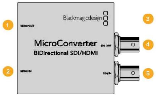
Connectors
1 HDMI Out
HDMI type A video output.
2 HDMI In
HDMI type A video input.
3 Micro USB / Power
Provides 5V power from any device capable of providing 5V via a standard USB to Micro USB cable, such as a laptop or television. Also connects to Blackmagic Converters Setup software via your Mac OS X or Windows Computer.
4 SDI Out
SDI video output BNC connector.
5 SDI In
SDI video input BNC connector.
Blackmagic Converters Setup Settings
The Blackmagic Converters Setup utility can be used to change settings and update your Micro Converter's software. You can access these settings by moving between the 'video,' and 'about' tabs.
The 'About' tab is described in the 'Changing Settings' section in this manual.
The 'Video' tab for Micro Converter BiDirectional SDI/HDMI contains the following settings.
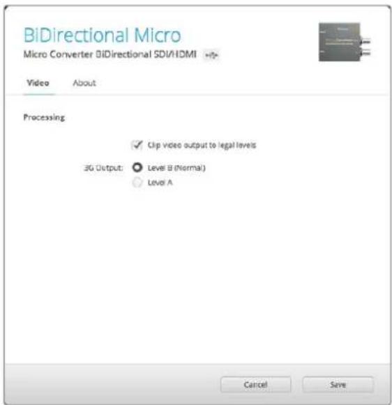
The 'Clip video output to legal levels' setting is checked by default. This setting makes sure your HDMI output is a true representation of the SDI input.
Processing menu
The ‘Clip video output to legal levels’ checkbox controls clipping of your SDI input to ensure that it stays within HDMI legal levels and should be kept on by default.
The '3G Output' setting lets you select between Level A or Level B 3G-SDI. This changes the 3G-SDI output standard to maintain compatibility with equipment that can receive only level A or level B 3G-SDI video. The default setting is Level B.
Micro Converter BiDirectional SDI/HDMI Block Diagram
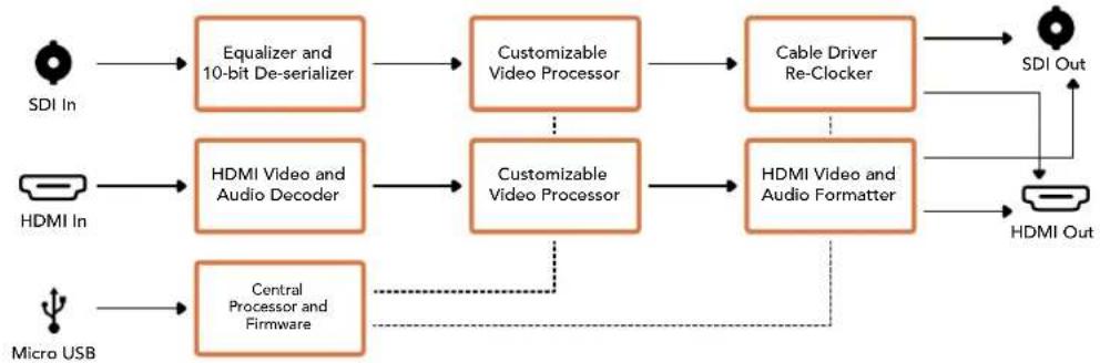
flowchart
graph LR
    A["SDI In"] --> B["Equalizer and 10-bit De-serializer"]
    C["HDMI In"] --> D["HDMI Video and Audio Decoder"]
    E["Micro USB"] --> F["Central Processor and Firmware"]
    B --> G["Customizable Video Processor"]
    D --> H["Customizable Video Processor"]
    F --> I["HDMI Video and Audio Formatter"]
    G --> J["Cable Driver Re-Clocker"]
    H --> J
    I --> K["SDI Out"]
    J --> L["HDMI Out"]
    style A fill:#f9f,stroke:#333
    style C fill:#f9f,stroke:#333
    style E fill:#f9f,stroke:#333
Blackmagic Mini Converters
Mini Converter SDI to HDMI
Mini Converter SDI to HDMI can connect a huge range of HDMI displays and video projectors to SDI based equipment. Your Mini Converter SDI to HDMI automatically detects between SD/HD/3G-SDI and converts to HDMI with embedded audio, plus balanced AES/EBU or analog audio out.
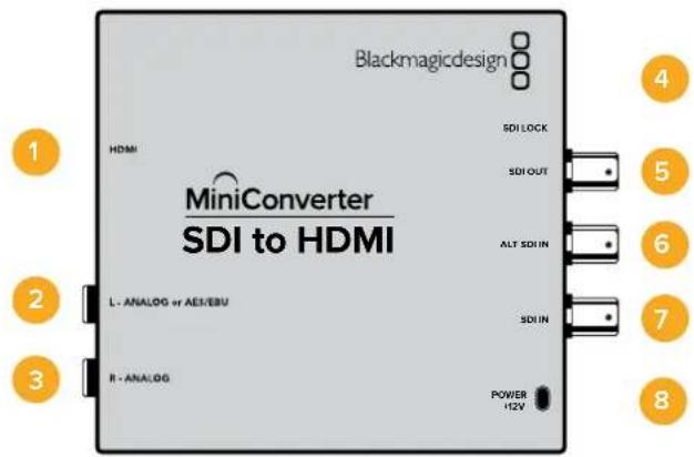
Connectors
1 HDMI
HDMI type A video output.
2 L - ANALOG or AES/EBU
Balanced left channel analog audio, or AES/EBU digital audio output on a 1/4" jack connector.
3 R - ANALOG
Balanced right channel analog audio output 1/4" jack connector.
4 MINI-B USB PORT
Connects to the Converters Setup software via your Mac OS X or Windows computer. The Mini Converter's internal software is also updated using the USB port.
5 SDI OUT
SDI video output on a BNC connector.
6 ALT SDI IN
Redundant SDI input is provided as an optional back up.
7 SDI IN
Primary SDI input.
8 POWER +12V
12 volt power supply input.
Switches
Switch 8 - Analog Audio, AES/EBU Audio
Set switch 8 to OFF to select balanced analog audio, or to ON for digital AES/EBU audio output.
Switch 4 - SDI Audio De-Embed Bit 2
Switches 4, 3 and 2 are grouped together to provide 8 ON/OFF combinations. Having eight different combinations allows eight independent pairs of audio channels to be de-embedded from your SDI input and output to HDMI, analog or AES/EBU audio.
Switch 3 - SDI Audio De-Embed Bit 1
See switch 4 description.
Switch 2 - SDI Audio De-Embed Bit 0
See switch 4 description.
Switch 1 - Processing Off - Processing On
This switch is not used.
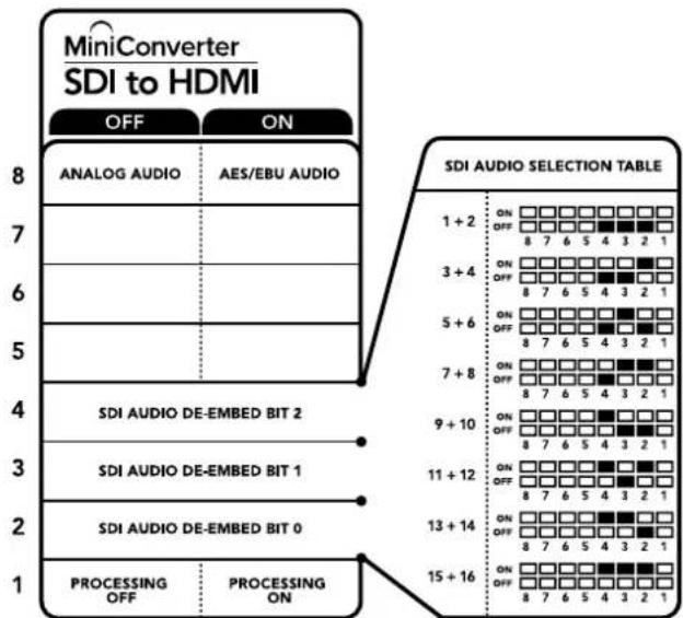
The switch legend on the base of your converter gives you all the information you need to change conversion settings.
Mini Switch Settings Example
Experiment with the switches by setting your Blackmagic Mini Converter to de-embed SDI audio channels 1 and 2 and output to analog by setting switches 8, 4, 3 and 2 to the OFF position.
SDI Audio Selection Table
| Audio Channels | Switch 4 | Switch 3 | Switch 2 | Switch Diagram |
| 1 and 2 | OFF | OFF OFF | 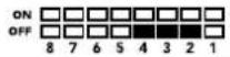 | |
| 3 and 4 OFF OFF ON | 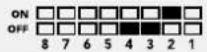 | |||
| 5 and 6 OFF ON OFF | 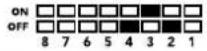 | |||
| 7 and 8 OFF ON ON | 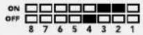 | |||
| 9 and 10 ON OFF OFF | 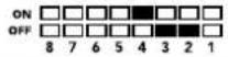 | |||
| 11 and 12 ON OFF ON | 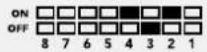 | |||
| 13 and 14 ON ON OFF | 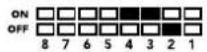 | |||
| 15 and 16 ON ON ON | 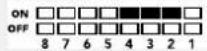 |
Blackmagic Converters Setup Settings
The Converters Setup utility can be used to change settings and update your Mini Converter's software. You can access these settings by moving between the 'video,' 'audio,' and 'about' tabs.
The 'about' tab is detailed in the 'changing settings' section in this manual.
The 'video' tab for Mini Converter SDI to HDMI contains the following settings.
Processing menu
The ‘clip video output to legal levels’ checkbox controls clipping of your SDI input to ensure that it stays within HDMI legal levels and should be kept on by default.
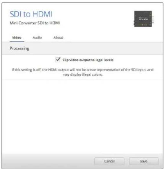
The 'clip video to legal levels' setting is checked by default. This ensures that your HDMI video output stays within legal levels.
The 'audio' tab for Mini Converter SDI to HDMI contains the following settings.
Output Levels menu
This menu allows you to adjust the gain on the audio output. You can adjust audio levels independently per channel, or together by clicking the 'link' icon next to their sliders. To reset all audio levels back to 0 dB click the 'reset' button at the top of the 'output levels' menu.
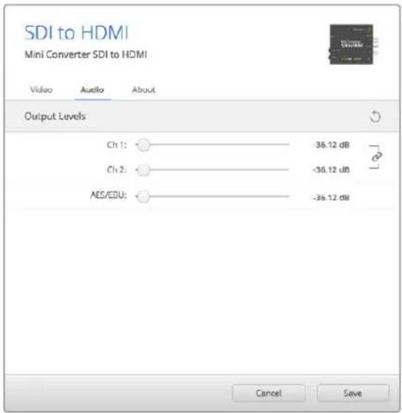
Use the 'audio' tab in Converters Setup to adjust audio levels.
Mini Converter SDI to HDMI Block Diagram
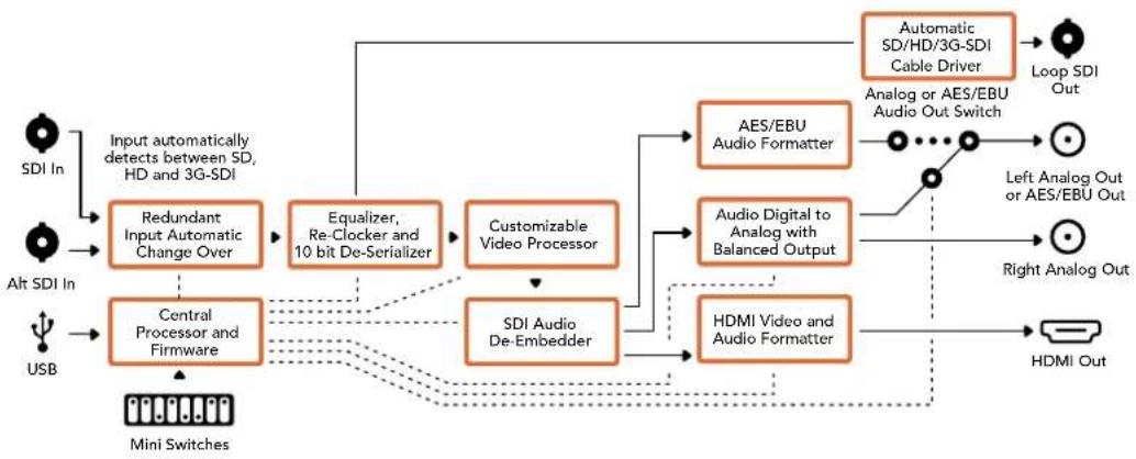
flowchart
graph TD
    A["Input automatically detects between SD, HD and 3G-SDI"] --> B["Redundant Input Automatic Change Over"]
    C["Alt SDI In"] --> D["Central Processor and Firmware"]
    E["USB"] --> D
    B --> F["Equalizer, Re-Clocker and 10 bit De-Serializer"]
    D --> G["Customizable Video Processor"]
    G --> H["SDI Audio De-Embedder"]
    H --> I["HDMI Video and Audio Formatter"]
    I --> J["Automatic SD/HD/3G-SDI Cable Driver"]
    J --> K["Loop SDI Out"]
    I --> L["AES/EBU Audio Formatter"]
    I --> M["Audio Digital to Analog with Balanced Output"]
    L --> N["Analog or AES/EBU Audio Out Switch"]
    M --> O["Left Analog Out or AES/EBU Out"]
    N --> P["Right Analog Out"]
    O --> Q["HDMI Out"]
    R["Mini Switches"] --> D
Mini Converter SDI to HDMI 4K
With Mini Converter SDI to HDMI 4K and the SDI to HDMI 4K Heavy Duty model, you can connect a huge range of HDMI displays and video projectors to SDI based equipment. Your Mini Converter SDI to HDMI 4K automatically detects between SD/HD/3G/6G-SDI and converts to HDMI with embedded audio, plus balanced AES/EBU or analog audio out. The HDMI instant lock feature lets you lock the HDMI output so that changing sources using the same format is clean and glitch free. If your converter detects an HD monitor or TV connected to the HDMI output and has Ultra HD connected to the SDI input, the Ultra HD source will be automatically down converted so you can view the Ultra HD source on an HD monitor.
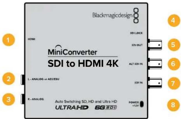
Connectors
1 HDMI
HDMI type A video output.
2 L - ANALOG or AES/EBU
Balanced left channel analog audio, or AES/EBU digital audio output 1/4" jack connector.
3 R - ANALOG
Balanced right channel analog audio output 1/4" jack connector.
4 MINI-B USB PORT
Connects to the Converters Setup software via your Mac OS X or Windows computer. The Mini Converter's internal software is also updated using the USB port.
5 SDI OUT
SDI video output BNC connector.
6 ALT SDI IN
Redundant SDI input is provided as an optional back up.
7 SDI IN
Primary SDI input.
8 POWER +12V
12 volt power supply input.
Switches
TIP On the Mini Converter Heavy Duty model, the switches are protected by a rubber dust cover. Simply lift the edge of the cover to access the switches.
Mini Converter SDI to HDMI 4K's switches provide the following settings:
Switch 8 - Analog Audio, AES/EBU Audio
Set switch 8 to OFF to select balanced analog audio, or to ON for digital AES/EBU audio output.
Switch 4 - SDI Audio De-Embed Bit 2
Switches 4, 3 and 2 are grouped together to provide 8 ON/OFF combinations. Having eight different combinations allows eight independent pairs of audio channels to be de-embedded from your SDI input and output to HDMI, analog or AES/EBU audio.
Switch 3 - SDI Audio De-Embed Bit 1
See switch 4 description.
Switch 2 - SDI Audio De-Embed Bit 0
See switch 4 description.
Switch 1 - Processing Off - Processing On
This switch is not used.
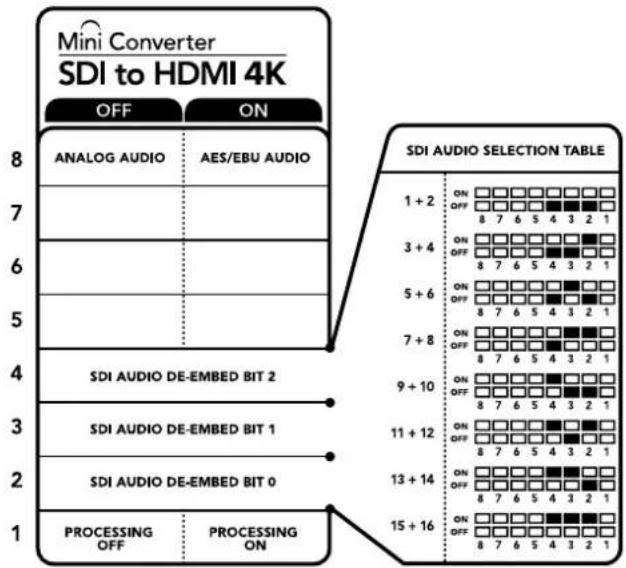
The switch legend on the base of your converter gives you all the information you need to change conversion settings.
Mini Switch Settings Example
Experiment with the switches by setting your Blackmagic Mini Converter to de-embed SDI audio channels 1 and 2 and output to analog by setting switches 8, 4, 3 and 2 to the OFF position.
SDI Audio Selection Table
| Audio Channels Switch 4 Switch 3 Switch 2 Switch Diagram | |||
| 1 and 2 OFF OFF OFF | ONOFF8 7 6 5 4 3 2 1 | ||
| 3 and 4 OFF OFF ON | ONOFF8 7 6 5 4 3 2 1 | ||
| 5 and 6 OFF ON OFF | ONOFF8 7 6 5 4 3 2 1 | ||
| 7 and 8 OFF ON ON | ONOFF8 7 6 5 4 3 2 1 | ||
| 9 and 10 ON OFF OFF | ONOFF8 7 6 5 4 3 2 1 | ||
| 11 and 12 ON OFF ON | ONOFF8 7 6 5 4 3 2 1 | ||
| 13 and 14 ON ON OFF | ONOFF8 7 6 5 4 3 2 1 | ||
| 15 and 16 | ON ON ON | ONOFF8 7 6 5 4 3 2 1 | |
Blackmagic Converters Setup Settings
The Converters Setup utility can be used to change settings and update your Mini Converter's software. You can access these settings by moving between the 'video,' 'audio,' and 'about' tabs.
The ‘about’ tab is detailed in the ‘changing settings’ section in this manual.
The 'video' tab for Mini Converter SDI to HDMI 4K contains the following settings.
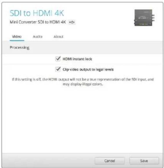
The 'clip video to legal levels' setting is checked by default. This ensures that your HDMI video output stays within legal levels.
Processing menu
- HDMI Instant Lock
Select this checkbox to enable the HDMI instant lock feature. When HDMI instant lock is enabled, the HDMI output signal is kept active even when changing sources. This means your converter does not have to wait for the HDMI television or monitor to lock before displaying the video output as the HDMI signal is already locked. It's important to note that this feature only works when changing sources using the same video standard.
The HDMI instant lock feature can introduce a small delay in video and audio, so if you need zero delay in your converted output you can bypass the HDMI instant lock feature by deselecting the checkbox.
- Clip Video Output to Legal Levels
This checkbox controls clipping of your SDI input to ensure that it stays within HDMI legal levels and should be kept on by default.
Output Levels menu
This menu allows you to adjust the gain on the audio output. You can adjust audio levels independently per channel, or together by clicking the 'link' icon next to their sliders. To reset all audio levels back to 0 dB click the 'reset' button at the top of the 'output levels' menu.
The 'audio' tab for Mini Converter SDI to HDMI 4K contains the following settings.
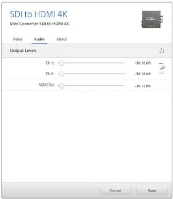
Use the 'audio' tab in Converters Setup to adjust audio levels.
Mini Converter SDI to HDMI 4K Block Diagram
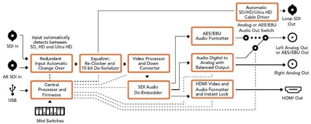
flowchart
graph TD
    A["Input automatically detects between SD, HD and Ultra HD"] --> B["Redundant Input Automatic Change Over"]
    C["Alt SDI In"] --> D["Central Processor and Firmware"]
    E["USB"] --> D
    B --> F["Equalizer, Re-Clocker and 10 bit De-Serializer"]
    D --> G["Video Processor and Down Converter"]
    G --> H["SDI Audio De-Embedder"]
    H --> I["AES/EBU Audio Formatter"]
    H --> J["Audio Digital to Analog with Balanced Output"]
    I --> K["Automatic SD/HD/Ultra HD Cable Driver"]
    J --> K
    K --> L["Loop SDI Out"]
    K --> M["Left Analog Out or AES/EBU Out"]
    K --> N["Right Analog Out"]
    K --> O["HDMI Out"]
    P["Mini Switches"] --> D
    Q["Input"] --> A
    R["Input"] --> C
Mini Converter SDI to HDMI 6G
With Mini Converter SDI to HDMI 6G, you can connect a huge range of HDMI displays and video projectors to SDI based equipment. Your Mini Converter SDI to HDMI 6G automatically detects between SD SDI, HD-SDI, 3G-SDI and 6G-SDI input sources and converts to HDMI with embedded audio, plus balanced AES/EBU or analog audio out.
The HDMI instant lock feature lets you lock the HDMI output so that changing sources using the same format is clean and glitch free. If your converter detects an HD monitor or TV connected to the HDMI output and has Ultra HD connected to the SDI input, the Ultra HD source will be automatically down converted so you can view the Ultra HD source on an HD monitor.
You can also load 3D LUTs for adding looks, grades, and color profiles to your converted output. The 3D LUT is a full 33 point hardware lookup table for greater accuracy with color manipulation and can even be used to accurately color calibrate consumer televisions so they can be used for critical color correction work. The 3D LUT also allows color space conversions so different color spaces can be used with various displays. Your Mini Converter SDI to HDMI 6G comes with two default LUTs, including color to monochrome and Blackmagic camera default color space to REC 709.
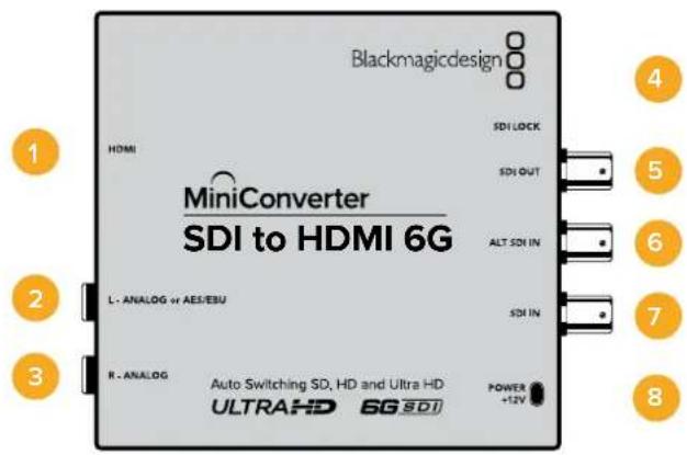
Connectors
1 HDMI
HDMI type A video output.
2 L - ANALOG or AES/EBU
Balanced left channel analog audio, or AES/EBU digital audio output 1/4" jack connector.
3 R - ANALOG
Balanced right channel analog audio output 1/4" jack connector.
4 MINI-B USB PORT
Connects to the Converters Setup software via your Mac OS X or Windows computer. The Mini Converter's internal software is also updated using the USB port.
5 SDI OUT
SDI video output BNC connector
6 ALT SDI IN
Redundant SDI input is provided as an optional back up.
7 SDI IN
Primary SDI input.
8 POWER +12V
12 volt power supply input.
Switches
Mini Converter SDI to HDMI 6G's switches provide the following settings:
Switch 8 - Analog Audio, AES/EBU Audio
Set switch 8 to OFF to select balanced analog audio, or to ON for digital AES/EBU audio output.
Switch 7 - LUT Off, LUT On
Set Switch 7 to OFF to disable the LUT, or to ON to enable the LUT.
Switch 6 - LUT 1, LUT2
Set Switch 6 to OFF to select LUT 1, or to ON to select LUT 2.
Switch 5 - LUT On Loop Off, LUT On Loop On
Set Switch 5 to OFF to select LUT On Loop Off, or to ON to select LUT On Loop On.
Switch 4 - SDI Audio De-Embed Bit 2
Switches 4, 3 and 2 are grouped together to provide 8 ON/OFF combinations. Having eight different combinations allows eight independent pairs of audio channels to be de-embedded from your SDI input and output to HDMI, analog or AES/EBU audio.
Switch 3 - SDI Audio De-Embed Bit 1
See switch 4 description.
Switch 2 - SDI Audio De-Embed Bit 0
See switch 4 description.
Switch 1 - HDMI Instant Lock Off, HDMI Instant Lock On
Set switch 1 to OFF to select HDMI Instant Lock Off, or to ON to select HDMI Instant Lock On.
When HDMI instant lock is enabled, the HDMI output signal is kept active even when changing sources. This means your converter does not have to wait for the HDMI television or monitor to lock before displaying the video output as the HDMI signal is already locked. It's important to note that this feature only works when changing sources using the same video standard.
The HDMI instant lock feature can introduce a small delay in video and audio, so if you need zero delay in your converted output you can bypass the HDMI instant lock feature by turning HDMI Instant Lock OFF.
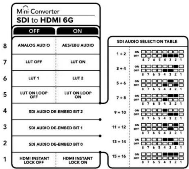
The switch legend on the base of your converter gives you all the information you need to change conversion settings
Mini Switch Settings Example
Experiment with the switches by setting your Blackmagic Mini Converter to de-embed SDI audio channels 1 and 2 and output to analog by setting switches 8, 4, 3 and 2 to the OFF position.
SDI Audio Selection Table
| Audio Channels Switch 4 Switch 3 Switch 2 Switch Diagram | ||
| 1 and 2 OFF OFF OFF | 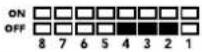 | |
| 3 and 4 OFF OFF ON | 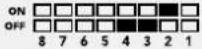 | |
| 5 and 6 OFF ON OFF | 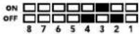 | |
| 7 and 8 OFF ON ON | 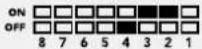 | |
| 9 and 10 ON OFF OFF | 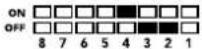 | |
| 11 and 12 ON OFF ON | 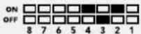 | |
| 13 and 14 ON ON OFF | 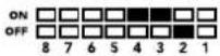 | |
| 15 and 16 ON ON ON | 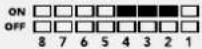 | |
Blackmagic Converters Setup Settings
The Converters Setup utility can be used to change settings and update your Mini Converter's software. You can access these settings by moving between the 'video,' 'audio,' and 'about' tabs. The 'about' tab is detailed in the 'changing settings' section in this manual.
The 'video' tab for Mini Converter SDI to HDMI 6G contains the following settings.
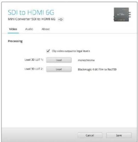
The 'clip video output to legal levels' setting is checked by default. This ensures that your HDMI video output stays within legal levels.
Processing menu
- 33 Point 3D LUT
Your Mini Converter SDI to HDMI 6G supports .cube LUT files that can be created using DaVinci Resolve software, or other color correction software that can export .cube files.
You can load 2 separate LUTs by clicking on the 'load' button for each LUT slot, selecting the desired .cube file from your computer, and clicking 'OK'. Click 'save' to confirm your settings. The LUT filename will appear next to each 'load' button so you know which LUT is being used for LUT 1 or LUT 2.
- What is a 3D LUT?
A 3D LUT, or '3D Lookup Table', is a file containing table of values that are used to modify the video colorspace to a new set of color values in a 3D cube space.
The color cube contains all the variations between the mix of each primary color, defined within three x, y, z spatial dimensions. This means the RGB channels in the SDI input video can be remapped to any other RGB output color in the HDMI video output. This is very powerful as it means any color can be mapped to any other color so you can perform very precise color adjustments for calibrating displays, or loading log gamma curves for display when working with different types of raw camera files on set where you want to see linear gamma.
To show how powerful 3D LUTs can be, one of the default LUTs loaded can convert your input video to black and white. This shows that all the input RGB colors are remapped via the 3D LUT to black and white RGB output values via the HDMI output. You can create your own 3D LUTs and upload them via the admin software and DaVinci Resolve even allows you to convert a color grade setting to a 3D LUT that you can then upload to your Mini Converter SDI to HDMI 6G. You can output the 3D LUT on the SDI video loop output so you could even use your Mini Converter as a dedicated 3D LUT color processor even if you don't use the HDMI output!
For more information on how to create a 3D LUT .cube file, refer to the DaVinci Resolve manual which you can download from the Blackmagic Design website at www.blackmagicdesign.com/support.
- Clip Video Output to Legal Levels
This checkbox controls clipping of your SDI input to ensure that it stays within HDMI legal levels and should be kept on by default.
Output Levels menu
This menu allows you to adjust the gain on the audio output. You can adjust audio levels independently per channel, or together by clicking the 'link' icon next to their sliders. To reset all audio levels back to 0 dB click the 'reset' button at the top of the 'output levels' menu. The 'audio' tab for Mini Converter SDI to HDMI 6G contains the following settings.
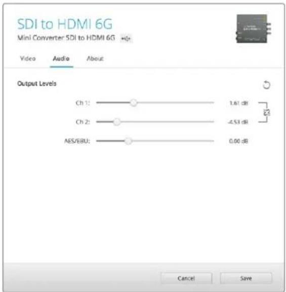
Use the 'audio' tab in Converters Setup to adjust audio levels
Mini Converter SDI to HDMI 6G Block Diagram
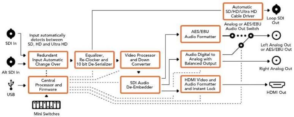
flowchart
graph TD
    A["SDI In"] --> B["Input automatically detects between SD, HD and Ultra HD"]
    C["Alt SDI In"] --> D["Central Processor and Firmware"]
    E["USB"] --> D
    B --> F["Redundant Input Automatic Change Over"]
    D --> G["Video Processor and Down Converter"]
    F --> H["Equalizer, Re-Clocker and 10 bit De-Serializer"]
    G --> I["Video Processor and Down Converter"]
    H --> J["AES/EBU Audio Formatter"]
    I --> K["Audio Digital to Analog with Balanced Output"]
    J --> L["AO/AOS"]
    K --> M["HDMI Video and Audio Formatter and Instant Lock"]
    L --> N["Automatic SD/HD/Ultra HD Cable Driver"]
    M --> O["Loop SDI Out"]
    N --> P["Loop SDI Out"]
    Q["Mini Switches"] --> D
    R["Analog or AES/EBU Audio Out Switch"] --> S["Left Analog Out or AES/EBU Out"]
    T["Right Analog Out"] --> U["HDMI Out"]
Mini Converter HDMI to SDI
Your Mini Converter HDMI to SDI can convert HDMI outputs from devices such as HDV cameras and game consoles to SDI with the choice to embed audio from HDMI, AES/EBU or balanced analog audio inputs. This means you can send video signals from HDMI over SDI using the longest SDI cables. You can even add SDI outputs to computers with HDMI compatibility. This converter also includes HD to SD down conversion.
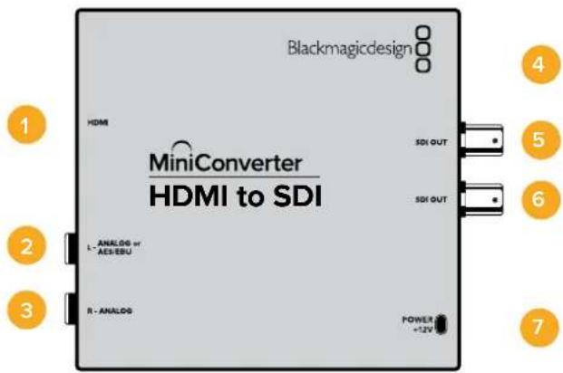
Connectors
1 HDMI
HDMI type A video input.
2 L - ANALOG or AES/EBU
Balanced left channel analog audio or AES/EBU digital audio input on a 1/4" jack connector.
3 R - ANALOG
Balanced right channel analog audio input 1/4" jack connector.
4 MINI-B USB PORT
Connects to the Converters Setup software via your Mac OS X or Windows computer. The Mini Converter's internal software is also updated using the USB port.
5 SDI OUT
SDI video output on a BNC connector.
6 SDI OUT
Second SDI output.
7 POWER +12V
12 volt power supply input.
Switches
Mini Converter HDMI to SDI's switches provide the following settings:
Switch 8 - Analog Audio, AES/EBU Audio
Set switch 8 to OFF to select balanced analog audio, or to ON for digital AES/EBU audio input. To use these inputs Switch 7 must also be set to ON.
Switch 7 - HDMI Audio - Input Audio
Set switch 7 to OFF to select embedded HDMI audio, or to ON for analog or AES/EBU audio.
Switch 1 - Processing Off - Processing On
Down convert HD to SD with 3 types of aspect ratios by cycling through switch 1. For example, each time you cycle between OFF and On you apply anamorphic, center cut or letterbox aspect ratios. Leaving switch 1 set to OFF bypasses the down converter and outputs in HD.
When connected to the Blackmagic Converters Setup via USB, your down conversion settings are controlled by the software. If you want the converter to remember your software settings, disconnect from the computer, power cycle your converter and set your down conversion using mini switch 1.
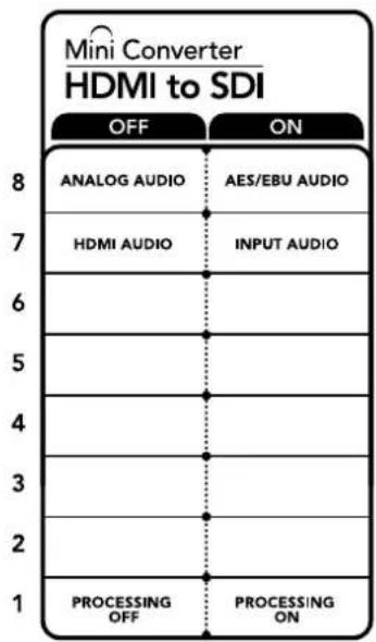
The switch legend on the base of your converter gives you all the information you need to change conversion settings.
Blackmagic Converters Setup Settings
The Converters Setup utility can be used to change settings and update your Mini Converter's software. You can access these settings by moving between the 'video,' 'audio,' and 'about' tabs.
The ‘about’ tab is detailed in the ‘changing settings’ section in this manual.
The 'video' tab for Mini Converter HDMI to SDI contains the following settings.
Processing menu
This menu lets you select the aspect ratio of content that is down converted from HD to SD. The options are 'letterbox,' 'anamorphic,' 'center cut', or 'off.'
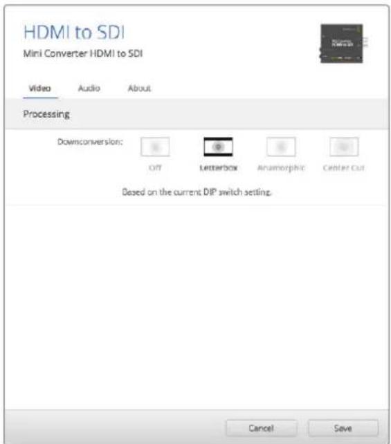
Use the 'video' tab In Converters Setup adjust processing settings.
The 'audio' tab for Mini Converter HDMI to SDI contains the following settings.
Input Levels menu
This menu allows you to adjust the gain on the audio input. You can adjust audio levels independently per channel, or together by clicking the 'link' icon next to their sliders. To reset all audio levels back to 0 dB click the 'reset' button at the top of the 'input levels' menu.
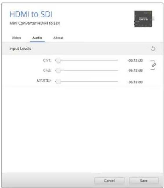
Use the 'audio' tab in Converters Setup to adjust audio levels.
Mini Converter HDMI to SDI Block Diagram
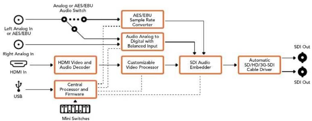
flowchart
graph TD
    A["Left Analog In or AES/EBU"] --> B["Analog or AES/EBU Audio Switch"]
    C["Right Analog In"] --> D["HDMI In"]
    E["USB"] --> F["Central Processor and Firmware"]
    B --> G["AES/EBU Sample Rate Converter"]
    D --> H["HDMI Video and Audio Decoder"]
    F --> I["Customizable Video Processor"]
    G --> J["SDI Audio Embedder"]
    H --> J
    I --> J
    J --> K["Automatic SD/HD/3G-SDI Cable Driver"]
    K --> L["SDI Out"]
    G --> M["Audio Analog to Digital with Balanced Input"]
    H --> N["Mini Switches"]
    I --> O["DSI Out"]
Mini Converter HDMI to SDI 4K
Your Mini Converter HDMI to SDI 4K and the HDMI to SDI 4K Heavy Duty model can convert HDMI outputs from devices such as HDV cameras and game consoles to SDI with the choice to embed audio from HDMI, AES/EBU or balanced analog audio inputs. This means you can send video signals from HDMI over SDI using the longest SDI cables. You can even add SDI outputs to computers with HDMI compatibility.
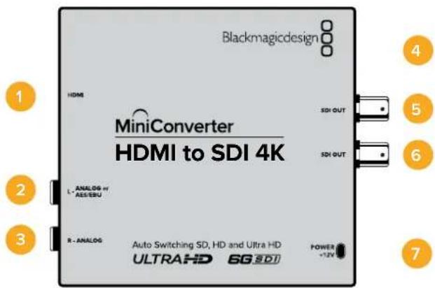
Connectors
1 HDMI
HDMI type A video input.
2 L - ANALOG or AES/EBU
Balanced left channel analog audio or AES/EBU digital audio input 1/4" jack connector.
3 R - ANALOG
Balanced right channel analog audio input 1/4" jack connector.
4 MINI-B USB PORT
Connects to the Converters Setup software via your Mac OS X or Windows computer. The Mini Converter's internal software is also updated using the USB port.
5 SDI OUT
SDI video output BNC connector.
6 SDI OUT
Second SDI output.
7 POWER +12V
12 volt power supply input.
Switches
TIP On the Mini Converter Heavy Duty model, the switches are protected by a rubber dust cover. Simply lift the edge of the cover to access the switches.
Mini Converter HDMI to SDI 4K's switches provide the following settings:
Switch 8 - Analog Audio, AES/EBU Audio
Set switch 8 to OFF to select balanced analog audio, or to ON for digital AES/EBU audio input. To use these inputs Switch 7 must also be set to ON.
Switch 7 - HDMI Audio - Input Audio
Set switch 7 to OFF to select embedded HDMI audio, or to ON for analog or AES/EBU audio.
Switches 2, 1 - Select Format Bit 1,0
When connecting an HDMI source that can output Ultra HD and HD, you can set your converter to force the source output to one or the other. This can be helpful when you want to record or display your computer's desktop on SDI equipment in HD so it is larger and easy to view.
While it may appear like it's an up or down conversion setting, what your converter is actually doing is telling your source equipment to output Ultra HD or HD video so that your converter can then output the source video's native HD or Ultra HD resolution without up or down conversion.
To force your source video to HD, Ultra HD, or to let your converter automatically negotiate the optimum resolution with your source equipment, simply use combinations of switches 1 and 2.
The combination settings are shown below.
AUTO - switch 1 to OFF, switch 2 to OFF.
Your converter will negotiate an optimum HD or Ultra HD resolution with your source equipment based on its output capabilities.
FORCE TO HD - switch 1 to OFF, switch 2 to ON.
If your HDMI source equipment is capable of outputting HD and Ultra HD, your converter will instruct the source equipment to output HD video.
FORCE TO ULTRA HD - Switch 1 to ON, Switch 2 to OFF.
If your HDMI source equipment is capable of outputting HD and Ultra HD, your converter will instruct the source to output Ultra HD video.
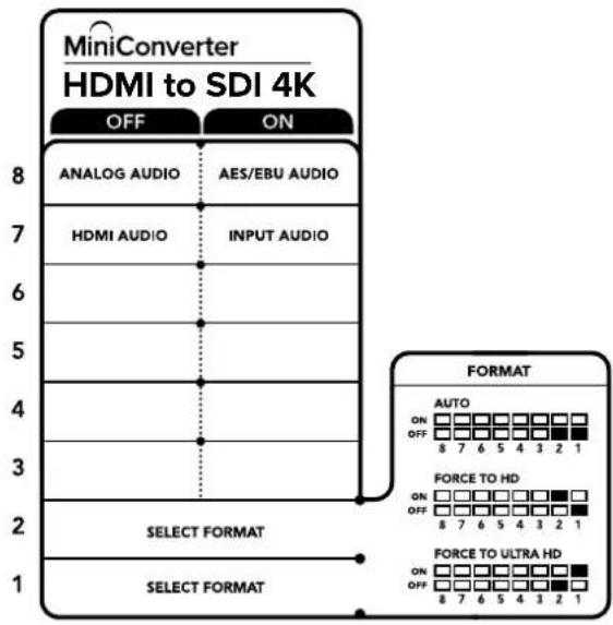
The switch legend on the base of your converter gives you all the information you need to change conversion settings.
Blackmagic Converters Setup Settings
The Converters Setup utility can be used to change settings and update your Mini Converter's software. You can access these settings by moving between the 'audio,' and 'about' tabs.
The ‘about’ tab is detailed in the ‘changing settings’ section in this manual.
The 'audio' tab for Mini Converter HDMI to SDI 4K contains the following settings.
Input Levels menu
This menu allows you to adjust the gain on the audio input. You can adjust audio levels independently per channel, or together by clicking the 'link' icon next to their sliders. To reset all audio levels back to 0 dB click the 'reset' button at the top of the 'input levels' menu.
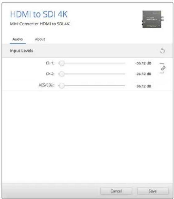
Use the 'audio' tab in Converters Setup to adjust audio levels.
Mini Converter HDMI to SDI 4K Block Diagram
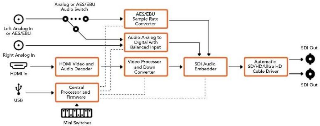
flowchart
graph TD
    A["Left Analog In or AES/EBU"] --> B["Analog or AES/EBU Audio Switch"]
    C["Right Analog In"] --> D["HDMI In"]
    E["USB"] --> F["Central Processor and Firmware"]
    B --> G["AES/EBU Sample Rate Converter"]
    D --> H["HDMI Video and Audio Decoder"]
    F --> I["Video Processor and Down Converter"]
    G --> J["SDI Audio Embedder"]
    H --> J
    I --> J
    J --> K["Automatic SD/HD/Ultra HD Cable Driver"]
    L["SDI Out"] --> K
    M["SDI Out"] --> K
    N["Mini Switches"] --> F
    style A fill:#f9f,stroke:#333
    style C fill:#f9f,stroke:#333
    style E fill:#f9f,stroke:#333
    style N fill:#ccf,stroke:#333
Mini Converter HDMI to SDI 6G
Your Mini Converter HDMI to SDI 6G can convert HDMI outputs from devices such as HDV cameras and game consoles to SDI with the choice to embed audio from HDMI, AES/EBU or balanced analog audio inputs. This means you can send video signals from HDMI over SDI using the longest SDI cables. You can even add SDI outputs to computers with HDMI compatibility.
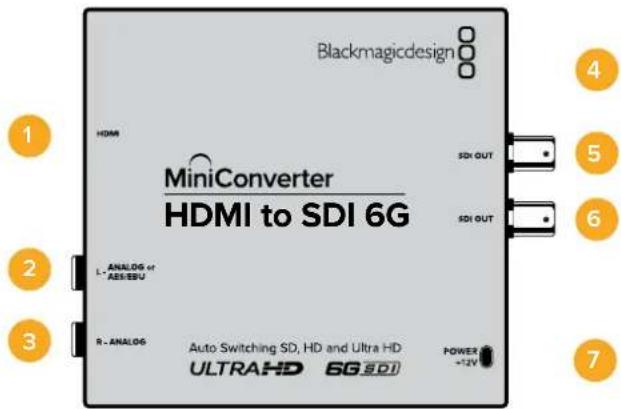
Connectors
1 HDMI
HDMI type A video input.
2 L - ANALOG or AES/EBU
Balanced left channel analog audio or AES/EBU digital audio input 1/4" jack connector.
3 R - ANALOG
Balanced right channel analog audio input 1/4" jack connector.
4 MINI-B USB PORT
Connects to the Converters Setup software via your Mac OS X or Windows computer. The Mini Converter's internal software is also updated using the USB port.
5 SDI OUT
SDI video output BNC connector.
6 SDI OUT
Second SDI output.
7 POWER +12V
12 volt power supply input.
Switches
Mini Converter HDMI to SDI 6G's switches provide the following settings:
Switch 8 - Analog Audio, AES/EBU Audio
Set switch 8 to OFF to select balanced analog audio, or to ON for digital AES/EBU audio input. To use these inputs Switch 7 must also be set to ON.
Switch 7 - HDMI Audio, Input Audio
Set switch 7 to OFF to select embedded HDMI audio, or to ON for analog or AES/EBU audio.
Switch 6 - 3G Level B Output (Normal), 3G Level A Output
Set switch 6 to OFF to select 3G Level B Output, or to ON to select 3G Level A Output
Switches 2, 1 - Select Format Bit 1,0
When connecting an HDMI source that can output Ultra HD and HD, you can set your converter to force the source output to one or the other. This can be helpful when you want to record or display your computer's desktop on SDI equipment in HD so it is larger and easy to view.
While it may appear like it's an up or down conversion setting, what your converter is actually doing is telling your source equipment to output Ultra HD or HD video so that your converter can then output the source video's native HD or Ultra HD resolution without up or down conversion.
To force your source video to HD, Ultra HD, or to let your converter automatically negotiate the optimum resolution with your source equipment, simply use combinations of switches 1 and 2.
The combination settings are shown below.
AUTO - switch 1 to OFF, switch 2 to OFF
Your converter will negotiate an optimum HD or Ultra HD resolution with your source equipment based on its output capabilities.
FORCE TO HD - switch 1 to OFF, switch 2 to ON
If your HDMI source equipment is capable of outputting HD and Ultra HD, your converter will instruct the source equipment to output HD video.
FORCE TO ULTRA HD - Switch 1 to ON, Switch 2 to OFF
If your HDMI source equipment is capable of outputting HD and Ultra HD, your converter will instruct the source to output Ultra HD video.
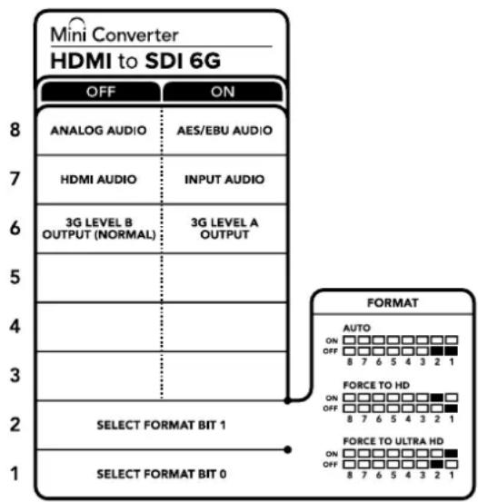
The switch legend on the base of your converter gives you all the information you need to change conversion settings
Blackmagic Converters Setup Settings
The Converters Setup utility can be used to change settings and update your Mini Converter's software. You can access these settings by moving between the 'audio,' and 'about' tabs. The 'about' tab is detailed in the 'changing settings' section in this manual. The 'audio' tab for Mini Converter HDMI to SDI 6G contains the following settings.
Input Levels menu
This menu allows you to adjust the gain on the audio input. You can adjust audio levels independently per channel, or together by clicking the 'link' icon next to their sliders. To reset all audio levels back to 0 dB click the 'reset' button at the top of the 'input levels' menu.
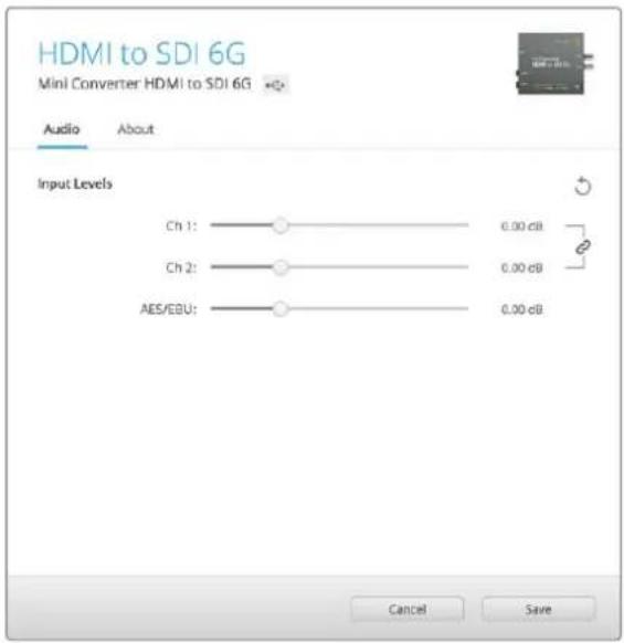
Use the 'audio' tab in Converters Setup to adjust audio levels.
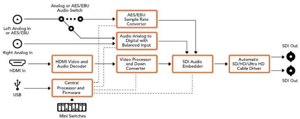
Mini Converter HDMI to SDI 6G Block Diagram
flowchart
graph TD
    A["Left Analog In or AES/EBU"] --> B["Analog or AES/EBU Audio Switch"]
    C["Right Analog In"] --> D["HDMI In"]
    E["USB"] --> F["Central Processor and Firmware"]
    B --> G["AES/EBU Sample Rate Converter"]
    D --> H["HDMI Video and Audio Decoder"]
    F --> I["Video Processor and Down Converter"]
    G --> J["SDI Audio Embedder"]
    H --> J
    I --> J
    J --> K["Automatic SD/HD/Ultra HD Cable Driver"]
    K --> L["SDI Out"]
    G --> M["Audio Analog to Digital with Balanced Input"]
    H --> N["Video Processor and Down Converter"]
    I --> O["SDI Audio Embedder"]
    N --> P["SDI Out"]
    style A fill:#f9f,stroke:#333
    style C fill:#f9f,stroke:#333
    style E fill:#f9f,stroke:#333
    style B fill:#ccf,stroke:#333
    style D fill:#ccf,stroke:#333
    style F fill:#ccf,stroke:#333
    style G fill:#cfc,stroke:#333
    style H fill:#cfc,stroke:#333
    style I fill:#cfc,stroke:#333
    style J fill:#ffc,stroke:#333
    style K fill:#ffc,stroke:#333
    style L fill:#cfc,stroke:#333
    style M fill:#fcc,stroke:#333
    style N fill:#fcc,stroke:#333
    style O fill:#fcc,stroke:#333
Mini Converter SDI to Analog
Your Blackmagic Mini Converter SDI to Analog converts from SD/HD-SDI to analog component, NTSC and PAL video out, plus balanced AES/EBU and analog audio out. Your converter easily connects to analog video monitors and decks such as Betacam SP and VHS. A hardware down converter lets you connect HD-SDI video to SD analog equipment. You can even output pairs of analog audio from 16 de-embedded SDI audio channels.
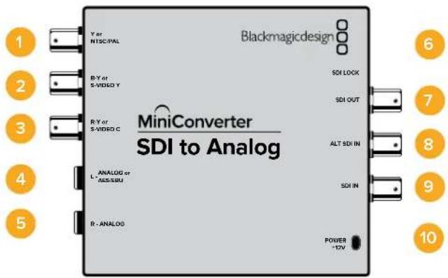
Connectors
1 Y or NTSC/PAL
Analog component Y, or composite NTSC/PAL output on a BNC connector.
2 B-Y or S-VIDEO Y
Analog component B-Y, or S-Video Y output BNC connector.
3 R-Y or S-VIDEO C
Analog component R-Y, or S-Video C output BNC connector.
4 L - ANALOG or AES/EBU
Balanced left channel analog audio, or AES/EBU digital audio output on a 1/4" jack connector.
5 R - ANALOG
Balanced right channel analog audio output 1/4" jack connector.
6 MINI-B USB PORT
Connects to the Converters Setup software via your Mac OS X or Windows computer. The Mini Converter's internal software is also updated using the USB port.
7 SDI OUT
SDI video output on a BNC connector.
8 ALT SDI IN
Redundant SDI input is provided as an optional back up.
9 SDI IN
Primary SDI input.
10 POWER +12V
12 volt power supply input.
Switches
Switch 8 - Analog Audio, AES/EBU Audio
Set switch 8 to OFF to select balanced analog audio, or to ON for digital AES/EBU audio output.
Switch 7 - 7.5 IRE - 0.0 IRE
The USA and countries using NTSC with 7.5 setup should set switch 7 to OFF. If you're working in countries not using 7.5 setup, set switch 7 to ON. This setting only affects composite or S-Video outputs.
Switch 6 - SMPTE Levels - Betacam Levels
Set switch 6 to OFF for SMPTE levels, or ON for Betacam levels. SMPTE levels are more common and even Betacam SP decks can use SMPTE levels, so only switch this to Betacam if you are sure that Betacam levels are being used.
Switch 5 - Component, Composite or S-Video
Set switch 5 to OFF to select analog component video output, or ON for composite and S-Video outputs.
To display the HD video input on the S-Video and composite outputs, down conversion must be set to ON. Component analog video supports both HD and SD video.
Switch 4 - SDI Audio De-Embed B it 2
Switches 4, 3 and 2 are grouped together to provide 8 ON/OFF combinations. Having eight different combinations allows eight independent pairs of audio channels to be de-embedded from your SDI input.
Switch 3 - SDI Audio De-Embed Bit 1
See switch 4 description.
Switch 2 - SDI Audio De-Embed Bit 0
See switch 4 description.
Switch 1 - Processing Off - Processing On
Down convert HD to SD with 3 types of aspect ratios by cycling through switch 1. For example, each time you cycle between Off and On you apply anamorphic, center cut or letterbox aspect ratios. Leaving switch 1 set to OFF bypasses the down converter and outputs in HD.
When connected to Blackmagic Converters Setup via USB, your down conversion settings are controlled by the software. If you want the converter to remember your software settings, disconnect from the computer, power cycle your converter and set your down conversion using switch 1.
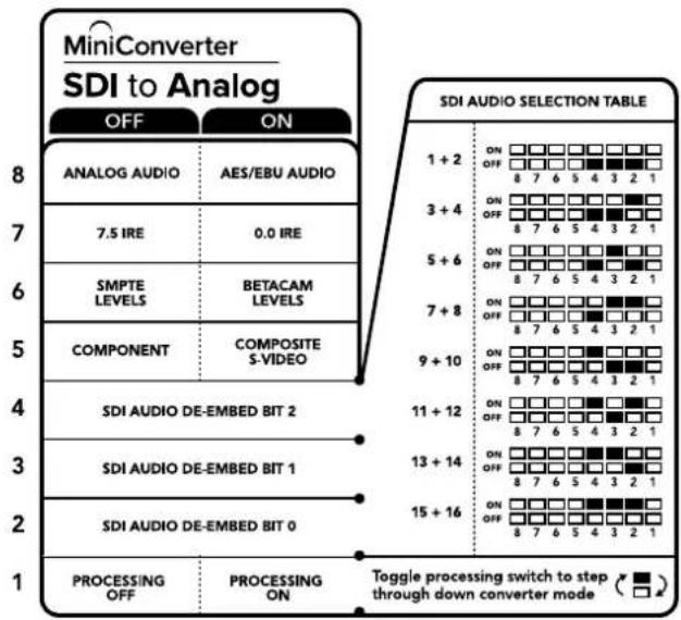
The switch legend on the base of your converter gives you all the information you need to change conversion settings.
Mini Switch Settings Example
Experiment with the switches by setting your Blackmagic Mini Converter to output high definition component video and analog audio channels 1 and 2 by setting switches 8, 5, 4, 3 and 2 to the OFF position.
SDI Audio Selection Table
| Audio Channels Switch 4 Switch 3 Switch 2 Switch Diagram | |||
| 1 and 2 OFF OFF OFF | 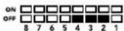 | ||
| 3 and 4 OFF OFF ON | 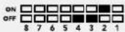 | ||
| 5 and 6 OFF ON OFF | 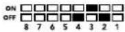 | ||
| 7 and 8 OFF ON ON | 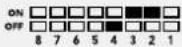 | ||
| 9 and 10 ON OFF OFF | 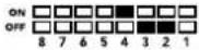 | ||
| 11 and 12 ON OFF ON | 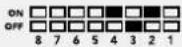 | ||
| 13 and 14 ON ON OFF | 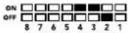 | ||
| 15 and 16 ON ON ON | 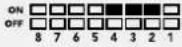 | ||
Blackmagic Converters Setup Settings
The Converters Setup utility can be used to change settings and update your Mini Converter's software. You can access these settings by moving between the 'video,' 'audio,' and 'about' tabs.
The ‘about’ tab is detailed in the ‘changing settings’ section in this manual.
The 'video' tab for Mini Converter SDI to Analog contains the following settings.
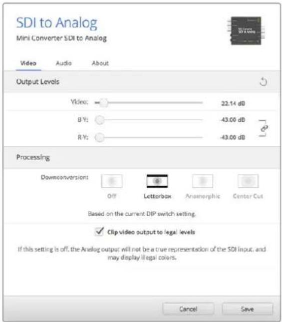
Use the 'video' tab in Converters Setup to adjust analog video levels and processing settings.
Processing menu
This menu allows you to set the aspect ratio of down converted video. The options are letterbox, anamorphic, center cut or no processing.
The ‘clip video output to legal levels’ checkbox controls clipping of your SDI input to ensure that it stays within HDMI legal levels and should be kept on by default.
Output Levels menu
This lets you set the luminance and chroma levels, and the B-Y and R-Y component levels independently.
The 'audio' tab for Mini Converter SDI to Analog contains the following settings.
Output Levels menu
This menu allows you to adjust the gain on the audio output. You can adjust audio levels independently per channel, or together by clicking the 'link' icon next to their sliders. To reset all audio levels back to 0 dB click the 'reset' button at the top of the 'output levels' menu.
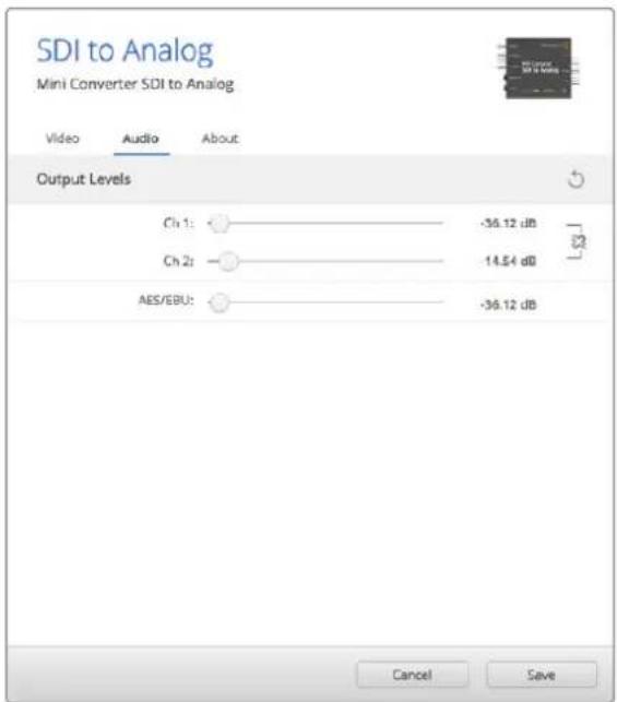
Use the 'audio' tab in Converters Setup to adjust analog audio levels.
Mini Converter SDI to Analog Block Diagram
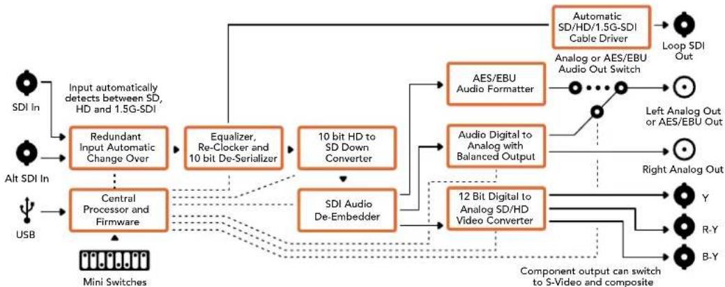
flowchart
graph TD
    A["SDI In"] --> B["Input automatically detects between SD, HD and 1.5G-SDI"]
    C["Alt SDI In"] --> D["Central Processor and Firmware"]
    E["USB"] --> D
    B --> F["Redundant Input Automatic Change Over"]
    D --> G["SDI Audio De-Embedder"]
    F --> H["Equalizer, Re-Clocker and 10 bit De-Serializer"]
    G --> I["10 bit HD to SD Down Converter"]
    H --> J["AES/EBU Audio Formatter"]
    I --> K["Audio Digital to Analog with Balanced Output"]
    J --> L["Automatic SD/HD/1.5G-SDI Cable Driver"]
    K --> M["12 Bit Digital to Analog SD/HD Video Converter"]
    L --> N["Loop SDI Out"]
    M --> O["Component output can switch to S-Video and composite"]
    N --> P["Y"]
    N --> Q["R-Y"]
    N --> R["B-Y"]
    style A fill:#f9f,stroke:#333
    style C fill:#f9f,stroke:#333
    style E fill:#f9f,stroke:#333
    style B fill:#ccf,stroke:#333
    style D fill:#ccf,stroke:#333
    style F fill:#cfc,stroke:#333
    style G fill:#cfc,stroke:#333
    style H fill:#fcc,stroke:#333
    style I fill:#fcc,stroke:#333
    style J fill:#cff,stroke:#333
    style K fill:#cff,stroke:#333
    style L fill:#ffc,stroke:#333
    style M fill:#ffc,stroke:#333
    style N fill:#ffc,stroke:#333
    style O fill:#ffc,stroke:#333
    style P fill:#ffc,stroke:#333
    style Q fill:#ffc,stroke:#333
    style R fill:#ffc,stroke:#333
    style S fill:#ffc,stroke:#333
    style T fill:#ffc,stroke:#333
    style U fill:#ffc,stroke:#333
Mini Converter SDI to Analog 4K
Your Mini Converter SDI to Analog 4K and the SDI to Analog 4K Heavy Duty model can convert from SD/HD/3G/6G-SDI to analog component, NTSC and PAL video out, plus balanced AES/EBU and analog audio out. This down converter lets you connect up to 6G-SDI video to SD or HD analog equipment and easily connects to video monitors and decks such as Betacam SP and VHS. You can even output pairs of analog audio from 16 de-embedded SDI audio channels.
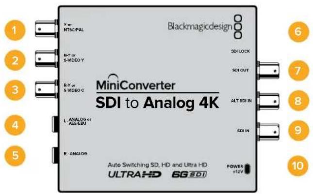
Connectors
1 Y or NTSC/PAL
Analog component Y or composite NTSC/PAL output BNC connector.
2 B-Y or S-VIDEO Y
Analog component B-Y, or S-Video Y output BNC connector.
3 R-Y or S-VIDEO C
Analog component R-Y, or S-Video C output BNC connector.
4 L - ANALOG or AES/EBU
Balanced left channel analog audio, or AES/EBU digital audio output 1/4" jack connector.
5 R - ANALOG
Balanced right channel analog audio output 1/4" jack connector.
6 MINI-B USB PORT
Connects to the Converters Setup software via your Mac OS X or Windows computer. The Mini Converter's internal software is also updated using the USB port.
7 SDI OUT
SDI video output BNC connector.
8 ALT SDI IN
Redundant SDI input is provided as an optional back up.
9 SDI IN
Primary SDI input.
10 POWER +12V
12 volt power supply input.
Switches
TIP On the Mini Converter Heavy Duty model, the switches are protected by a rubber dust cover. Simply lift the edge of the cover to access the switches.
Mini Converter SDI to Analog 4K's switches provide the following settings:
Switch 8 - Analog Audio, AES/EBU Audio
Set switch 8 to OFF to select balanced analog audio, or to ON for digital AES/EBU audio output.
Switch 7 - 7.5 IRE - 0.0 IRE
The USA and countries using NTSC with 7.5 setup should set switch 7 to OFF. If you're working in countries not using 7.5 setup, set switch 7 to ON. This setting only affects composite or S-Video outputs.
Switch 6 - SMPTE Levels - Betacam Levels
Set switch 6 to OFF for SMPTE levels, or ON for Betacam levels. SMPTE levels are more common and even Betacam SP decks can use SMPTE levels, so only switch this to Betacam if you are sure that Betacam levels are being used.
Switch 5 - Component, Composite or S-Video
Set switch 5 to OFF to select analog component video output, or ON for composite and S-Video outputs.
To display the HD video input as SD on the S-Video and composite outputs, down conversion must be set to ON. Component analog video supports both HD and SD video.
Switch 4, 3 and 2 - SDI Audio De-Embed
Switches 4, 3 and 2 are grouped together to provide 8 ON/OFF combinations. Having eight different combinations allows eight independent pairs of audio channels to be de-embedded from your SDI input.
Switch 1 - Processing Off - Processing On
Down conversion with 3 types of aspect ratios by cycling through switch 1. Each time you cycle between Off and On you apply anamorphic, center cut or letterbox aspect ratios.
For both HD and Ultra HD input, set switch to OFF to output HD analog via the component outputs.
Set switch to ON and Ultra HD input downconverts to either analog PAL/NTSC or HD component depending on the other switch settings. 4K DCI will be cropped on the component HD output.
An ON setting with HD input will be downconverted to analog PAL/NTSC or component depending on the other switch settings.
When connected to Blackmagic Converters Setup via USB, your down conversion settings are controlled by the software. If you want the converter to remember your software settings, disconnect from the computer, power cycle your converter and set your down conversion using switch 1.
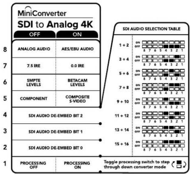
The switch legend on the base of your converter gives you all the information you need to change conversion settings.
Mini Switch Settings Example:
Experiment with the switches by setting your Blackmagic Mini Converter to output high definition component video and analog audio channels 1 and 2 by setting switches 8, 5, 4, 3 and 2 to the OFF position.
Audio Selection Table
| Audio Channels Switch 4 Switch 3 Switch 2 Switch Diagram | |||
| 1 and 2 OFF OFF OFF | 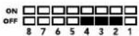 | ||
| 3 and 4 OFF OFF ON | 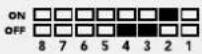 | ||
| 5 and 6 OFF ON OFF | 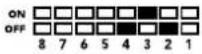 | ||
| 7 and 8 OFF ON ON | 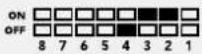 | ||
| 9 and 10 ON OFF OFF | 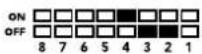 | ||
| 11 and 12 ON OFF ON | 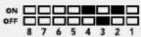 | ||
| 13 and 14 ON ON OFF | 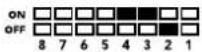 | ||
| 15 and 16 ON ON ON | 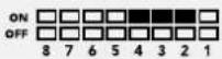 | ||
Blackmagic Converters Setup Settings
The Converters Setup utility can be used to change settings and update your Mini Converter's software. You can access these settings by moving between the 'video,' 'audio,' and 'about' tabs.
The ‘about’ tab is detailed in the ‘changing settings’ section in this manual.
The 'video' tab for Mini Converter SDI to Analog 4K contains the following settings.
Output Levels menu
This lets you set the luminance and chroma levels, and the B-Y and R-Y component levels independently.
Processing menu
This menu allows you to set the aspect ratio of down converted video. The options are letterbox, anamorphic, center cut or no processing.
The ‘clip video output to legal levels’ checkbox controls clipping of your SDI input to ensure that it stays within HDMI egal levels and should be kept on by default.
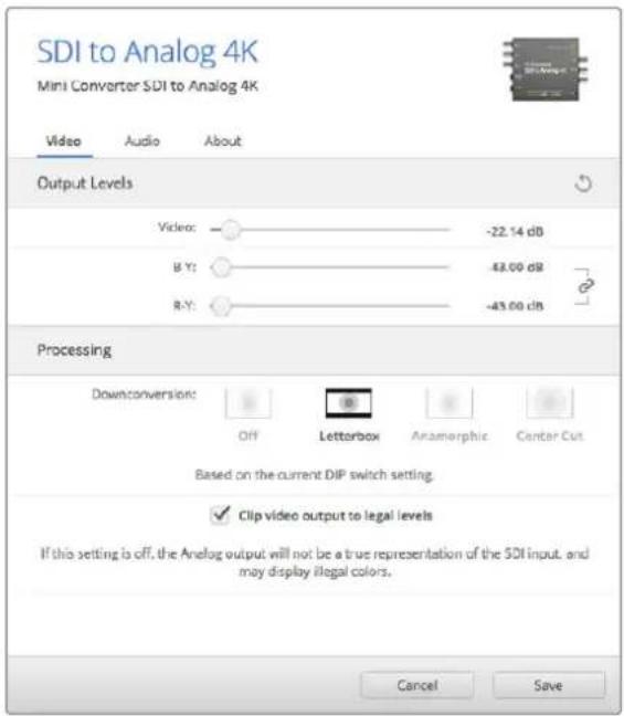
Use the 'video' tab in Converters Setup to adjust analog video levels and processing settings.
The 'audio' tab for Mini Converter SDI to Analog 4K contains the following settings.
Output Levels menu
This menu allows you to adjust the gain on the audio input. You can adjust audio levels independently per channel, or together by clicking the 'link' icon next to their sliders. To reset all audio levels back to 0 dB click the 'reset' button at the top of the 'output levels' menu.
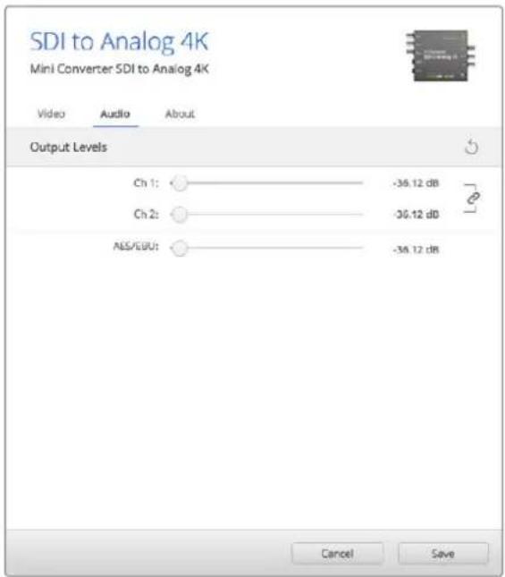
Use the 'audio' tab in Converters Setup to adjust analog audio levels.
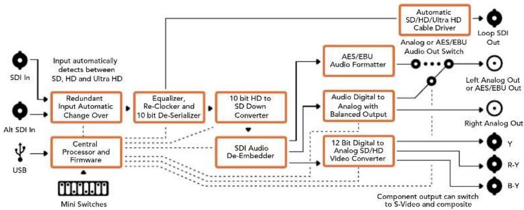
Mini Converter SDI to Analog 4K Block Diagram
flowchart
graph TD
    A["SDI In"] --> B["Input automatically detects between SD, HD and Ultra HD"]
    C["Alt SDI In"] --> D["Central Processor and Firmware"]
    E["USB"] --> D
    B --> F["Redundant Input Automatic Change Over"]
    D --> G["Equalizer, Re-Clocker and 10 bit De-Serializer"]
    G --> H["10 bit HD to SD Down Converter"]
    H --> I["SDI Audio De-Embedder"]
    I --> J["AES/EBU Audio Formatter"]
    I --> K["Audio Digital to Analog with Balanced Output"]
    J --> L["Automatic SD/HD/Ultra HD Cable Driver"]
    K --> M["12 Bit Digital to Analog SD/HD Video Converter"]
    L --> N["Loop SDI Out"]
    M --> O["Analog or AES/EBU Audio Out Switch"]
    N --> P["Left Analog Out or AES/EBU Out"]
    O --> Q["Right Analog Out"]
    P --> R["Y"]
    P --> S["R-Y"]
    P --> T["B-Y"]
    U["Component output can switch to S-Video and composite"] --> V["Output"]
    W["Mini Switches"] --> X["Data Inputs"]
Mini Converter Analog to SDI
With your Mini Converter Analog to SDI and the Analog to SDI Heavy Duty model you can convert video and audio from analog equipment such as Betacam SP decks, HDV cameras and game consoles to SD/HD-SDI video. A choice of analog and digital formats is supported, including component SD/HD, S-Video, or composite NTSC and PAL. The converter's HD-SDI outputs include the option to embed digital AES/EBU or analog audio.
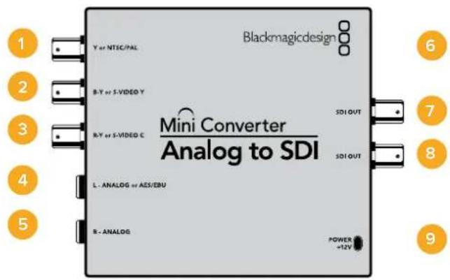
Connectors
1 Y or NTSC/PAL
Analog component Y, or composite NTSC/PAL input BNC connector.
2 B-Y or S-VIDEO Y
Analog component B-Y, or S-Video Y input BNC connector.
3 R-Y or S-VIDEO C
Analog component R-Y, or S-Video C input BNC connector.
4 L - ANALOG or AES/EBU
Balanced left channel analog audio, or AES/EBU digital audio input 1/4" jack connector.
5 R - ANALOG
Balanced right channel analog audio input 1/4" jack connector.
6 MINI-B USB PORT
Connects to the Converters Setup software via your Mac OS X or Windows computer.
The Mini Converter's internal software is also updated using the USB port.
7 SDI OUT
SDI video output BNC connector.
8 SDI OUT
Second SDI output.
9 POWER +12V
12 volt power supply input.
Switches
TIP On the Mini Converter Heavy Duty model, the switches are protected by a rubber dust cover. Simply lift the edge of the cover to access the switches.
Mini Converter Analog to SDI's switches provide the following settings:
Switch 8 - Analog Audio, AES/EBU Audio
Set switch 8 to OFF to select balanced analog audio, or to ON for digital AES/EBU audio input.
Switch 7 - 7.5 IRE - 0.0 IRE
The USA and countries using NTSC with 7.5 setup should set switch 7 to OFF. If you're working in countries not using 7.5 setup, for example Japan, set switch 7 to ON. This setting only affects composite or S-Video outputs.
Switch 6 - SMPTE Levels - Betacam Levels
This setting selects between SMPTE or Betacam video levels. Set switch 6 to OFF for SMPTE levels, or to ON for Betacam levels. SMPTE levels are more common and even Betacam SP decks can use SMPTE levels so only switch this to Betacam if you are sure that Betacam levels are being used.
Switch 5 - Component, Composite or S-Video
Set switch 5 to OFF to select analog component video input, or to ON for composite video and S-Video analog inputs.
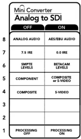
The switch legend on the base of your converter gives you all the information you need to change conversion settings.
Switch 4 - Composite - S-Video
Set switch 4 to OFF to select composite video input, or to ON for S-Video input.
Switch 1 - Processing Off - Processing On
This switch is not used.
Mini Switch Settings Example
Experiment with the switches by setting your Blackmagic Mini Converter to Component and Analog Audio input by setting switches 8 and 5 to the OFF position.
Blackmagic Converters Setup Settings
The Converters Setup utility can be used to change settings and update your Mini Converter's software. You can access these settings by moving between the 'video,' 'audio,' and 'about' tabs.
The ‘about’ tab is detailed in the ‘changing settings’ section in this manual.
The 'video' tab for Mini Converter Analog to SDI contains the following settings.
Input Levels menu
This lets you set the luminance and chroma levels, and the B-Y and R-Y component levels independently.
The ‘audio’ tab for Mini Converter Analog to SDI contains the following settings.
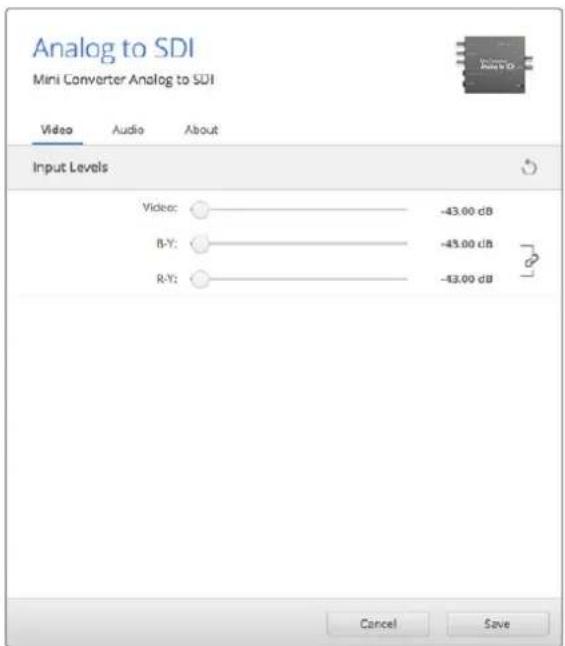
Use the 'video' tab in Converters Setup to adjust video levels.
Input Levels menu
This menu allows you to adjust the gain on the audio input. You can adjust audio levels independently per channel, or together by clicking the 'link' icon next to their sliders. To reset all audio levels back to 0 dB click the 'reset' button at the top of the 'input levels' menu.
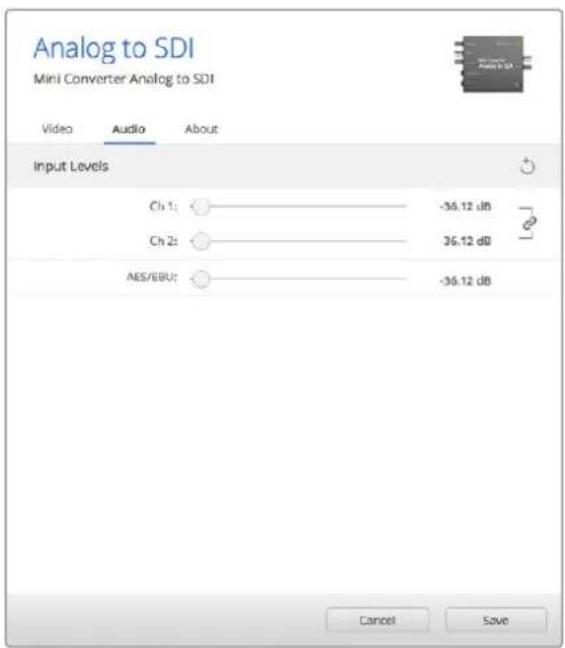
Use the 'audio' tab in Converters Setup to adjust analog audio levels.
Mini Converter Analog to SDI Block Diagram
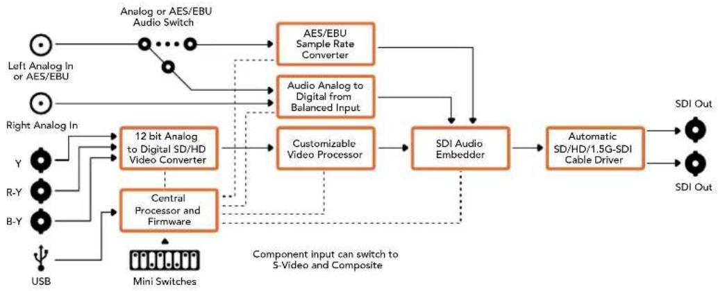
flowchart
graph TD
    A["Left Analog In or AES/EBU"] --> B["Analog or AES/EBU Audio Switch"]
    C["Right Analog In"] --> D["12 bit Analog to Digital SD/HD Video Converter"]
    E["Y"] --> D
    F["R-Y"] --> D
    G["B-Y"] --> H["Central Processor and Firmware"]
    I["USB"] --> H
    B --> J["AES/EBU Sample Rate Converter"]
    B --> K["Audio Analog to Digital from Balanced Input"]
    J --> L["Customizable Video Processor"]
    K --> L
    L --> M["SDI Audio Embedder"]
    M --> N["Automatic SD/HD/1.5G-SDI Cable Driver"]
    N --> O["SDI Out"]
    P["Mini Switches"] --> H
    Q["Component input can switch to 5-Video and Composite"] -.-> L
Mini Converter SDI to Audio
Your Mini Converter SDI to Audio can de-embed 4 channels of audio from any SDI video connection and output to 4 channels of analog audio or 8 channels of AES/EBU digital. Output to audio equipment such as audio mixers, analog decks and reference monitors. Additional SDI audio channels can be de-embedded by daisy chaining another Mini Converter SDI to Audio to your converter's SDI output.
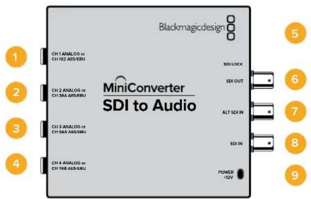
Connectors
1 CH 1 ANALOG or CH 1 & 2 AES/EBU
Balanced analog audio channel 1, or AES/EBU digital audio channels 1 and 2 output 1/4" jack connector.
2 CH 2 Analog or CH 3 & 4 AES/EBU
Balanced analog audio channel 2, or AES/EBU digital audio channels 3 and 4 output 1/4" jack connector.
3 CH 3 Analog or CH 5 & 6 AES/EBU
Balanced analog audio channel 3, or AES/EBU digital audio channels 5 and 6 output 1/4" jack connector.
4 CH 4 Analog or CH 7 & 8 AES/EBU
Balanced analog audio channel 4, or AES/EBU digital audio channels 7 and 8 output 1/4" jack connector.
5 MINI-B USB PORT
Connects to the Converters Setup software via your Mac OS X or Windows computer. The Mini Converter's internal software is also updated using the USB port.
6 SDI OUT
Loop through SDI video output BNC connector.
7 ALT SDI IN
Redundant SDI input provided as an optional back up. When using both the SDI IN and ALT SDI IN, the ALT SDI IN will take over should the SDI IN signal fail. The SDI LOCK LED will flash indicating that the converter has switched to the ALT SDI IN.
8 SDI IN
Primary SDI input.
9 POWER +12V
12 volt power supply input.
Switches
Mini Converter SDI to Audio's switches provide the following settings:
Switch 8 - Analog Audio, AES/EBU Audio
Set switch 8 to OFF to select balanced analog audio, or to ON for digital AES/EBU audio output.
Switch 6 - Audio Group Bit 1
Switches 6 and 5 are grouped together to provide four ON/OFF combinations. This allows up to 4 quadruplets of analog audio channels, or 2 sets of 8 AES/EBU audio channels, to be de-embedded from your SDI input.
Switch 5 - Audio Group Bit 0
See switch 6 description.
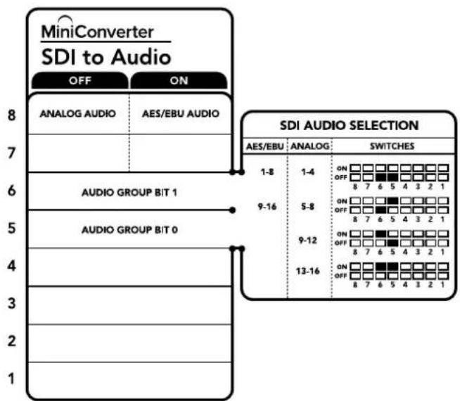
flowchart
graph TD
    A["MINIConverter SDI to Audio"] --> B["OFF"]
    A --> C["ON"]
    D["ANALOG AUDIO"] --> E["AES/EBU AUDIO"]
    F["SDI AUDIO SELECTION"] --> G["AES/EBU: ANALOG: SWITCHES"]
    H["AUDIO GROUP BIT 1"] --> I["9-16"]
    J["AUDIO GROUP BIT 0"] --> K["9-12"]
    L["13-16"] --> M["8 7 6 5 4 3 2 1"]
The switch legend on the base of your converter gives you all the information you need to change conversion settings.
Mini Switch Settings Example
Try experimenting with the switches. Select analog audio channels 1 to 4 by setting switches 8, 6 and 5 to the OFF position.
Audio Selection Tables
| Analog Audio Channels Switch 6 Switch 5 Switch Diagram | |||
| 1 to 4 OFF OFF | 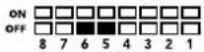 | ||
| 5 to 8 OFF ON | 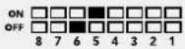 | ||
| 9 to 12 ON OFF | 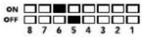 | ||
| 13 to 16 ON ON | 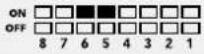 | ||
| AES/EBU Channels Switch 6 Switch 5 Switch Diagram | |||
| 1 to 8 OFF OFF | ONOFF8 7 6 5 4 3 2 1 | ||
| 9 to 16 OFF ON | ONOFF8 7 6 5 4 3 2 1 | ||
Blackmagic Converters Setup Settings
The Converters Setup utility can be used to change settings and update your Mini Converter's software. You can access these settings by moving between the 'audio,' and 'about' tabs.
The ‘about’ tab is detailed in the ‘changing settings’ section in this manual.
The 'audio' tab for Mini Converter SDI to Audio contains the following settings.
Output Levels menu
This menu allows you to adjust the gain on the audio output. You can adjust audio levels independently per channel, or together as channel pairs by clicking the 'link' icon next to their sliders. To reset all audio levels back to 0 dB click the 'reset' button at the top of the 'output levels' menu.
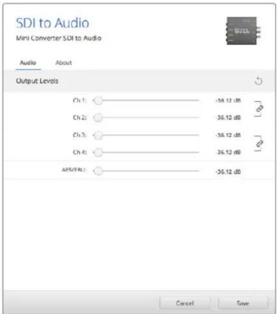
Use the 'audio' tab in Converters Setup to adjust audio levels.
Mini Converter SDI to Audio Block Diagram
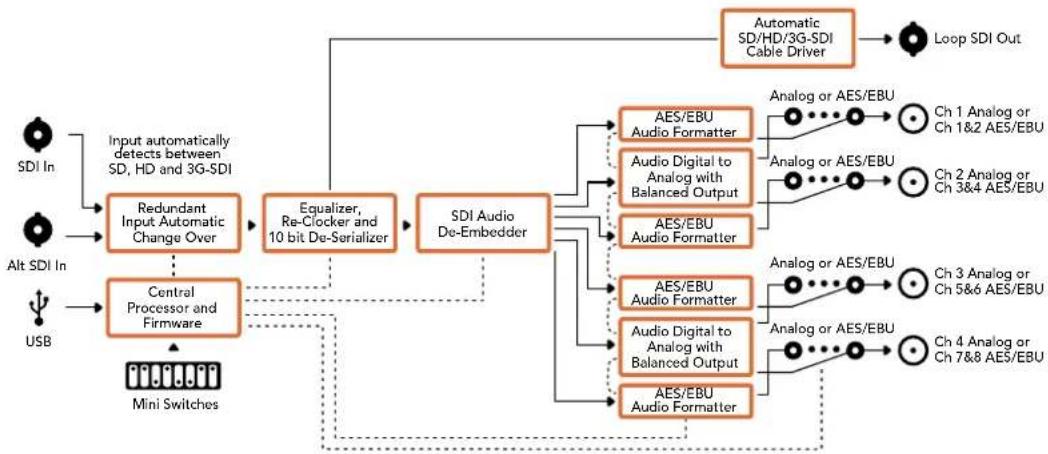
flowchart
graph TD
    A["SDI In"] --> B["Input automatically detects between SD, HD and 3G-SDI"]
    C["Alt SDI In"] --> D["Central Processor and Firmware"]
    E["USB"] --> D
    B --> F["Redundant Input Automatic Change Over"]
    D --> F
    F --> G["Equalizer, Re-Clocker and 10 bit De-Serializer"]
    G --> H["SDI Audio De-Embedder"]
    H --> I["AES/EBU Audio Formatter"]
    H --> J["Audio Digital to Analog with Balanced Output"]
    H --> K["AES/EBU Audio Formatter"]
    I --> L["Automatic SD/HD/3G-SDI Cable Driver"]
    J --> L
    K --> L
    L --> M["Loop SDI Out"]
    I --> N["Ch 1 Analog or Ch 1&2 AES/EBU"]
    J --> O["Ch 2 Analog or Ch 3&4 AES/EBU"]
    K --> P["Ch 3 Analog or Ch 5&6 AES/EBU"]
    L --> Q["Ch 4 Analog or Ch 7&8 AES/EBU"]
    M --> R["Output"]
    N --> R
    O --> R
    P --> R
    Q --> R
Mini Converter SDI to Audio 4K
With Mini Converter SDI to Audio 4K you can de-embed 4 channels of audio from any SDI video connection and output to 4 channels of analog audio or 8 channels of AES/EBU digital. Output to audio equipment such as audio mixers, analog decks and reference monitors. Additional SDI audio channels can be de-embedded by daisy chaining another Mini Converter SDI to Audio 4K to your converter's SDI output.
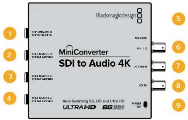
Connectors
1 CH 1 ANALOG or CH 1 & 2 AES/EBU
Balanced analog audio channel 1, or AES/EBU digital audio channels 1 and 2 output 1/4" jack connector.
2 CH 2 Analog or CH 3 & 4 AES/EBU
Balanced analog audio channel 2, or AES/EBU digital audio channels 3 and 4 output 1/4" jack connector.
3 CH 3 Analog or CH 5 & 6 AES/EBU
Balanced analog audio channel 3, or AES/EBU digital audio channels 5 and 6 output 1/4" jack connector.
4 CH 4 Analog or CH 7 & 8 AES/EBU
Balanced analog audio channel 4, or AES/EBU digital audio channels 7 and 8 output 1/4" jack connector.
5 MINI-B USB PORT
Connects to the Converters Setup software via your Mac OS X or Windows computer. The Mini Converter's internal software is also updated using the USB port.
6 SDI OUT
Loop through SDI video output BNC connector.
7 ALT SDI IN
Redundant SDI input provided as an optional back up. When using both the SDI IN and ALT SDI IN, the ALT SDI IN will take over should the SDI IN signal fail. The SDI LOCK LED will flash indicating that the converter has switched to the ALT SDI IN.
8 SDI IN
Primary SDI input.
9 POWER +12V
12 volt power supply input.
Switches
Mini Converter SDI to Audio 4K switches provide the following settings:
Switch 8 - Analog Audio, AES/EBU Audio
Set switch 8 to OFF to select balanced analog audio, or to ON for digital AES/EBU audio output.
Switch 6 - Audio Group Bit 1
Switches 6 and 5 are grouped together to provide four ON/OFF combinations. This allows up to 4 quadruplets of analog audio channels, or 2 sets of 8 AES/EBU audio channels, to be de-embedded from your SDI input.
Switch 5 - Audio Group Bit 0
See switch 6 description.
Mini Switch Settings Example
Try experimenting with the switches. Select analog audio channels 1 to 4 by setting switches 8, 6 and 5 to the OFF position.
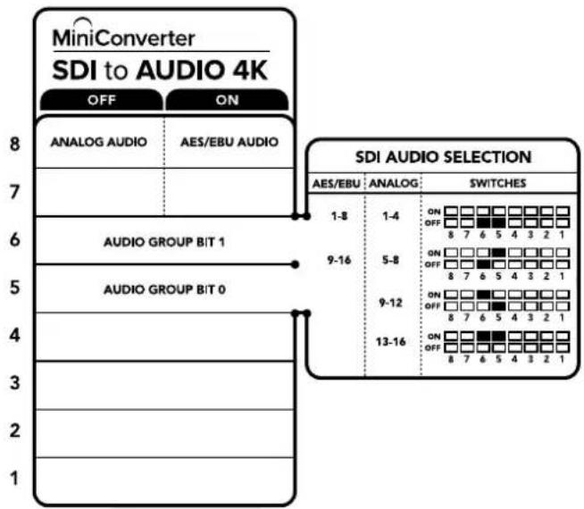
flowchart
graph TD
    A["MINIConverter SDI to AUDIO 4K"] --> B["OFF ON"]
    B --> C["ANALOG AUDIO"]
    B --> D["AES/EBU AUDIO"]
    C --> E["6 AUDIO GROUP BIT 1"]
    D --> F["6 AUDIO GROUP BIT 0"]
    E --> G["9-16"]
    F --> H["9-12"]
    G --> I["13-16"]
    H --> J["13-16"]
    I --> K["13-16"]
The switch legend on the base of your converter gives you all the information you need to change conversion settings.
Audio Selection Tables
| Analog Audio Channels Switch 6 Switch 5 Switch Diagram | |||
| 1 to 4 OFF OFF | 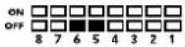 | ||
| 5 to 8 OFF ON | 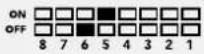 | ||
| 9 to 12 ON OFF | 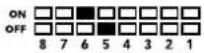 | ||
| 13 to 16 ON ON | 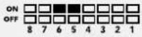 | ||
| AES/EBU Channels Switch 6 Switch 5 Switch Diagram | |||
| 1 to 8 OFF OFF | ONOFF8 7 6 5 4 3 2 1 | ||
| 9 to 16 OFF ON | ONOFF8 7 6 5 4 3 2 1 | ||
Blackmagic Converters Setup Settings
The Converters Setup utility can be used to change settings and update your Mini Converter's software. You can access these settings by moving between the 'audio,' and 'about' tabs.
The ‘about’ tab is detailed in the ‘changing settings’ section in this manual.
The ‘audio’ tab for Mini Converter SDI to Audio 4K contains the following settings.
Output Levels menu
This menu allows you to adjust the gain on the audio output. You can adjust audio levels independently per channel, or together as channel pairs by clicking the 'link' icon next to their sliders. To reset all audio levels back to 0 dB click the 'reset' button at the top of the 'output levels' menu.
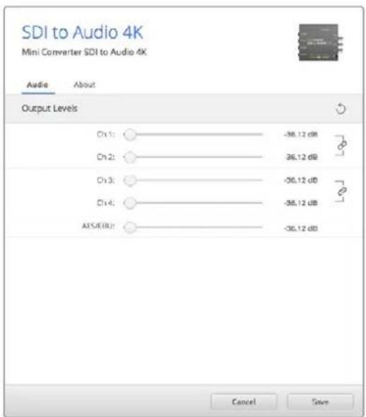
Use the 'audio' tab in Converters Setup to adjust analog audio levels.
Mini Converter SDI to Audio 4K Block Diagram
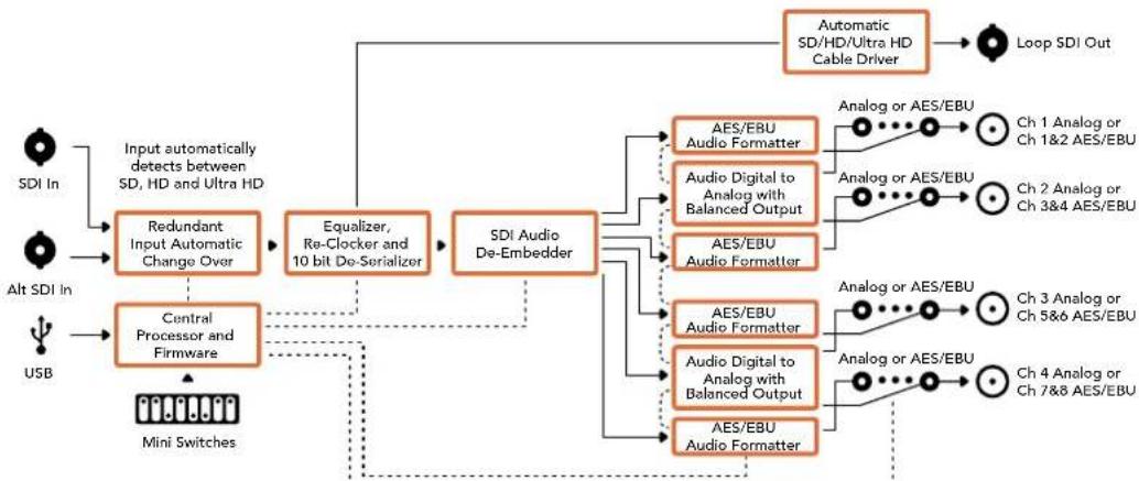
flowchart
graph TD
    A["SDI In"] --> B["Input automatically detects between SD, HD and Ultra HD"]
    C["Alt SDI In"] --> D["Central Processor and Firmware"]
    E["USB"] --> D
    B --> F["Redundant Input Automatic Change Over"]
    D --> G["Equalizer, Re-Clocker and 10 bit De-Serializer"]
    F --> H["SDI Audio De-Embedder"]
    G --> H
    H --> I["AES/EBU Audio Formatter"]
    H --> J["Audio Digital to Analog with Balanced Output"]
    H --> K["AES/EBU Audio Formatter"]
    I --> L["Analog or AES/EBU"]
    J --> M["Analog or AES/EBU"]
    K --> N["Analog or AES/EBU"]
    L --> O["Ch 1 Analog or Ch 1&2 AES/EBU"]
    M --> P["Ch 2 Analog or Ch 3&4 AES/EBU"]
    N --> Q["Ch 3 Analog or Ch 5&6 AES/EBU"]
    O --> R["Ch 4 Analog or Ch 7&8 AES/EBU"]
    P --> S["Ch 4 Analog or Ch 7&8 AES/EBU"]
    T["Mini Switches"] --> D
    U["Automatic SD/HD/Ultra HD Cable Driver"] --> V["Loop SDI Out"]
Mini Converter Audio to SDI
Your Mini Converter Audio to SDI can embed four channels of analog audio, or eight channels of AES/EBU digital audio into any SDI video connection. You can use this Mini Converter to embed audio from equipment, such as audio mixers and analog decks, into SDI video connections for use with SDI routers and decks. Additional SDI audio channels can be embedded by daisy chaining another Mini Converter Audio to SDI to your converter's SDI output.
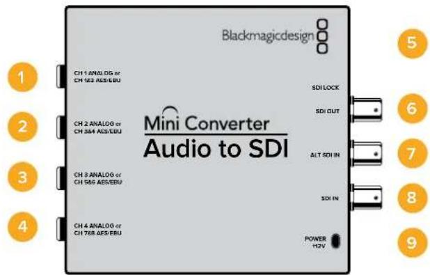
Connectors
1 CH 1 Analog or CH 1 & 2 AES/EBU
Balanced analog audio channel 1, or AES/EBU digital audio channels 1 and 2 input 1/4" jack connector.
2 CH 2 Analog or CH 3 & 4 AES/EBU
Balanced analog audio channel 2, or AES/EBU digital audio channels 3 and 4 input 1/4" jack connector.
3 CH 3 Analog or CH 5 & 6 AES/EBU
Balanced analog audio channel 3, or AES/EBU digital audio channels 5 and 6 input 1/4" jack connector.
4 CH 4 Analog or CH 7 & 8 AES/EBU
Balanced analog audio channel 4, or AES/EBU digital audio channels 7 and 8 input 1/4" jack connector.
5 Mini-B USB PORT
Connects to the Converters Setup software via your Mac OS X or Windows computer. The Mini Converter's internal software is also updated using the USB port.
6 SDI OUT
Loop through SDI video output BNC connector.
7 ALT SDI IN
Redundant SDI input provided as an optional back up. When using both the SDI IN and ALT SDI IN, the ALT SDI IN will take over should the SDI IN signal fail. The SDI LOCK LED will flash indicating that the converter has switched to the ALT SDI IN.
8 SDI IN
Primary SDI input.
9 POWER +12V
12 volt power supply input.
Switches
Mini Converter Audio to SDI's switches provide the following settings:
Switch 8 - Analog Audio, AES/EBU Audio
Set switch 8 to OFF to select balanced analog audio, or to ON for digital AES/EBU audio input.
Switch 7 - Sample Rate Conversion, No Sample Rate Conversion
Set switch 7 to OFF to enable sample rate conversion, or ON to disable sample rate conversion. This switch should almost always be set to OFF to ensure audio is embedded at the correct sample rate for television.
When switch 7 is set to OFF this setting converts the sample rate of your analog or AES/EBU audio and embeds audio into the SDI output at a sample rate of 48 kHz. When switch 7 is set to ON, sample rate conversion is disabled and audio is output at the original sample rate of your input audio.
Switch 6 - Audio Group Bit 1
Switches 6 and 5 are grouped together to provide four ON/OFF combinations. Having four different combinations allows up to four analog audio channels, or eight AES/EBU audio channels to be embedded in your SDI output.
Switch 5 - Audio Group Bit 0
See switch 6 description.
Audio Selection Table
| Analog Audio Channels Switch 6 Switch 5 Switch Diagram | |||
| 1 to 4 OFF OFF | ON □□□□□□□□□OFF □□■■□□□□□8 7 6 5 4 3 2 1 | ||
| 5 to 8 OFF ON | ON □□□□□□□□□OFF □□■□□□□□□8 7 6 5 4 3 2 1 | ||
| 9 to 12 ON OFF | ON □□□□□□□□□OFF □□□□□□□□□8 7 6 5 4 3 2 1 | ||
| 13 to 16 ON ON | ON □□□□□□□□□OFF □□□□□□□□□8 7 6 5 4 3 2 1 | ||
| AES/EBU Channels | Switch 6 Switch 5 Switch Diagram | ||
| 1 to 8 OFF OFF | ON □□□□□□□□□OFF □□■□□□□□□8 7 6 5 4 3 2 1 | ||
| 9 to 16 | OFF ON | ON □□□□□□□□□OFF □□□□□□□□□8 7 6 5 4 3 2 1 | |
Embedding or Disabling Channels
Once you have selected your audio channels, use switches 4, 3, 2 and 1 to select which channels to embed or disable. The disable setting lets you avoid overwriting audio channels you wish to keep in the SDI signal.
For example, you can disable analog audio channel 1 or AES/EBU channels 1 and 2 by setting switch 1 to the ON position. Alternatively, you can embed the audio channels by setting switch 1 to the OFF position.
Audio Channel De-Embed or Disable Settings
Switch Setting Audio Channels
| ON Disable analog CH 4, AES/EBU CH 7 and 8 | |
| 4 | OFF Embed analog CH 4, AES/EBU CH 7 and 8 |
| ON Disable analog CH 3, AES/EBU CH 5 and 6 | |
| 3 | OFF Embed analog CH 3, AES/EBU CH 5 and 6 |
| ON Disable analog CH 2, AES/EBU CH 3 and 4 | |
| 2 | OFF Embed analog CH 2, AES/EBU CH 3 and 4 |
| ON Disable analog CH 1, AES/EBU CH 1 and 2 | |
| 1 | OFF Embed analog CH 1, AES/EBU CH 1 and 2 |
The switch legend on the base of your converter gives you all the information you need to change conversion settings.
Mini Switch Settings Example:
Try experimenting with the switches. Select analog audio channels 1 to 4 by setting switches 8, 6 and 5 to the OFF position.
Blackmagic Converters Setup Settings
The Converters Setup utility can be used to change settings and update your Mini Converter's software. You can access these settings by moving between the 'audio,' and 'about' tabs.
The 'about' tab is detailed in the 'changing settings' section in this manual.
The 'audio' tab for Mini Converter Audio to SDI contains the following settings.
Input Levels menu
This menu allows you to adjust the gain on the audio input. You can adjust audio levels independently per channel, or together as channel pairs by clicking the 'link' icon next to their sliders. To reset all audio levels back to 0 dB click the 'reset' button at the top of the 'output levels' menu.
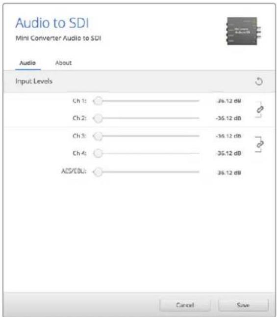
Use the 'audio' tab in Converters Setup to adjust analog audio levels.
Mini Converter Audio to SDI Block Diagram
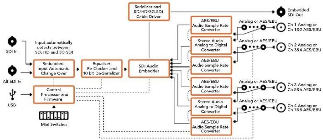
flowchart
graph TD
    A["SDI In"] --> B["Input automatically detects between SD, HD and 3G-SDI"]
    C["Alt SDI In"] --> D["Central Processor and Firmware"]
    E["USB"] --> D
    B --> F["Redundant Input Automatic Change Over"]
    D --> F
    F --> G["Equalizer, Re-Clocker and 10 bit De-Serializer"]
    G --> H["SDI Audio Embedder"]
    H --> I["AES/EBU Audio Sample Rate Converter"]
    H --> J["Stereo Audio Analog to Digital Converter"]
    H --> K["AES/EBU Audio Sample Rate Converter"]
    H --> L["AES/EBU Audio Sample Rate Converter"]
    H --> M["Stereo Audio Analog to Digital Converter"]
    H --> N["AES/EBU Audio Sample Rate Converter"]
    I --> O["Analog or AES/EBU"]
    J --> P["Analog or AES/EBU"]
    K --> Q["Analog or AES/EBU"]
    L --> R["Analog or AES/EBU"]
    M --> S["Analog or AES/EBU"]
    N --> T["Analog or AES/EBU"]
    O --> U["Embedded SDI Out"]
    P --> U
    Q --> U
    R --> U
    S --> U
    T --> U
    U --> V["Output"]
Mini Converter Audio to SDI 4K
Your Mini Converter Audio to SDI 4K can embed four channels of analog audio, or eight channels of AES/EBU digital audio into any SDI video connection. You can use this Mini Converter to embed audio from equipment, such as audio mixers and analog decks, into SDI video connections for use with SDI routers and decks. Additional SDI audio channels can be embedded by daisy chaining another Mini Converter Audio to SDI 4K to your converter's SDI output.
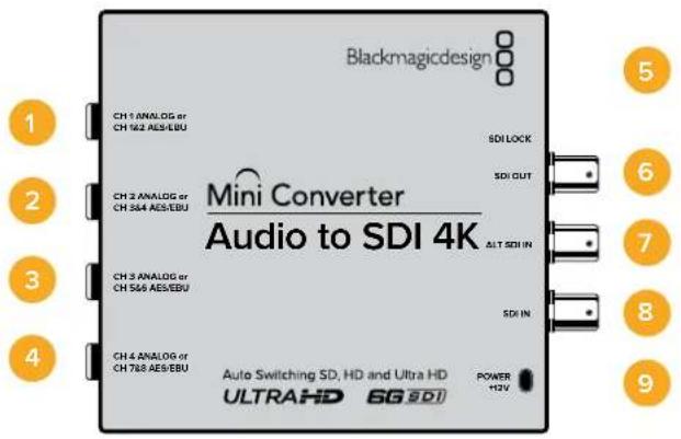
Connectors
1 CH 1 Analog or CH 1 & 2 AES/EBU
Balanced analog audio channel 1, or AES/EBU digital audio channels 1 and 2 input 1/4" jack connector.
2 CH 2 Analog or CH 3 & 4 AES/EBU
Balanced analog audio channel 2, or AES/EBU digital audio channels 3 and 4 input 1/4" jack connector.
3 CH 3 Analog or CH 5 & 6 AES/EBU
Balanced analog audio channel 3, or AES/EBU digital audio channels 5 and 6 input 1/4" jack connector.
4 CH 4 Analog or CH 7 & 8 AES/EBU
Balanced analog audio channel 4, or AES/EBU digital audio channels 7 and 8 input 1/4" jack connector.
5 Mini-B USB PORT
Connects to the Converters Setup software via your Mac OS X or Windows computer. The Mini Converter's internal software is also updated using the USB port.
6 SDI OUT
Loop through SDI video output on a BNC connector.
7 ALT SDI IN
Redundant SDI input provided as an optional back up. When using both the SDI IN and ALT SDI IN, the ALT SDI IN will take over should the SDI IN signal fail. The SDI LOCK LED will flash indicating that the converter has switched to the ALT SDI IN.
8 SDI IN
Primary SDI input.
9 POWER +12V
12 volt power supply input.
Switches
Mini Converter Audio to SDI 4K switches provide the following settings:
Switch 8 - Analog Audio, AES/EBU Audio
Set switch 8 to OFF to select balanced analog audio, or to ON for digital AES/EBU audio input.
Switch 7 - Sample Rate Conversion, No Sample Rate Conversion
Set switch 7 to OFF to enable sample rate conversion, or ON to disable sample rate conversion. This switch should almost always be set to OFF to ensure audio is embedded at the correct sample rate for television.
When switch 7 is set to OFF this setting converts the sample rate of your analog or AES/EBU audio and embeds audio into the SDI output at a sample rate of 48 kHz. When switch 7 is set to ON, sample rate conversion is disabled and audio is output at the original sample rate of your input audio.
Switch 6 - Audio Group Bit 1
Switches 6 and 5 are grouped together to provide four ON/OFF combinations. Having four different combinations allows up to four analog audio channels, or eight AES/EBU audio channels to be embedded in your SDI output.
Switch 5 - Audio Group Bit 0
See switch 6 description.
Audio Selection Table
| Analog Audio Channels Switch 6 Switch 5 Switch Diagram | |||
| 1 to 4 OFF OFF | ONOFF8 7 6 5 4 3 2 1 | ||
| 5 to 8 OFF ON | ONOFF8 7 6 5 4 3 2 1 | ||
| 9 to 12 ON OFF | ONOFF8 7 6 5 4 3 2 1 | ||
| 13 to 16 ON ON | ONOFF8 7 6 5 4 3 2 1 | ||
| AES/EBU Channels Switch 6 Switch 5 Switch Diagram | |||
| 1 to 8 OFF | OFF | ONOFF8 7 6 5 4 3 2 1 | |
| 9 to 16 OFF | ON | ONOFF8 7 6 5 4 3 2 1 | |
Embedding or Disabling Channels
Once you have selected your audio channels, use switches 4, 3, 2 and 1 to select which channels to embed or disable. The disable setting lets you avoid overwriting audio channels you wish to keep in the SDI signal.
For example, you can disable analog audio channel 1 or AES/EBU channels 1 and 2 by setting switch 1 to the ON position. Alternatively, you can embed the audio channels by setting switch 1 to the OFF position.
Audio Channel De-Embed or Disable Settings
| Switch Setting Audio Channels | |
| 4 | ON Disable analog CH 4, AES/EBU CH 7 and 8 |
| OFF Embed analog CH 4, AES/EBU CH 7 and 8 | |
| 3 | ON Disable analog CH 3, AES/EBU CH 5 and 6 |
| OFF Embed analog CH 3, AES/EBU CH 5 and 6 | |
| 2 | ON Disable analog CH 2, AES/EBU CH 3 and 4 |
| OFF Embed analog CH 2, AES/EBU CH 3 and 4 | |
| 1 | ON Disable analog CH 1, AES/EBU CH 1 and 2 |
| OFF Embed analog CH 1, AES/EBU CH 1 and 2 | |
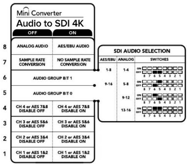
The switch legend on the base of your converter gives you all the information you need to change conversion settings.
Mini Switch Settings Example
Try experimenting with the switches. Select analog audio channels 1 to 4 by setting switches 8, 6 and 5 to the OFF position.
Blackmagic Converters Setup Settings
The Converters Setup utility can be used to change settings and update your Mini Converter's software. You can access these settings by moving between the 'audio,' and 'about' tabs.
The ‘about’ tab is detailed in the ‘changing settings’ section in this manual.
The ‘audio’ tab for Mini Converter Audio to SDI 4K contains the following settings.
Input Levels menu
This menu allows you to adjust the gain on the audio input. You can adjust audio levels independently per channel, or together as channel pairs by clicking the 'link' icon next to their sliders. To reset all audio levels back to 0 dB click the 'reset' button at the top of the 'output levels' menu.
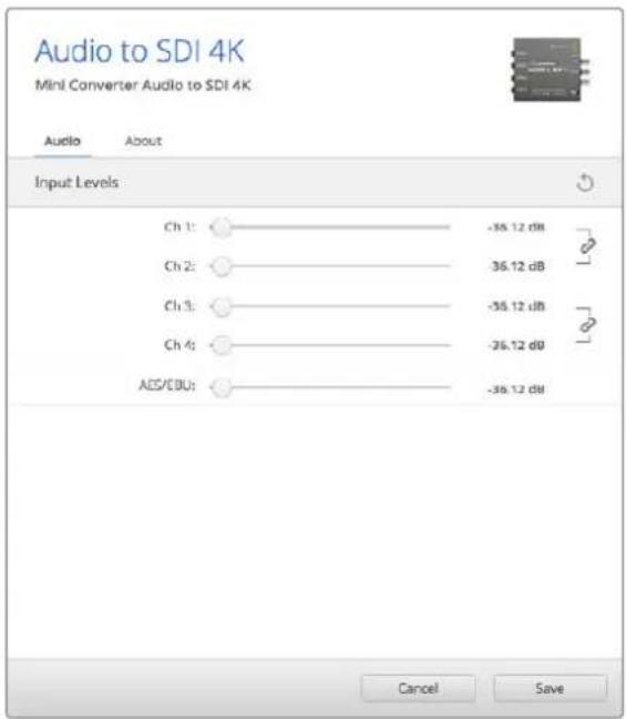
Use the 'audio' tab in Converters Setup to adjust analog audio levels.
Mini Converter Audio to SDI 4K Block Diagram
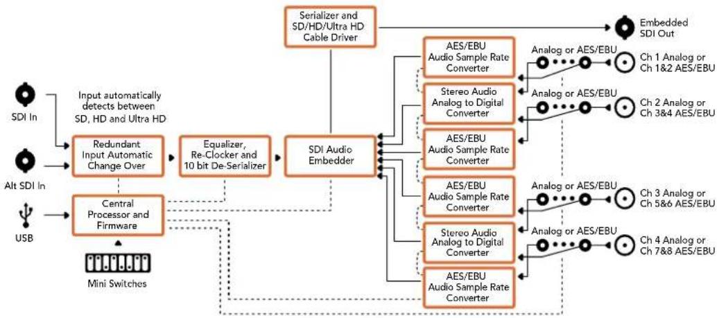
flowchart
graph TD
    A["SDI In"] --> B["Input automatically detects between SD, HD and Ultra HD"]
    C["Alt SDI In"] --> D["Central Processor and Firmware"]
    E["USB"] --> D
    B --> F["Redundant Input Automatic Change Over"]
    D --> G["Equalizer, Re-Clocker and 10 bit De-Serializer"]
    F --> H["SDI Audio Embedder"]
    G --> H
    H --> I["AES/EBU Audio Sample Rate Converter"]
    H --> J["Stereo Audio Analog to Digital Converter"]
    H --> K["AES/EBU Audio Sample Rate Converter"]
    H --> L["AES/EBU Audio Sample Rate Converter"]
    H --> M["Stereo Audio Analog to Digital Converter"]
    H --> N["AES/EBU Audio Sample Rate Converter"]
    I --> O["Analog or AES/EBU"]
    J --> P["Analog or AES/EBU"]
    K --> Q["Analog or AES/EBU"]
    L --> R["Analog or AES/EBU"]
    M --> S["Analog or AES/EBU"]
    N --> T["Analog or AES/EBU"]
    O --> U["Embedded SDI Out"]
    P --> U
    Q --> U
    R --> U
    S --> U
    T --> U
    U --> V["Mini Switches"]
Mini Converter Optical Fiber
With Mini Converter Optical Fiber you can convert SDI to Optical Fiber and Optical Fiber to SDI simultaneously. Mini Converter Optical Fiber automatically switches between SD/HD/3G-SDI video standards and both directions are completely independent. Use this converter if you need to send and receive SDI signals over longer distances than traditional SDI cables will support. SD video can be sent up to 45 km or 147000 feet using optical fiber, compared to just 300 feet with copper SDI cables. 3G-SDI can be sent up to 25 km away!
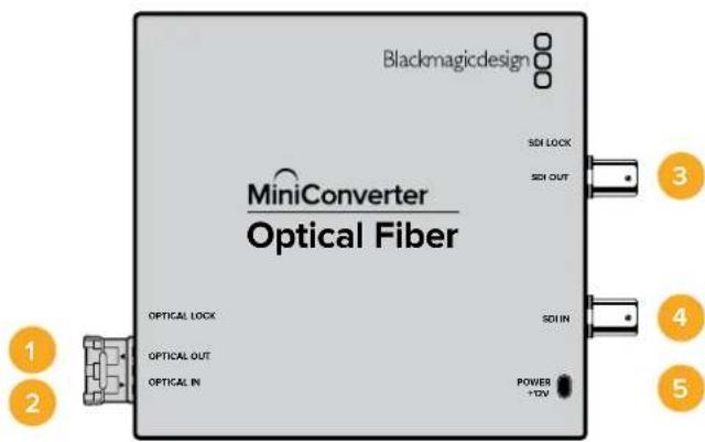
Connectors
1 Optical Out Optical fiber output supports a single mode optical fiber cable with LC connector.
2 Optical In
Optical fiber input supports a single mode optical fiber cable with LC connector.
3 3G-SDI Out SDI video output on a BNC connector for connection to traditional SDI equipment.
4 3G-SDI In
SDI input on a BNC connector for connection to traditional SDI equipment.
5 Power +12V
12 volt power supply input.
Mini Converter Optical Fiber Block Diagram
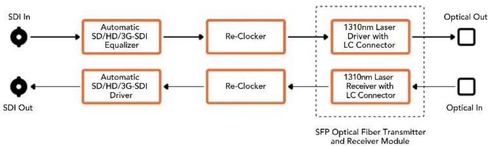
flowchart
graph LR
    A["SDI In"] --> B["Automatic SD/HD/3G-SDI Equalizer"]
    B --> C["Re-Clocker"]
    C --> D["1310nm Laser Driver with LC Connector"]
    D --> E["Optical Out"]
    F["SDI Out"] --> G["Automatic SD/HD/3G-SDI Driver"]
    G --> H["Re-Clocker"]
    H --> I["1310nm Laser Receiver with LC Connector"]
    I --> J["Optical In"]
    style A fill:#fff,stroke:#000
    style F fill:#fff,stroke:#000
    style D fill:#fff,stroke:#000
    style J fill:#fff,stroke:#000
Mini Converter Optical Fiber 4K
Convert SD/HD and single link 6G-SDI to Optical Fiber and Optical Fiber to SD/HD and single link 6G-SDI simultaneously. Mini Converter Optical Fiber 4K automatically switches between SD/HD/3G/6G-SDI video standards and both directions are completely independent. Use this converter if you need to send and receive SDI signals over longer distances than traditional SDI cables will support. SD video can be sent up to 45 km or 147000 feet using optical fiber, compared to just 300 feet with copper SDI cables. 6G-SDI can be sent up to 12 km away!
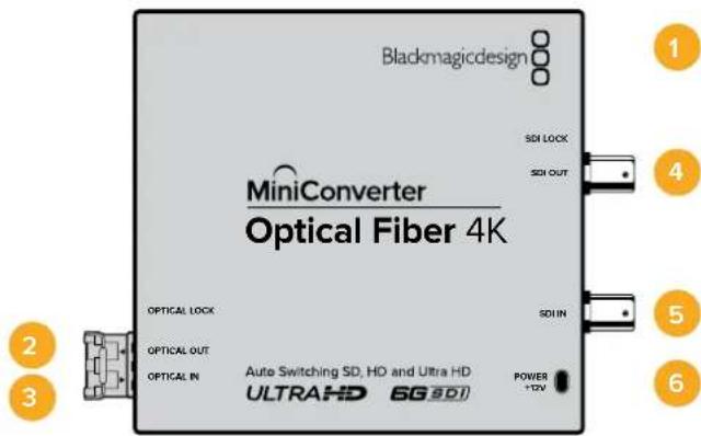
Connectors
1 Mini-B USB Port
The Mini Converter's internal software is updated using the USB port.
2 Optical Out
Optical fiber output supports a single mode optical fiber cable with LC connector.
3 Optical In
Optical fiber input supports a single mode optical fiber cable with LC connector.
4 SDI Out
SDI video output on a BNC connector for connection to traditional SDI equipment.
5 SDI In
SDI input on a BNC connector for connection to traditional SDI equipment.
6 Power +12V
12 volt power supply input.
Mini Converter Optical Fiber 4K Block Diagram
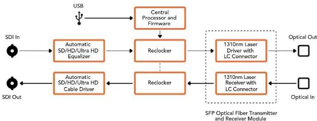
flowchart
graph TD
    A["USB"] --> B["Central Processor and Firmware"]
    B --> C["Reclocker"]
    C --> D["1310nm Laser Driver with LC Connector"]
    D --> E["Optical Out"]
    F["SDI In"] --> G["Automatic SD/HD/Ultra HD Equalizer"]
    G --> H["Reclocker"]
    I["SDI Out"] --> J["Automatic SD/HD/Ultra HD Cable Driver"]
    J --> K["Reclocker"]
    K --> L["1310nm Laser Receiver with LC Connector"]
    L --> M["Optical In"]
    N["SFP Optical Fiber Transmitter and Receiver Module"] -.-> L
Mini Converter Optical Fiber 12G
This converter converts SD and HD video up to 12G-SDI to optical fiber and the other way around simultaneously.
The socket for the SFP type optical fiber module can be fitted with a compatible SFP optical fiber module that supports up to 3G, 6G or 12G-SDI video.
Your converter automatically detects the video input format and sets the output format to match. Both directions are completely independent.
This converter is helpful if you need to send and receive SDI signals over longer distances than traditional SDI cables will support. For example, SD video can be sent up to 45 km or 147,000 feet using optical fiber, compared to just 300 feet with copper SDI cables. 12G-SDI can be sent up to 6 km away!
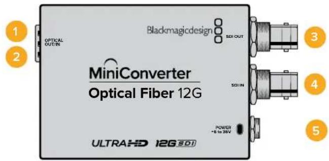
Connectors
1 Optical Out
Optical fiber output supports a single mode optical fiber cable with LC connector.
2 Optical In
Optical fiber input supports a single mode optical fiber cable with LC connector.
3 SDI Out
SDI video output on a BNC connector for connection to SDI equipment.
4 SDI In
SDI input on a BNC connector for connection to SDI equipment.
5 Power +6 to 36V
6-36 volt power supply input. The support screw can be secured to the unit's power connector to prevent accidental disconnection.
Mini Converter Optical Fiber 12G Block Diagram
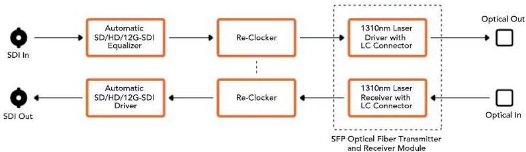
flowchart
graph LR
    A["SDI In"] --> B["Automatic SD/HD/12G-SDI Equalizer"]
    B --> C["Re-Clocker"]
    C --> D["1310nm Laser Driver with LC Connector"]
    D --> E["Optical Out"]
    F["SDI Out"] --> G["Automatic SD/HD/12G-SDI Driver"]
    G --> H["Re-Clocker"]
    H --> I["1310nm Laser Receiver with LC Connector"]
    I --> J["Optical In"]
    style A fill:#fff,stroke:#000
    style F fill:#fff,stroke:#000
    style E fill:#fff,stroke:#000
    style J fill:#fff,stroke:#000
Mini Converter Quad SDI to HDMI 4K
Your Mini Converter Quad SDI to HDMI 4K can connect single link, dual link and quad link SDI Ultra HD to the latest Ultra HD projectors and televisions that support Ultra HD over a single HDMI link. You can also convert any of the following inputs to HDMI:
SD SDI
HD-SDI
- Singlelink 3G-SDI
- Singlelink 6G-SDI
- Duallink HD-SDI
- Dual link 3G-SDI Ultra HD
- Quad link HD-SDI Ultra HD
If the HDMI output detects an HD monitor or HDTV, the output signal is automatically downconverted. Only use inputs 1 and 2 with a valid dual link signal.
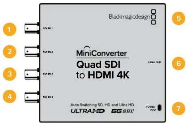
Connectors
Supported formats are listed under each SDI input:
1 SDI In 1
SD/HD-SDI
- Single link 3G-SDI
- Single link 6G-SDI
- Dual link HD-SDI channel A
• Dual link 3G-SDI Ultra HD channel A
- Quad link HD-SDI Ultra HD channel A
2 SDI In 2
- Dual link HD-SDI channel B
- Dual link 3G-SDI Ultra HD channel B
- Quad link HD-SDI Ultra HD channel B
3 SDI In 3
- Quad link HD-SDI Ultra HD channel C
4 SDI In 4
- Quad link HD-SDI Ultra HD channel D
5 Mini-B USB port
Connects to the Converters Setup software via your Mac OS X or Windows computer. The Mini Converter's internal software is also updated using the USB port.
6 HDMI
HDMI type A video output.
7 Power +12V
12 volt power supply input.
Mini Converter Quad SDI to HDMI 4K Block Diagram
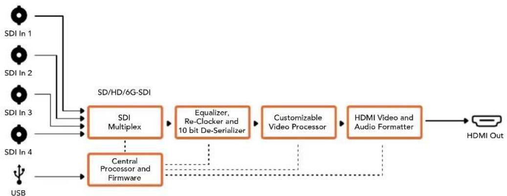
flowchart
graph LR
    A["SDI In 1"] --> D["SDI Multiplex"]
    B["SDI In 2"] --> D
    C["SDI In 3"] --> D
    E["SDI In 4"] --> D
    F["USB"] --> G["Central Processor and Firmware"]
    D --> H["Equalizer, Re-Clocker and 10 bit De-Serializer"]
    H --> I["Customizable Video Processor"]
    I --> J["HDMI Video and Audio Formatter"]
    J --> K["HDMI Out"]
    D -.-> G
Mini Converter SDI Distribution
With Mini Converter SDI Distribution you can output your SDI signal to eight SDI devices simultaneously, such as decks, monitor walls and switchers. Whenever the video input changes between SD-SDI, HD-SDI and 3G-SDI video formats, Mini Converter SDI Distribution automatically switches the 8 re-clocked outputs to match with support for ASI, ancillary data and embedded audio formats.
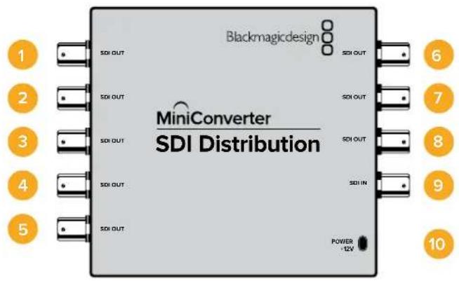
Connectors
1-8 SDI Out
SDI video outputs on BNC connectors.
9SDIn
SDI input.
10 Power +12V
12 volt power supply input.
Mini Converter SDI Distribution Block Diagram
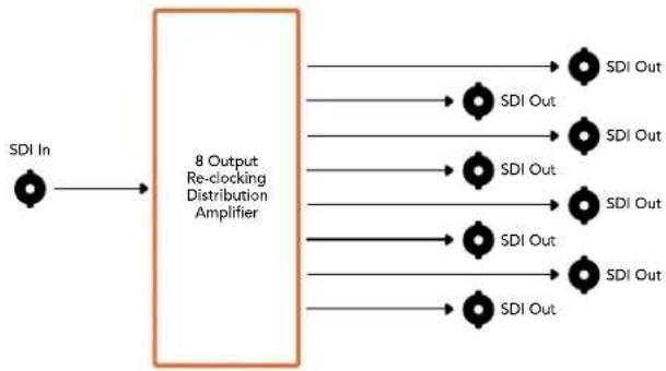
flowchart
graph LR
    A["SDI In"] --> B["8 Output Re-clocking Distribution Amplifier"]
    B --> C1["SDI Out"]
    B --> C2["SDI Out"]
    B --> C3["SDI Out"]
    B --> C4["SDI Out"]
    B --> C5["SDI Out"]
    B --> C6["SDI Out"]
    B --> C7["SDI Out"]
Mini Converter SDI Distribution 4K
Your Mini Converter SDI Distribution 4K outputs your SDI signal to eight SDI devices simultaneously, such as decks, monitor walls and switchers. Whenever the video input changes between SD/HD/3G/6G-SDI video formats, Mini Converter SDI Distribution 4K automatically switches the 8 re-clocked outputs to match, with support for ASI, ancillary data and embedded audio formats.
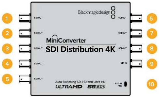
Connectors
1-8 SDI Out
SDI video outputs on BNC connectors.
9SDIn
SDI input.
10 Power +12V
12 volt power supply input.
Mini Converter SDI Distribution 4K Block Diagram
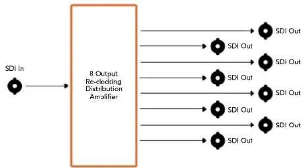
flowchart
graph LR
    A["SDI In"] --> B["8 Output Re-clocking Distribution Amplifier"]
    B --> C1["SDI Out"]
    B --> C2["SDI Out"]
    B --> C3["SDI Out"]
    B --> C4["SDI Out"]
    B --> C5["SDI Out"]
    B --> C6["SDI Out"]
    B --> C7["SDI Out"]
    B --> C8["SDI Out"]
Mini Converter SDI Multiplex 4K
Your Mini Converter SDI Multiplex 4K can perform the following conversions:
- Distribute an SD/HD and 6G-SDI signal to all four outputs.
- Distribute a dual link HD-SDI signal to all four 3G-SDI outputs.
- Single link 3G-SDI to dual link HD-SDI. The dual link output is distributed on both pairs of outputs.
- Single link 6G-SDI to dual link 3G-SDI or Quad link 1.5G-SDI.
- Quad link HD-SDI Ultra HD to single link 6G-SDI, or dual link 3G-SDI Ultra HD so you can connect existing Ultra HD sources to dual link Ultra HD displays. The dual link output is distributed on both pairs of outputs.
- Dual link 3G-SDI to single link 6G-SDI.
- Dual link 3G-SDI Ultra HD to quad link HD-SDI Ultra HD so you can connect the latest dual link Ultra HD sources to existing quad link Ultra HD displays.
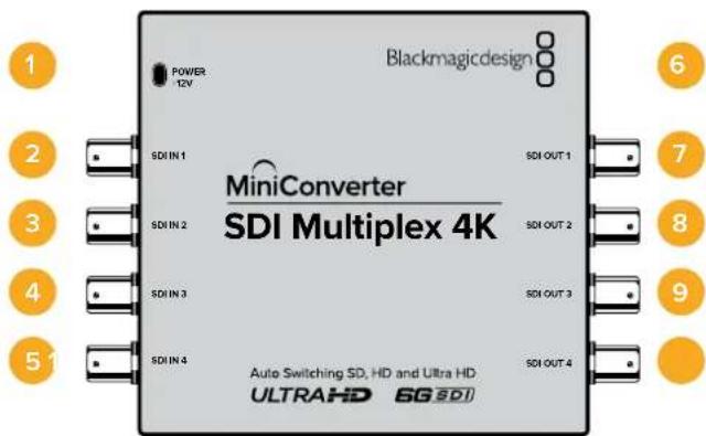
Connectors
1 Power +12V
- 12 volt power supply input
• Supported formats for each SDI input
2 SDI In 1
SD/HD-SDI
- Single link 3G-SDI
- Single link 6G-SDI
- Dual link HD-SDI channel A
- Dual link 3G-SDI Ultra HD channel A
• Quad link HD-SDI Ultra HD channel A
3 SDI In 2
- Dual link HD-SDI channel B
- Dual link 3G-SDI Ultra HD channel B
• Quad link HD-SDI Ultra HD channel B
4 SDI In 3
- Quad link HD-SDI Ultra HD channel C
5 SDI In 4
• Quad link HD-SDI Ultra HD channel D
6 Mini-B USB port
Connects to the Converters Setup software via your Mac OS X or Windows computer.
The Mini Converter's internal software can also be updated using the USB port.
Supported formats are listed under each SDI output:
7 SDI Out 1
SD/HD-SDI
- Single link 3G-SDI
- Single link 6G-SDI
- Dual link HD-SDI channel A
- Dual link 3G-SDI Ultra HD channel A
- Quad link HD-SDI Ultra HD channel A
8 SDI Out 2
SD/HD-SDI
- Single link 3G-SDI
- Single link 6G-SDI
- Dual link HD-SDI channel B
- Dual link 3G-SDI Ultra HD channel B
- Quad link HD-SDI Ultra HD channel B
9 SDI Out 3
SD/HD-SDI
- Single link 3G-SDI
- Single link 6G-SDI
- Dual link HD-SDI channel A
- Dual link 3G-SDI Ultra HD channel A
- Quad link HD-SDI Ultra HD channel C
10 SDI Out 4
SD/HD-SDI
- Single link 3G-SDI
- Single link 6G-SDI
- Dual link HD-SDI channel B
- Dual link 3G-SDI Ultra HD channel B
• Quad link HD-SDI Ultra HD channel D
Switches
Mini Converter SDI Multiplex 4K's switches provide the following settings:
Switches 8, 7 and 6 - Format Conversion
Combinations of switches 8, 7 and 6 set conversions such as dual link HD-SDI to single link HD-SDI, or quad link Ultra HD to single link Ultra HD.
Switch 1 - Processing ON/OFF
When switch 1 is set to OFF, Mini Converter SDI Multiplex 4K acts as a 4 output SD/HD/6G-SDI distribution amplifier.
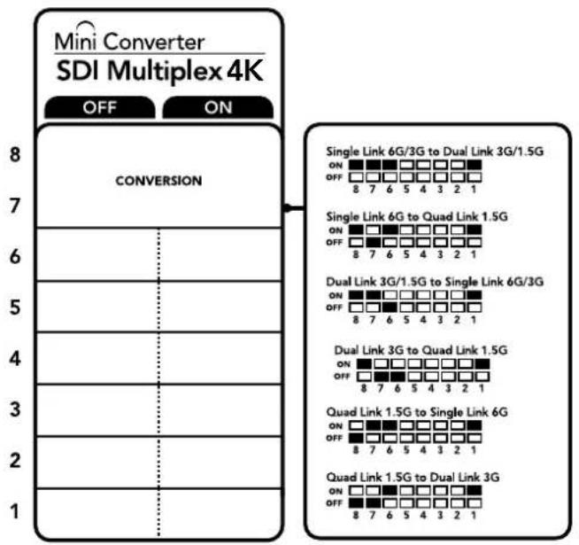
flowchart
graph TD
    A["MINI Converter SDI Multiplex 4K"] --> B["CONVERSION"]
    B --> C["Single Link 6G/3G to Dual Link 3G/1.5G"]
    B --> D["Single Link 6G to Quad Link 1.5G"]
    B --> E["Dual Link 3G/1.5G to Single Link 6G/3G"]
    B --> F["Dual Link 3G to Quad Link 1.5G"]
    B --> G["Quad Link 1.5G to Single Link 6G"]
    B --> H["Quad Link 1.5G to Dual Link 3G"]
The switch legend on the base of your converter gives you all the information you need to change conversion settings.
Mini Switch Settings Example
Convert quad link Ultra HD to dual link Ultra HD by setting switch 8 to ON, and switch 7 to OFF.
SDI Connection Table
| Conversion Switch 8 Switch 7 Switch 6 Switch 1 Switch Diagram | ||||
| Single Link 6G/3G-SDI to Dual Link 3G/1.5G-SDI | ON ON | ON ON | 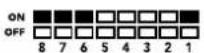 | |
| Single Link 6G-SDI to Quad Link 1.5G-SDI | ON OFF | ON ON | 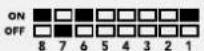 | |
| Dual Link 3G/1.5G-SDI to Single Link 6G/3G-SDI | ON ON | OFF ON | 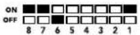 | |
| Dual Link 3G-SDI to Quad Link 1.5G-SDI | ON OFF | OFF ON | 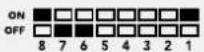 | |
| Quad Link 1.5G-SDI to Single Link 6G-SDI | OFF ON | ON ON | 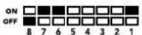 | |
| Quad Link 1.5G-SDI to Dual Link 3G-SDI | OFF OFF | ON ON | 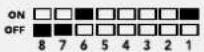 | |
Mini Converter SDI Multiplex 4K Block Diagram
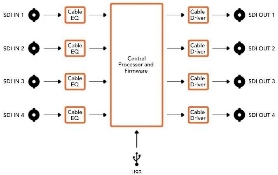
flowchart
graph LR
    A["SDI IN 1"] --> B["Cable EQ"]
    C["SDI IN 2"] --> D["Cable EQ"]
    E["SDI IN 3"] --> F["Cable EQ"]
    G["SDI IN 4"] --> H["Cable EQ"]
    B --> I["Central Processor and Firmware"]
    D --> I
    F --> I
    H --> I
    I --> J["Cable Driver"]
    I --> K["Cable Driver"]
    I --> L["Cable Driver"]
    I --> M["Cable Driver"]
    J --> N["SDI OUT 1"]
    K --> O["SDI OUT 2"]
    L --> P["SDI OUT 3"]
    M --> Q["SDI OUT 4"]
    R["ISR"] --> I
Mini Converter Sync Generator
Your Mini Converter Sync Generator includes 6 crystal stabilized video reference outputs for locking your video equipment to a common reference signal. Sync Generator produces high definition tri-sync or standard definition blackburst signals and is perfect for small studios and outside broadcasts.
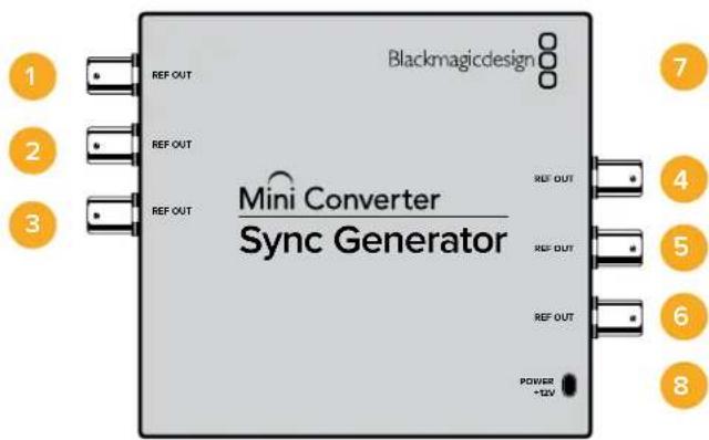
Connectors
1-6 REF Out
Reference video outputs BNC connectors.
7 Mini-B USB port
Connects to the Converters Setup software via your Mac OS X or Windows computer. The Mini Converter's internal software is also updated using the USB port.
8 Power+12V
12 volt power supply input.
Switches
Mini Converter Sync Generator's switches provide the following settings:
Switch 4, 3, 2 and 1 - SYNC REF FORMAT BIT 3, 2, 1 and 0
Switches 4, 3, 2 and 1 are grouped together to select from many reference video formats, including:
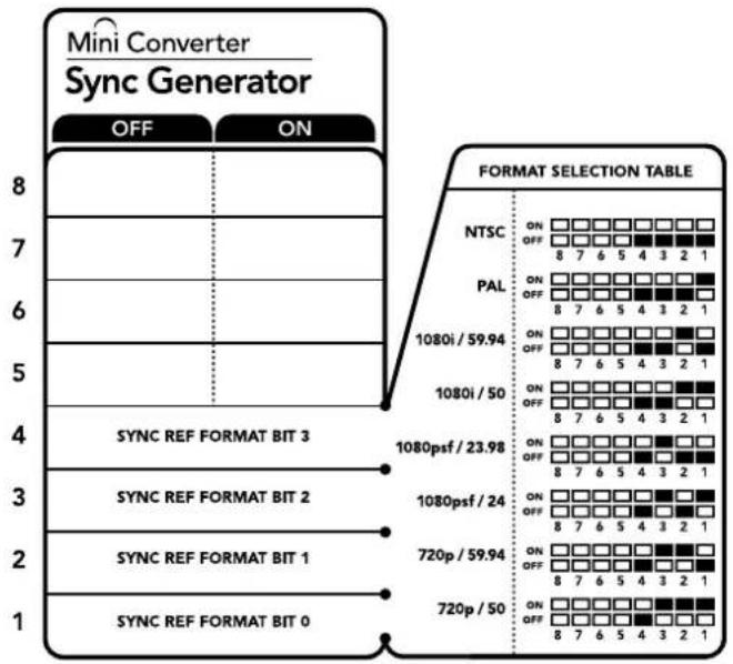
The switch legend on the base of your converter gives you all the information you need to change conversion settings.
Video Format Selection Table
| Video Format Switch 4 Switch 3 Switch 2 Switch 1 Switch Diagram | |||||
| NTSC OFF OFF OFF OFF | ONOFF8 7 6 5 4 3 2 1 | ||||
| PAL OFF OFF OFF ON | ONOFF8 7 6 5 4 3 2 1 | ||||
| 720p50 OFF ON ON ON | ONOFF8 7 6 5 4 3 2 1 | ||||
| 720p59.94 OFF ON ON OFF | ONOFF8 7 6 5 4 3 2 1 | ||||
| 720p60 ON ON ON OFF | ONOFF8 7 6 5 4 3 2 1 | ||||
| 1080i50 OFF OFF ON ON | ONOFF8 7 6 5 4 3 2 1 | ||||
| 1080i59.94 OFF ON OFF | ONOFF8 7 6 5 4 3 2 1 | ||||
| 1080i60 ON OFF OFF OFF | ONOFF8 7 6 5 4 3 2 1 | ||||
| 1080PsF23.98 OFF ON OFF OFF | ONOFF8 7 6 5 4 3 2 1 | ||||
| 1080PsF24 OFF ON OFF ON | ONOFF8 7 6 5 4 3 2 1 | ||||
| 1080p23.98 ON ON OFF ON | ONOFF8 7 6 5 4 3 2 1 | ||||
| 1080p24 ON ON OFF OFF | ONOFF8 7 6 5 4 3 2 1 | ||||
| 1080p25 | ON OFF ON ON | ONOFF8 7 6 5 4 3 2 1 | |||
| 1080p29.97 | ON | OFF | ON | OFF | ONOFF8 7 6 5 4 3 2 1 |
| 1080p30 | ON | OFF | OFF | ON | ONOFF8 7 6 5 4 3 2 1 |
Mini Converter Sync Generator Block Diagram
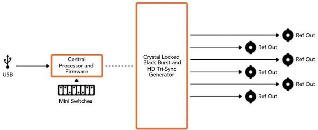
flowchart
graph LR
    A["USB"] --> B["Central Processor and Firmware"]
    B --> C["Mini Switches"]
    C -.-> D["Crystal Locked Black Burst and HD Tri-Sync Generator"]
    D --> E["Ref Out"]
    D --> F["Ref Out"]
    D --> G["Ref Out"]
    D --> H["Ref Out"]
    D --> I["Ref Out"]
Mini ConverterUpDownCross
Your Mini Converter UpDownCross performs up, down and cross conversions as well as NTSC/PAL standards conversion and format conversion. Mini Converter UpDownCross can convert between video formats such as 720p to 1080i and PAL and NTSC video standards. It also provides up conversions with aspect ratios such as 4:3 Pillarbox and 16:9 zoom, and down conversion options such as letterbox 4:3 and anamorphic 16:9.
When conversion processing is set to OFF, the Mini Converter acts as an SDI distribution amplifier.
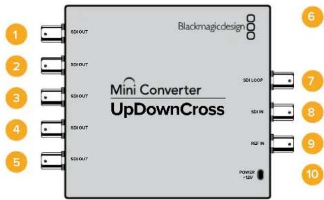
Connectors
1-5 SDI Out
SDI video outputs BNC connectors.
6 Mini-B USB port
Connects to the Converters Setup software via your Mac OS X or Windows computer. The Mini Converter's internal software is also updated using the USB port.
7 SDI LOOP
Direct output of your input video.
8 SDI IN
SDI Input.
9 REF IN
Reference video input.
10 Power +12V
12 volt power supply input.
Switches
Mini ConverterUpDownCross' switches provide the following settings:
Switch 8 - Aspect Ratio Conversion
Combinations of switches 8 and 7 set the video aspect ratio when up or down converting. For example, when down converting, the letterbox aspect ratio is applied by setting switches 8 and 7 to the OFF position.
Aspect Ratio Conversion Table
| Down conversion Switch 8 Switch 7 Switch Diagram | |||
| Letterbox | 16:9 Ratio Image 4:3 Ratio Display | OFF OFF | ON OFF 8 7 6 5 4 3 2 1 |
| Anamorphic | 16:9 Ratio Image 4:3 Ratio Display | OFF ON | ON OFF 8 7 6 5 4 3 2 1 |
| Center Cut | 16:9 Ratio Image 4:3 Ratio Display | ON ON | ON OFF 8 7 6 5 4 3 2 1 |
| Up conversion Switch 8 Switch 7 Switch Diagram | |||
| 4:3 Pillarbox | 16:9 Ratio Display4:3 Ratio Image | OFF OFF | ON OFF 8 7 6 5 4 3 2 1 |
| 14:9 Pillarbox | 4:3 Ratio Image 16:9 Ratio Display | OFF ON | ON OFF 8 7 6 5 4 3 2 1 |
| 16:9 De-Squeeze | 4:3 Ratio Display 16:9 Ratio Image | ON ON | ON OFF 8 7 6 5 4 3 2 1 |
You've probably noticed switches 8 and 7 share settings for up and down conversions. This is because aspect ratio settings are determined by the output settings. For example, if you have switches 3 and 2 set for 1080i50 HD output, and processing switch 1 set to ON, Mini Converter UpDownCross will automatically set switches 8 and 7 for down conversion.
Below is a description for each aspect ratio conversion:
Up conversion
- 4:3 Pillarbox: This setting displays 4:3 standard definition inside a high definition 16:9 frame. Black bars feature on the sides.
- 14:9 Pillarbox: This setting is a compromise between 4:3 pillarbox and 16:9 zoom. The standard definition 4:3 image is slightly zoomed into, allowing more image in the 16:9 frame and reducing the amount of black bars on the sides, but slightly losing the top and bottom.
- 16:9 De-Squeeze: This setting de-squeezes the standard definition 4:3 anamorphic image until it completely fills the 16:9 frame. None of the 4:3 image is lost.
Down conversion
- Letterbox: This setting scales the entire 16:9 HD image into a 4:3 SD frame without squeezing, leaving black bars on the top and bottom.
- Anamorphic: This setting horizontally squeezes the 16:9 HD image into a 4:3 SD frame.
- Center Cut: This setting cuts a 4:3 SD frame from the 16:9 HD image. This aspect ratio setting discards a portion from each side of the 16:9 image.
Switch 1 - Processing Off - Processing On
When switch 1 is set to OFF all conversions are bypassed and the Mini Converter can be used to distribute your video to six SDI devices.
Mini Switch Settings Example:
Set the converter to up convert 4:3 625i50 video to 1080i50 with the 4:3 Pillarbox aspect ratio by setting switches 8 and 7 to the OFF position and switches 3, 2 and 1 to the ON position.
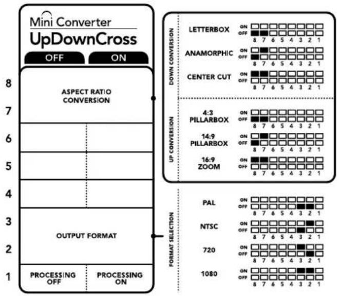
other
Mini Converter UpDownCross | Category | Label | | :--- | :--- | | Left Panel | ASPECT RATIO CONVERSION | | Middle Panel | LETTERBOX ON OFF 8 7 6 5 4 3 2 1 Middle Panel | ANAMORPHIC ON OFF 8 7 6 5 4 3 2 1 Middle Panel | CENTER CUT ON OFF 8 7 6 5 4 3 2 1 Right Panel | UP CONVERSION 4:3 PILLARBOX ON OFF 8 7 6 5 4 3 2 1 Right Panel | 14:9 PILLARBOX ON OFF 8 7 6 5 4 3 2 1 Right Panel | 16:9 ZOOM ON OFF 8 7 6 5 4 3 2 1 Bottom Panel | OUTPUT FORMAT | Bottom Panel | PAL ON OFF 8 7 6 5 4 3 2 1 Bottom Panel | NTSC ON OFF 8 7 6 5 4 3 2 1 Bottom Panel | 720 ON OFF 8 7 6 5 4 3 2 1 Bottom Panel | 1080 ON OFF 8 7 6 5 4 3 2 1The switch legend on the base of your converter gives you all the information you need to change conversion settings.
Mini ConverterUpDownCross Conversion Table
| Input Video | NTSCSwitches1 and 2 ON | PALSwitch1 ON | 720pSwitches1 and 3 ON | 1080Switches1, 2 and 3 ON |
| 525i59.94 525i59.94 625i50 720p59.94 1080i59.94 | ||||
| 625i50 525i59.94 625i50 720p50 1080i50 | ||||
| 720p50 525i59.94 625i50 720p50 1080i50 | ||||
| 720p59.94 525i59.94 625i50 720p59.94 1080i59.94 | ||||
| 720p60 525i59.94 625i50 720p60 1080i60 | ||||
| 1080PsF23.98 | 525i59.94 | 625i50 | 720p59.94 | 1080PsF23.98 |
| 1080p23.98 | 525i59.94 | 625i50 | 720p59.94 | 1080p23.98 |
| 1080PsF24 525i59.94 625i50 720p50 1080PsF24 | ||||
| 1080p24 | 525i59.94 | 625i50 | 720p50 | 1080p24 |
| 1080p25 | 525i59.94 | 625i50 | 720p50 | 1080p25 |
| 1080p29.97 | 525i59.94 | 625i50 | 720p59.94 | 1080p29.97 |
| 1080p30 | 525i59.94 | 625i50 | 720p60 | 1080p30 |
| 1080i50 525i59.94 625i50 720p50 1080i50 | ||||
| 1080i59.94 | 525i59.94 | 625i50 | 720p59.94 | 1080i59.94 |
| 1080i60 525i59.94 625i50 720p60 1080i60 | ||||
| 1080p50 | 525i59.94 | 625i50 | 720p50 | 1080p50 |
| 1080p59.94 | 525i59.94 | 625i50 | 720p59.94 | 1080p59.94 |
| 1080p60 | 525i59.94 | 625i50 | 720p60 | 1080p60 |
| 2048x1556PsF23.98 | 525i59.94 | 625i50 | 2048x1556PsF23.98 | 2048x1556PsF23.98 |
| 2048x1556PsF24 | 525i59.94 | 625i50 | 2048x1556PsF24 | 2048x1556PsF24 |
| 2048x1556PsF25 | 525i59.94 | 625i50 | 2048x1556PsF25 | 2048x1556PsF25 |
Mini ConverterUpDownCross Block Diagram
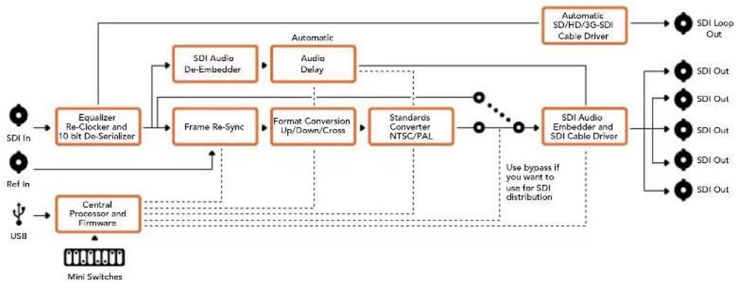
flowchart
graph TD
    A["SDI In"] --> B["Equalizer Re-Clocker and 10 bit De-Serializer"]
    C["Ref In"] --> B
    D["USB"] --> E["Central Processor and Firmware"]
    B --> F["Frame Re-Sync"]
    F --> G["Format Conversion Up/Down/Cross"]
    G --> H["Standards Converter NTSC/PAL"]
    H --> I["SDI Audio Embedding and SDI Cable Driver"]
    I --> J["SDI Loop Out"]
    B --> K["SDI Audio De-Embedder"]
    K --> L["Audio Delay"]
    L --> M["Automatic SDI/HD/3G-SDI Cable Driver"]
    M --> N["SDI Out"]
    E --> O["SDI Audio Embedding and SDI Cable Driver"]
    O --> P["SDI Out"]
    style A fill:#f9f,stroke:#333
    style C fill:#f9f,stroke:#333
    style D fill:#f9f,stroke:#333
    style B fill:#ccf,stroke:#333
    style E fill:#ccf,stroke:#333
    style F fill:#ccf,stroke:#333
    style G fill:#ccf,stroke:#333
    style H fill:#ccf,stroke:#333
    style I fill:#ccf,stroke:#333
    style J fill:#ccf,stroke:#333
    style K fill:#ccf,stroke:#333
    style L fill:#ccf,stroke:#333
    style M fill:#ccf,stroke:#333
    style N fill:#ccf,stroke:#333
    style O fill:#ccf,stroke:#333
    style P fill:#ccf,stroke:#333
Mini ConverterUpDownCross HD
Mini Converter UpDownCross HD is a powerful standards converter that gives you the ability to convert any SD or HD video format with up, down, or cross conversion via SDI and HDMI. This converter supports all SD and HD formats up to 1080p60 plus NTSC and PAL with aspect ratio options for up and down conversions. The HDMI input also accepts 1024 x 768, 800 x 600, and 640 x 480 computer output resolutions.
When conversion processing is set to OFF the HDMI and SDI outputs become loop outputs so you can feed the input signal to other HDMI and SDI equipment.
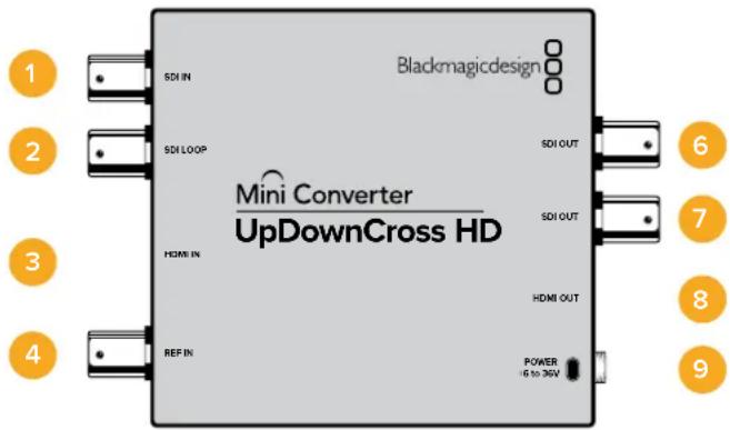
Connectors
1 SDI IN
SDI input. The small LED next to the BNC connector illuminates when a locked SDI signal is detected. When both SDI and HDMI inputs are connected, the SDI input takes priority.
2 SDI LOOP
Direct loop output of your SDI input video.
3 HDMI IN
HDMI type A video input. A small LED next to the HDMI IN connector illuminates to show when it detects a valid HDMI input.
4 REF IN
Reference video input. A small LED next to the REF IN connector indicates the reference lock status:
Constant white - the REF IN matches the format of the output video format set on the converter.
Flashing white - the REF IN is a valid video format but doesn't match the output video format set on the converter.
5 USB-C PORT
Connects to the Converters Setup software via your Mac OS X or Windows computer. The Mini Converter's internal software is also updated using the USB port.
6-7 SDI OUT
SDI video output BNC connectors.
8 HDMIOUT
HDMI type A video output.
9 POWER +6 to 36V
6 to 36 volt power supply input. The support screw can be secured to the unit's power connector to prevent accidental disconnection. A small LED next to the DC input jack illuminates to show when power is connected.
Switches
Mini ConverterUpDownCross HD's switches provide the following settings :
Switch 1 - Processing Off - Processing On
When switch 1 is set to OFF all conversions are bypassed and the converter can be used to distribute your video via both SDI and HDMI outputs.
With switch 1 set to OFF the SDI and HDMI outputs match their corresponding inputs.
When switch 1 is set to ON, processing is enabled and switches 4 to 8 configure the converter's output.
Switch 2 - Level A and Level B 3G-SDI
When switch 2 is set to OFF the converter outputs level B 3G-SDI. When set to ON the converter outputs level A 3G-SDI. This provides compatibility with other SDI equipment that uses level A or level B 3G-SDI.
TIP If you have connected a 3G-SDI signal to 3G-SDI equipment and the signal is not being detected, try changing the setting for switch 2 as the equipment you're connected to may be using an alternate SDI level.
Switches 4 - 8
Switches 4 to 8 determine the format and standard of the converter's output signal. The switch configuration for each format and standard is shown on the table on the base of the unit.
Mini Switch Settings Example:
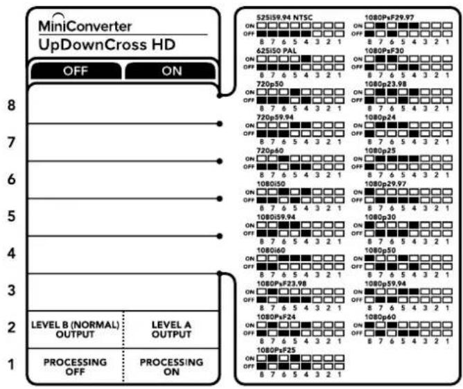
bar_stacked
| Level | OFF | ON | |-------|-----|----| | 1 | | 1080PpF25 | | 2 | | 1080PpF24 | | 3 | | 1080PpF23 | | 4 | | 1080PpF22 | | 5 | | 1080PpF21 | | 6 | | 1080PpF20 | | 7 | | 1080PpF19 | | 8 | | 1080PpF18 |Video Format Selection Table
| Video Format | Switch 8 | Switch 7 | Switch 6 | Switch 5 | Switch 4 | Switch Diagram |
| 525i59.94 NTSC | OFF OFF | OFF OFF | OFF | 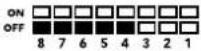 | ||
| 625i50 PAL OFF | OFF OFF | OFF ON | 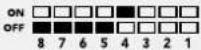 | |||
| 720p50 OFF | OFF ON | OFF | 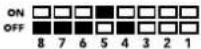 | |||
| 720p59.94 | OFF OFF | OFF ON | ON | 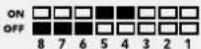 | ||
| 720p60 OFF | OFF ON | OFF ON | 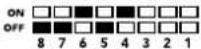 | |||
| 1080i50 | OFF OFF | ON OFF | ON | 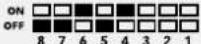 | ||
| 1080i59.94 | OFF OFF | ON ON | OFF | 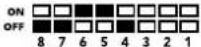 | ||
| 1080i60 | OFF OFF | ON ON | ON | 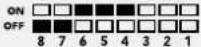 | ||
| 1080PsF23.98 | OFF ON | OFF | OFF | 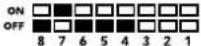 | ||
| 1080PsF24 | OFF ON | OFF OFF | ON | 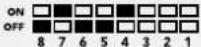 | ||
| 1080PsF25 | OFF | ON | OFF | ON | OFF | 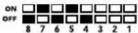 |
| 1080PsF29.97 | OFF | ON | OFF | ON | ON | 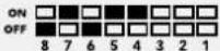 |
| 1080PsF30 | OFF ON | ON OFF | OFF | 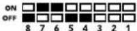 | ||
| 1080p23.98 | OFF | ON | ON | OFF | ON | 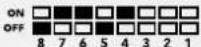 |
| 1080p24 | OFF | ON | ON | ON | OFF | 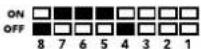 |
| 1080p25 | OFF ON | ON ON | ON | 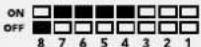 | ||
| 1080p29.97 | OFF | ON | ON | ON | OFF | 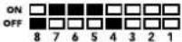 |
| 1080p30 | ON | OFF | OFF | OFF | ON | 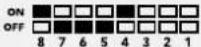 |
| 1080p50 | ON | OFF | OFF | ON | OFF | 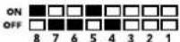 |
| 1080p59.94 ON | OFF | OFF ON | ON | 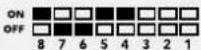 | ||
| 1080p60 | ON | OFF | ON | OFF | OFF | 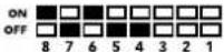 |
Converter Setup Utility
The Blackmagic Converters Setup utility can be used to change settings such as aspect ratio, and update your Mini Converter's software. All utility settings are maintained, even when the Mini Converter is switched off. You can access these settings by moving between the 'video,' 'audio,' and 'about' tabs.
The 'about' tab is detailed in the 'changing settings' section in this manual.
The 'video' tab for Mini ConverterUpDownCross HD contains the following settings:
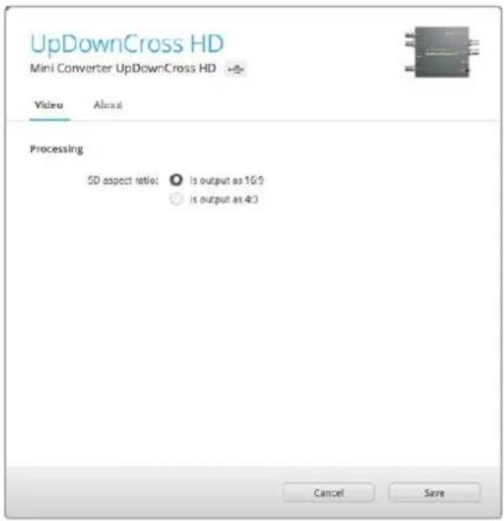
Use the 'video' tab in Converters Setup to select an SD aspect ratio.
Aspect Ratio for Standard Definition
Select an option for the aspect ratio of the SD output. You can choose 4:3 pillar boxed or 16:9. For example, if your input video is SD 4:3 then selecting 4:3 will output 4:3 pillar boxed to maintain the original 4:3 aspect ratio inside the 16:9 frame. However, if your input video is SD 16:9 select the 16:9 option to output a direct 16:9 conversion.
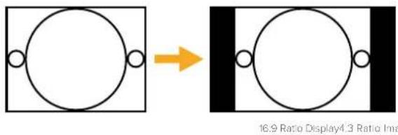
The default aspect ratio setting in the setup utility will output SD video as pillar boxed 4:3, however, you can set the converter to maintain a 16:9 ratio if required by selecting the 16:9 option on the 'video' tab of the setup utility.
Blackmagic Battery Converters
Battery Converter SDI to HDMI
With Battery Converter SDI to HDMI you can connect a huge range of HDMI displays and video projectors to SDI based equipment. Your Battery Converter SDI to HDMI automatically detects between SD/HD/3G-SDI and converts to HDMI with embedded audio. Battery Converter SDI to HDMI includes a built in rechargeable battery and recessed connectors protected by an aircraft grade aluminum chassis.
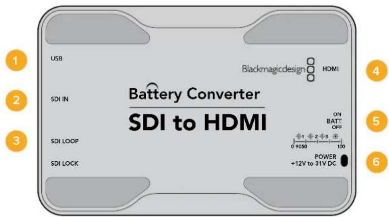
Connectors
1 Mini-B USB port
Connects to the Blackmagic Converters Setup software via your Mac OS X or Windows computer. The Mini Converter's internal software is also updated using the USB port.
2 SDI In
Primary SDI input BNC connector.
3 SDI Loop
Loop through output of your SDI input BNC connector.
4 HDMI
HDMI type A video output.
5 ON BATT OFF
Switches battery power On or Off. When set to On, the Battery Converter will keep working even if external power is lost. When set to Off, only external power is used to ensure built in battery power is saved. The LED near the switch indicates the battery charge level by a continuous illumination for 100 percent charge, three flashes for 50 to 90 percent charge, two flashes for 10 to 50 percent charge and a single flash if less than 10 percent charge is remaining.
6 Power +12V
12 volt power supply input.
Battery Converter SDI to HDMI Block Diagram
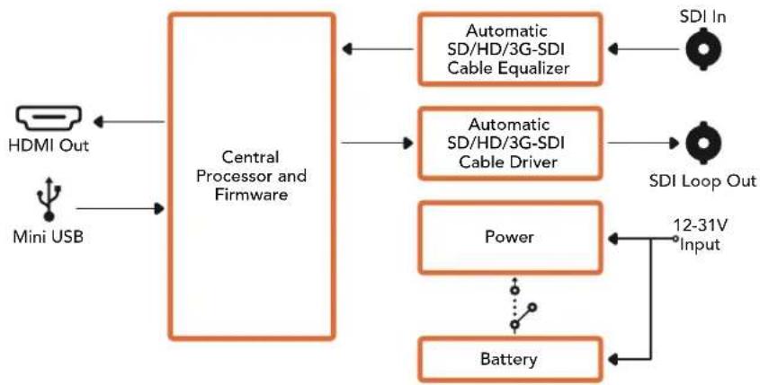
flowchart
graph LR
    A["HDMI Out"] --> B["Central Processor and Firmware"]
    C["Mini USB"] --> B
    B --> D["Automatic SD/HD/3G-SDI Cable Equalizer"]
    B --> E["Automatic SD/HD/3G-SDI Cable Driver"]
    B --> F["Power"]
    B --> G["Battery"]
    D --> H["SDI In"]
    E --> I["SDI Loop Out"]
    F --> J["12-31V Input"]
    G --> K["Battery"]
Battery Converter HDMI to SDI
Your Battery Converter HDMI to SDI can convert HDMI outputs from devices such as HDV cameras and game consoles to SDI. This means you can send video signals from HDMI over SDI using the longest SDI cables. You can even add SDI outputs to computers with HDMI compatibility. Battery Converter HDMI to SDI includes a built in rechargeable battery. Connectors are recessed and protected by an aircraft grade aluminum chassis.
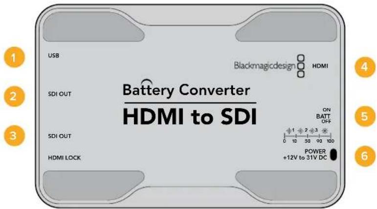
Connectors
1 Mini-B USB port Connects to the Blackmagic Converters Setup software via your Mac OS X or Windows computer. The Mini Converter's internal software is also updated using the USB port.
2 SDI OUT SDI video output BNC connector.
3 SDI OUT Second SDI output.
4 HDMI HDMI type A video input.
5 ON BATT OFF
Switches battery power On or Off. When set to On, the Battery Converter will keep working even if external power is lost. When set to Off, only external power is used to ensure built in battery power is saved. The LED near the switch indicates the battery charge level by a continuous illumination for 100 percent charge, three flashes for 50 to 90 percent charge, two flashes for 10 to 50 percent charge and a single flash if less than 10 percent charge is remaining.
6 Power +12V
12 volt power supply input.
Battery Converter HDMI to SDI Block Diagram
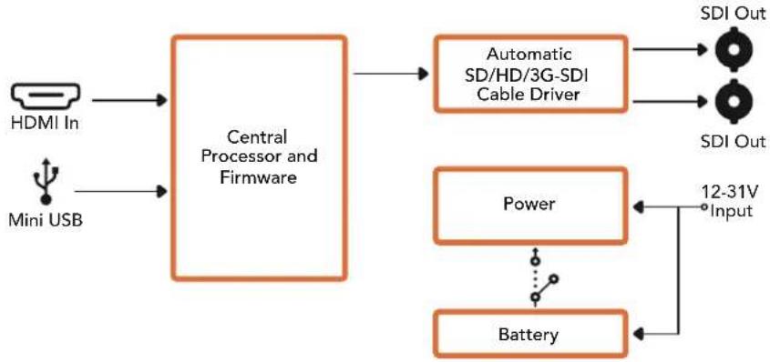
flowchart
graph LR
    A["HDMI In"] --> B["Central Processor and Firmware"]
    C["Mini USB"] --> B
    B --> D["Automatic SD/HD/3G-SDI Cable Driver"]
    D --> E["SDI Out"]
    D --> F["SDI Out"]
    B --> G["Power"]
    G --> H["12-31V Input"]
    G --> I["Battery"]
    I --> H
Help
Getting Help
The fastest way to obtain help is to go to the Blackmagic Design online support pages and check the latest support material available for your Blackmagic Converter.
Blackmagic Design Online Support Pages
The latest manual, software and support notes can be found at the Blackmagic Design support center at www.blackmagicdesign.com/support.
Blackmagic Design Forum
The Blackmagic Design forum on our website is a helpful resource you can visit for more information and creative ideas. This can also be a faster way of getting help as there may already be answers you can find from other experienced users and Blackmagic Design staff which will keep you moving forward. You can visit the forum at https://forum.blackmagicdesign.com
Contacting Blackmagic Design Support
If you can't find the help you need in our support material, or on the forum, please click the "Send us an email" button on the support page to email a support request. Alternatively, click on the "Find your local support team" button and call your nearest Blackmagic Design support office.
Checking the Software Version Currently Installed
To check which version of Converter Setup software is installed on your computer, open the About Blackmagic Converter Setup window.
- On Mac OS X, open Blackmagic Converter Setup from the Applications folder. Select About Blackmagic Converter Setup from the application menu to reveal the version number.
- On Windows, open Blackmagic Converter Setup from your Start menu. Click on the Help menu and select About Blackmagic Converter Setup to reveal the version number.
- On Windows 8, open Blackmagic Converter Setup from the Blackmagic Converter Setup tile on your Start page. Click on the Help menu and select About Blackmagic Converter Setup to reveal the version number.
How to Get the Latest Software Updates
After checking the version of Blackmagic Converters Setup software installed on your computer, please visit
the Blackmagic Design support center at www.blackmagicdesign.com/support to check for the latest updates. While it is usually a good idea to run the latest updates, it is wise to avoid updating any software if you are in the middle of an important project.
Warranty
Limited Warranty
Blackmagic Design warrants that Mini Converters and Mini Converters Heavy Duty will be free from defects in materials and workmanship for a period of 36 months from the date of purchase excluding connectors, cables, fiber optic modules, fuses and batteries which will be free from defects in materials and workmanship for a period of 12 months from the date of purchase. Blackmagic Design warrants that Battery Converters will be free from defects in materials and workmanship for a period of 12 months from the date of purchase. If a product proves to be defective during this warranty period, Blackmagic Design, at its option, either will repair the defective product without charge for parts and labor, or will provide a replacement in exchange for the defective product.
In order to obtain service under this warranty, you the Customer, must notify Blackmagic Design of the defect before the expiration of the warranty period and make suitable arrangements for the performance of service. The Customer shall be responsible for packaging and shipping the defective product to a designated service center nominated by Blackmagic Design, with shipping charges pre paid. Customer shall be responsible for paying all shipping charges, insurance, duties, taxes, and any other charges for products returned to us for any reason.
This warranty shall not apply to any defect, failure or damage caused by improper use or improper or inadequate maintenance and care. Blackmagic Design shall not be obligated to furnish service under this warranty: a) to repair damage resulting from attempts by personnel other than Blackmagic Design representatives to install, repair or service the product, b) to repair damage resulting from improper use or connection to incompatible equipment, c) to repair any damage or malfunction caused by the use of non Blackmagic Design parts or supplies, or d) to service a product that has been modified or integrated with other products when the effect of such a modification or integration increases the time or difficulty of servicing the product. THIS WARRANTY IS GIVEN BY BLACKMAGIC DESIGN IN LIEU OF ANY OTHER WARRANTIES, EXPRESS OR IMPLIED. BLACKMAGIC DESIGN AND ITS VENDORS DISCLAIM ANY IMPLIED WARRANTIES OF MERCHANTABILITY OR FITNESS FOR A PARTICULAR PURPOSE. BLACKMAGIC DESIGN'S RESPONSIBILITY TO REPAIR OR REPLACE DEFECTIVE PRODUCTS IS THE WHOLE AND EXCLUSIVE REMEDY PROVIDED TO THE CUSTOMER FOR ANY INDIRECT, SPECIAL, INCIDENTAL OR CONSEQUENTIAL DAMAGES IRRESPECTIVE OF WHETHER BLACKMAGIC DESIGN OR THE VENDOR HAS ADVANCE NOTICE OF THE POSSIBILITY OF SUCH DAMAGES. BLACKMAGIC DESIGN IS NOT LIABLE FOR ANY ILLEGAL USE OF EQUIPMENT BY CUSTOMER. BLACKMAGIC IS NOT LIABLE FOR ANY DAMAGES RESULTING FROM USE OF THIS PRODUCT. USER OPERATES THIS PRODUCT AT OWN RISK.
Copyright 2018 Blackmagic Design. All rights reserved. 'Blackmagic Design', 'DeckLink', 'HDLink', 'Workgroup Videohub', 'Multibridge Pro', 'Multibridge Extreme', 'Intensity' and 'Leading the creative video revolution' are registered trademarks in the US and other countries. All other company and product names may be trade marks of their respective companies with which they are associated.

natural_image
Circular portrait photo of a smiling man in a black shirt against a gray background (no text or symbols)ようこそ
Blackmagic Design CEO
グラント・ペティ
目次
Blackmagic Converters
はじめに 95
電源の接続 95
ビデオの接続 96
オー ディオの接続 97
管理ソフトウェアの インストール 98
Blackmagic Converters Setupの
インストール 98
内部ソフトウェアのアップデート 99
Mini Converter SDI Distribution
4Kのアップデート 100
設定の変更 101
スイッチを使用して設定を変更 101
Blackmagic Converters Setupを
使用して設定を変更 102
Aboutタブ 103
Battery Converter SDI to HDMI 177
Battery Converter HDMI to SDI 178
ヘルプ 180
保証 181
はじめに
natural_image
Illustration of a rectangular electronic device with internal components and a metallic connector (no visible text or symbols)natural_image
Technical line drawing of a mechanical component with multiple ports and internal channels (no text or symbols)natural_image
3D technical diagram of an electronic device casing with multiple ports and orange connectors (no text or symbols)natural_image
Technical illustration of a computer hardware component with slots and connectors (no text or symbols)natural_image
Illustration of a hand inserting an orange USB into a computer motherboard (no text or symbols visible)flowchart
graph TD
    A["SDI In"] --> B["Input automatically detects between SD, HD and 3G-SDI"]
    C["Alt SDI In"] --> D["Central Processor and Firmware"]
    E["USB"] --> D
    B --> F["Redundant Input Automatic Change Over"]
    D --> G["Equalizer, Re-Clocker and 10 bit De-Serializer"]
    F --> H["SDI Audio De-Embedder"]
    G --> I["Customizable Video Processor"]
    H --> J["AES/EBU Audio Formatter"]
    I --> K["Audio Digital to Analog with Balanced Output"]
    J --> L["Automatic SD/HD/3G-SDI Cable Driver"]
    K --> M["Handheld via Analog or AES/EBU Audio Out Switch"]
    L --> N["Loop SDI Out"]
    M --> O["Left Analog Out or AES/EBU Out"]
    N --> P["Right Analog Out"]
    Q["Mini Switches"] --> D
    R["D HDMI Out"] --> S["Output Device"]
Mini Converter SDI to HDMI 4K
flowchart
graph TD
    A["SDI In"] --> B["Redundant Input Automatic Change Over"]
    C["Alt SDI In"] --> D["Central Processor and Firmware"]
    E["USB"] --> D
    B --> F["Equalizer, Re-Clocker and 10 bit De-Serializer"]
    D --> G["Video Processor and Down Converter"]
    F --> H["SDI Audio De-Embedder"]
    G --> H
    H --> I["AES/EBU Audio Formatter"]
    H --> J["Audio Digital to Analog with Balanced Output"]
    H --> K["HDMI Video and Audio Formatter and Instant Lock"]
    I --> L["Automatic SD/HD/Ultra HD Cable Driver"]
    J --> L
    K --> M["Loop SDI Out"]
    L --> N["Analog or AES/EBU Audio Out Switch"]
    M --> O["Left Analog Out or AES/EBU Out"]
    N --> P["Right Analog Out"]
    O --> Q["HDMI Out"]
    P --> Q
    Q --> R["Mini Switches"]
Mini Converter SDI to HDMI 6G
flowchart
graph TD
    A["SDI In"] --> B["Input automatically detects between SD, HD and Ultra HD"]
    C["Alt SDI In"] --> D["Central Processor and Firmware"]
    E["USB"] --> D
    B --> F["Redundant Input Automatic Change Over"]
    D --> F
    F --> G["Equalizer, Re-Clocker and 10 bit De-Serializer"]
    G --> H["Video Processor and Down Converter"]
    H --> I["SDI Audio De-Embedder"]
    I --> J["AES/EBU Audio Formatter"]
    I --> K["Audio Digital to Analog with Balanced Output"]
    J --> L["Automatic SD/HD/Ultra HD Cable Driver"]
    K --> L
    L --> M["Loop SDI Out"]
    L --> N["Analog or AES/EBU Audio Out Switch"]
    N --> O["Left Analog Out or AES/EBU Out"]
    N --> P["Right Analog Out"]
    I --> Q["HDMI Video and Audio Formatter and Instant Lock"]
    Q --> R["HDMI Out"]
    D --> S["Mini Switches"]
Mini Converter HDMI to SDI
Mini Converter SDI to Analog
flowchart
graph TD
    A["SDI In"] --> B["Input automatically detects between SD, HD and 1.5G-SDI"]
    C["Alt SDI In"] --> D["Central Processor and Firmware"]
    E["USB"] --> D
    B --> F["Redundant Input Automatic Change Over"]
    D --> F
    F --> G["Equalizer, Re-Clocker and 10 bit De-Serializer"]
    G --> H["10 bit HD to SD Down Converter"]
    H --> I["SDI Audio De-Embedder"]
    I --> J["AES/EBU Audio Formatter"]
    I --> K["Audio Digital to Analog with Balanced Output"]
    I --> L["12 Bit Digital to Analog SD/HD Video Converter"]
    J --> M["Automatic SD/HD/1.5G-SDI Cable Driver"]
    K --> N["Analog or AES/EBU Audio Out Switch"]
    L --> O["Component output can switch to S-Video and composite"]
    M --> P["Loop SDI Out"]
    N --> Q["Left Analog Out or AES/EBU Out"]
    O --> R["Y"]
    O --> S["R-Y"]
    O --> T["B-Y"]
Mini Converter SDI to Analog 4K
other
MiniConverter SDI to Analog 4K | Category | OFF | ON | |---|---|---| | ANALOG AUDIO | AES/EBU AUDIO | | | 7.5 IRE | 0.0 IRE | | | SMPTE LEVELS | BETACAM LEVELS | | | COMPONENT | COMPOSITE S-VIDEO | | | SDI AUDIO DE-EMBED BIT 2 | | | | SDI AUDIO DE-EMBED BIT 1 | | | | SDI AUDIO DE-EMBED BIT 0 | | | | PROCESSING OFF | PROCESSING ON | Toggle processing switch to step through down converter mode (□=2) |flowchart
graph TD
    A["SDI In"] --> B["Input automatically detects between SD, HD and Ultra HD"]
    C["Alt SDI In"] --> D["Central Processor and Firmware"]
    E["USB"] --> D
    B --> F["Redundant Input Automatic Change Over"]
    D --> G["Equalizer, Re-Clocker and 10 bit De-Serializer"]
    G --> H["10 bit HD to 5D Down Converter"]
    H --> I["SDI Audio De-Embedder"]
    I --> J["AES/EBU Audio Formatter"]
    I --> K["Audio Digital to Analog with Balanced Output"]
    I --> L["12 Bit Digital to Analog SD/HD Video Converter"]
    J --> M["Automatic SD/HD/Ultra HD Cable Driver"]
    K --> N["Analog or AES/EBU Audio Out Switch"]
    L --> O["Component output can switch to S-Video and composite"]
    M --> P["Loop SDI Out"]
    N --> Q["Left Analog Out or AES/EBU Out"]
    O --> R["Y"]
    O --> S["R-Y"]
    O --> T["B-Y"]
Mini Converter Analog to SDI
Mini Converter SDI to Audio
Mini Converter Audio to SDI
flowchart
graph TD
    A["USB"] --> B["Central Processor and Firmware"]
    C["SDI In"] --> D["Automatic SD/HD/Ultra HD Equalizer"]
    E["SDI Out"] --> F["Automatic SD/HD/Ultra HD Cable Driver"]
    D --> G["Reclocker"]
    F --> H["Reclocker"]
    G --> I["1310nm Laser Driver with LC Connector"]
    H --> J["1310nm Laser Receiver with LC Connector"]
    I --> K["Optical Out"]
    J --> L["Optical In"]
    style G stroke-dasharray: 5 5
    style H stroke-dasharray: 5 5
    style I stroke-dasharray: 5 5
    style J stroke-dasharray: 5 5
    style K stroke-dasharray: 5 5
    style L stroke-dasharray: 5 5
Mini Converter Optical Fiber 12G
flowchart
graph LR
    A["SDI In 1"] --> D["SDI Multiplex"]
    B["SDI In 2"] --> D
    C["SDI In 3"] --> D
    E["SDI In 4"] --> D
    F["USB"] --> G["Central Processor and Firmware"]
    D --> H["Equalizer, Re-Clocker and 10 bit De-Serializer"]
    H --> I["Customizable Video Processor"]
    I --> J["HDMI Video and Audio Formatter"]
    J --> K["HDMI Out"]
    D -.-> L["SD/HD/6G-SDI"]
Mini Converter SDI Distribution
接続
1-8 SDI出力 (SDI OUT)
SDIビデオ出力用のBNCコネクター。
9 SDI入力 (SDI IN)
SDI入力。
接続
1-8 SDI出力 (SDI OUT)
SDIビデオ出力用のBNCコネクター。
9 SDI入力 (SDI IN)
SDI入力。
flowchart
graph LR
    A["SDI IN 1"] --> B["Cable EQ"]
    C["SDI IN 2"] --> D["Cable EQ"]
    E["SDI IN 3"] --> F["Cable EQ"]
    G["SDI IN 4"] --> H["Cable EQ"]
    B --> I["Central Processor and Firmware"]
    D --> I
    F --> I
    H --> I
    I --> J["Cable Driver"]
    I --> K["Cable Driver"]
    I --> L["Cable Driver"]
    I --> M["Cable Driver"]
    J --> N["SDI OUT 1"]
    K --> O["SDI OUT 2"]
    L --> P["SDI OUT 3"]
    M --> Q["SDI OUT 4"]
    I --> R["USB"]
Mini Converter Sync Generator
Battery Converter SDI to HDMI
Battery Converter HDMI to SDI
natural_image
Circular portrait photo of a smiling man in a dark shirt against a gray background (no text or symbols)Bienvenue
natural_image
Front view of a beige electronic device with ports and an internal connector (no visible text or symbols)natural_image
Illustration of a beige electronic device with internal components and a labeled part (no readable text or symbols beyond branding)natural_image
Technical line drawing of a mechanical connector or housing assembly (no text or symbols)natural_image
3D technical diagram of an electronic device casing with multiple ports and orange connectors (no text or symbols)natural_image
Illustration of a hand holding a mechanical component with multiple slots and connectors (no text or symbols visible)natural_image
Illustration of a hand inserting an orange USB into a computer motherboard (no text or symbols visible)flowchart
graph TD
    A["SDI In"] --> B["Input automatically detects between SD, HD and Ultra HD"]
    C["Alt SDI In"] --> D["Central Processor and Firmware"]
    E["USB"] --> D
    B --> F["Redundant Input Automatic Change Over"]
    D --> G["SDI Audio De-Embedder"]
    F --> H["Equalizer, Re-Clocker and 10 bit De-Serializer"]
    G --> I["Video Processor and Down Converter"]
    H --> J["AES/EBU Audio Formatter"]
    I --> K["Audio Digital to Analog with Balanced Output"]
    J --> L["Automatic SD/HD/Ultra HD Cable Driver"]
    K --> M["Handheld via AES/EBU Audio Out Switch"]
    L --> N["Loop SDI Out"]
    M --> O["Left Analog Out or AES/EBU Out"]
    N --> P["Right Analog Out"]
    Q["Mini Switches"] --> D
    R["HDMI Video and Audio Formatter and Instant Lock"] --> G
Mini Converter SDI to HDMI 6G
| Audio Channels Switch 4 Switch 3 Switch 2 Switch Diagram | ||
| 1 and 2 OFF OFF OFF | 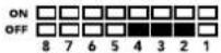 | |
| 3 and 4 OFF OFF ON | 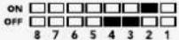 | |
| 5 and 6 OFF ON OFF | 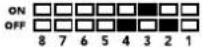 | |
| 7 and 8 OFF ON ON | 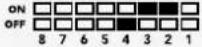 | |
| 9 and 10 ON OFF OFF | 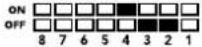 | |
| 11 and 12 ON OFF ON | 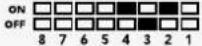 | |
| 13 and 14 ON ON OFF | 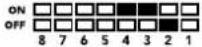 | |
| 15 and 16 ON ON ON | 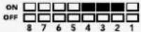 | |
- Clip Video Output to Legal Levels
flowchart
graph TD
    A["Left Analog In or AES/EBU"] --> B["Analog or AES/EBU Audio Switch"]
    C["Right Analog In"] --> D["HDMI In"]
    E["USB"] --> F["Central Processor and Firmware"]
    B --> G["AES/EBU Sample Rate Converter"]
    D --> H["HDMI Video and Audio Decoder"]
    F --> I["Customizable Video Processor"]
    G --> J["SDI Audio Embedder"]
    H --> J
    I --> J
    J --> K["Automatic SD/HD/3G-SDI Cable Driver"]
    K --> L["SDI Out"]
    G --> M["Audio Analog to Digital with Balanced Input"]
    H --> N["Mini Switches"]
    I --> O["DSI Out"]
Mini Converter HDMI to SDI 4K
Mini Converter SDI to Analog
flowchart
graph TD
    A["SDI In"] --> B["Input automatically detects between SD, HD and 1.5G-SDI"]
    C["Alt SDI In"] --> D["Central Processor and Firmware"]
    E["USB"] --> D
    B --> F["Redundant Input Automatic Change Over"]
    D --> G["Equalizer, Re-Clocker and 10 bit De-Serializer"]
    F --> H["10 bit HD to SD Down Converter"]
    G --> H
    H --> I["SDI Audio De-Embedder"]
    I --> J["AES/EBU Audio Formatter"]
    I --> K["Audio Digital to Analog with Balanced Output"]
    I --> L["12 Bit Digital to Analog SD/HD Video Converter"]
    J --> M["Automatic SD/HD/1.5G-SDI Cable Driver"]
    K --> N["Analog or AES/EBU Audio Out Switch"]
    L --> O["Component output can switch to S-Video and composite"]
    M --> P["Loop SDI Out"]
    N --> Q["Left Analog Out or AES/EBU Out"]
    O --> R["Y"]
    O --> S["R-Y"]
    O --> T["B-Y"]
Mini Converter SDI to Analog 4K
flowchart
graph TD
    A["SDI In"] --> B["Input automatically detects between SD, HD and Ultra HD"]
    C["Alt SDI In"] --> D["Central Processor and Firmware"]
    E["USB"] --> D
    B --> F["Redundant Input Automatic Change Over"]
    D --> G["Equalizer, Re-Clocker and 10 bit De-Serializer"]
    D --> H["10 bit HD to SD Down Converter"]
    D --> I["SDI Audio De-Embedder"]
    F --> J["AES/EBU Audio Formatter"]
    G --> K["Audio Digital to Analog with Balanced Output"]
    H --> L["12 Bit Digital to Analog SD/HD Video Converter"]
    I --> L
    J --> M["Automatic SD/HD/Ultra HD Cable Driver"]
    K --> M
    L --> N["Loop SDI Out"]
    M --> O["Analog or AES/EBU Audio Out Switch"]
    N --> P["Left Analog Out or AES/EBU Out"]
    O --> Q["Right Analog Out"]
    P --> R["Y"]
    P --> S["R-Y"]
    P --> T["B-Y"]
    U["Component output can switch to S-Video and composite"] --> L
    U --> M
    U --> N
    U --> P
Mini Converter Analog to SDI
Mini Converter SDI to Audio
flowchart
graph TD
    A["SDI In"] --> B["Input automatically detects between SD, HD and 3G-SDI"]
    C["Alt SDI In"] --> D["Central Processor and Firmware"]
    E["USB"] --> D
    B --> F["Redundant Input Automatic Change Over"]
    D --> F
    F --> G["Equalizer, Re-Clocker and 10 bit De-Serializer"]
    G --> H["SDI Audio De-Embedder"]
    H --> I["AES/EBU Audio Formatter"]
    H --> J["Audio Digital to Analog with Balanced Output"]
    H --> K["AES/EBU Audio Formatter"]
    I --> L["Automatic SD/HD/3G-SDI Cable Driver"]
    J --> L
    K --> L
    L --> M["Loop SDI Out"]
    I --> N["Ch 1 Analog or Ch 1&2 AES/EBU"]
    J --> O["Ch 2 Analog or Ch 3&4 AES/EBU"]
    K --> P["Ch 3 Analog or Ch 5&6 AES/EBU"]
    L --> Q["Ch 4 Analog or Ch 7&8 AES/EBU"]
    M --> R["Output"]
    N --> R
    O --> R
    P --> R
    Q --> R
Mini Converter SDI to Audio 4K
Mini Converter Audio to SDI
flowchart
graph TD
    A["USB"] --> B["Central Processor and Firmware"]
    B --> C["Reclocker"]
    C --> D["1310nm Laser Driver with LC Connector"]
    D --> E["Optical Out"]
    F["SDI In"] --> G["Automatic SD/HD/Ultra HD Equalizer"]
    G --> H["Reclocker"]
    I["SDI Out"] --> J["Automatic SD/HD/Ultra HD Cable Driver"]
    J --> K["Reclocker"]
    K --> L["1310nm Laser Receiver with LC Connector"]
    L --> M["Optical In"]
    N["SFP Optical Fiber Transmitter and Receiver Module"] -.-> L
Mini Converter Optical Fiber 12G
flowchart
graph LR
    A["SDI In"] --> B["Automatic SD/HD/12G-SDI Equalizer"]
    B --> C["Re-Clocker"]
    C --> D["1310nm Laser Driver with LC Connector"]
    D --> E["Optical Out"]
    F["SDI Out"] --> G["Automatic SD/HD/12G-SDI Driver"]
    G --> H["Re-Clocker"]
    H --> I["1310nm Laser Receiver with LC Connector"]
    I --> J["Optical In"]
    C -.-> K["SFP Optical Fiber Transmitter and Receiver Module"]
    I -.-> K
Mini Converter Quad SDI to HDMI 4K
Connecteurs
1-8 Sorties SDI
Connecteurs
1-8 Sorties SDI
flowchart
graph LR
    A["SDI IN 1"] --> B["Cable EQ"]
    C["SDI IN 2"] --> D["Cable EQ"]
    E["SDI IN 3"] --> F["Cable EQ"]
    G["SDI IN 4"] --> H["Cable EQ"]
    B --> I["Central Processor and Firmware"]
    D --> I
    F --> I
    H --> I
    I --> J["Cable Driver"]
    J --> K["SDI OUT 1"]
    I --> L["Cable Driver"]
    L --> M["SDI OUT 2"]
    I --> N["Cable Driver"]
    N --> O["SDI OUT 3"]
    I --> P["Cable Driver"]
    P --> Q["SDI OUT 4"]
    U["USB"] --> I
Mini Converter Sync Generator
natural_image
Diagram showing a circle inscribed in a square with an arrow indicating transformation (no text or symbols)16:9 Ratio Display4:3 Ratio Image
Battery Converter SDI to HDMI
Battery Converter HDMI to SDI
natural_image
Circular portrait photo of a smiling man in a dark shirt against a gray background (no text or symbols)Willkommen
CEO, Blackmagic Design
Inhaltsverzeichnis
Blackmagic Converters
Erste Schritte 275
Battery Converter HDMI to SDI 358
Hilfe 360
Garantie 361
Erste Schritte
natural_image
Illustration of a beige electronic device with internal components and no visible text or symbolsnatural_image
Technical line drawing of a mechanical connector or connector assembly (no text or symbols)natural_image
3D technical diagram of an electronic device casing with multiple ports and mounting holes (no text or symbols)natural_image
Technical illustration of a mechanical assembly with multiple slots and a central slot, being handled by hands (no text or symbols present)natural_image
Illustration of a hand inserting an orange USB into a computer motherboard (no text or symbols visible)2 L - ANALOG or AES/EBU
Switch 8 - ANALOG AUDIO, AES/EBU AUDIO
Switch 1 – PROCESSING OFF, PROCESSING ON
flowchart
graph TD
    A["SDI In"] --> B["Input automatically detects between SD, HD and 3G-SDI"]
    C["Alt SDI In"] --> D["Central Processor and Firmware"]
    E["USB"] --> D
    B --> F["Redundant Input Automatic Change Over"]
    D --> G["SDI Audio De-Embedder"]
    F --> H["Equalizer, Re-Clocker and 10 bit De-Serializer"]
    G --> I["Customizable Video Processor"]
    H --> J["AES/EBU Audio Formatter"]
    I --> K["Audio Digital to Analog with Balanced Output"]
    J --> L["Automatic SD/HD/3G-SDI Cable Driver"]
    K --> M["Long SDI Out"]
    L --> N["Loop SDI Out"]
    M --> O["Left Analog Out or AES/EBU Out"]
    N --> P["Right Analog Out"]
    Q["Mini Switches"] --> D
    R["HDMI Out"] --> S["HDMI Video and Audio Formatter"]
Mini Converter SDI to HDMI 4K
2 L - ANALOG or AES/EBU
Switch 8 - ANALOG AUDIO, AES/EBU AUDIO
Switch 1 – PROCESSING OFF, PROCESSING ON
flowchart
graph TD
    A["SDI In"] --> B["Redundant Input Automatic Change Over"]
    C["Alt SDI In"] --> D["Central Processor and Firmware"]
    E["USB"] --> D
    B --> F["Equalizer, Re-Clocker and 10 bit De-Serializer"]
    D --> G["Video Processor and Down Converter"]
    F --> H["SDI Audio De-Embedder"]
    G --> I["HDMI Audio and Audio Formatter and Instant Lock"]
    H --> J["AES/EBU Audio Formatter"]
    I --> K["Audio Digital to Analog with Balanced Output"]
    J --> L["Automatic SD/HD/Ultra HD Cable Driver"]
    K --> M["Loop SDI Out"]
    L --> N["Analog or AES/EBU Audio Out Switch"]
    M --> O["Left Analog Out or AES/EBU Out"]
    N --> P["Right Analog Out"]
    Q["Mini Switches"] --> D
Mini Converter SDI to HDMI 6G
2 L - ANALOG or AES/EBU
Switch 8 - ANALOG AUDIO, AES/EBU AUDIO
Switch 7 - LUT OFF, LUT ON
Switch 5 – LUT ON LOOP OFF, LUT ON LOOP ON
2 L - ANALOG or AES/EBU
Switch 8 - ANALOG AUDIO, AES/EBU AUDIO
Switch 1 – PROCESSING OFF, PROCESSING ON
2 L - ANALOG or AES/EBU
Switch 8 - ANALOG AUDIO, AES/EBU AUDIO
Switches 2, 1 – SELECT FORMAT BIT 1,0
2 L - ANALOG or AES/EBU
Switch 8 – ANALOG AUDIO, AES/EBU AUDIO
Switches 2, 1 – SELECT FORMAT BIT 1,0
Mini Converter SDI to Analog
4 L - ANALOG or AES/EBU
Switch 8 - ANALOG AUDIO, AES/EBU AUDIO
Switch 7 - 7.5 IRE, 0.0 IRE
Switch 1 – PROCESSING OFF, PROCESSING ON
4 L - ANALOG or AES/EBU
Switch 8 - ANALOG AUDIO, AES/EBU AUDIO
Switch 7 - 7.5 IRE, 0.0 IRE
Switch 1 – PROCESSING OFF, PROCESSING ON
flowchart
graph TD
    A["Input automatically detects between SD, HD and Ultra HD"] --> B["Redundant Input Automatic Change Over"]
    C["Alt SDI In"] --> D["Central Processor and Firmware"]
    E["USB"] --> D
    B --> F["Equalizer, Re-Clocker and 10 bit De-Serializer"]
    D --> G["SDI Audio De-Embedder"]
    F --> H["10 bit HD to SD Down Converter"]
    G --> I["12 Bit Digital to Analog SD/HD Video Converter"]
    H --> J["AES/EBU Audio Formatter"]
    I --> K["Audio Digital to Analog with Balanced Output"]
    J --> L["Automatic SD/HD/Ultra HD Cable Driver"]
    K --> M["Long SDI Out"]
    L --> N["Analog or AES/EBU Audio Out Switch"]
    M --> O["Left Analog Out or AES/EBU Out"]
    N --> P["Right Analog Out"]
    Q["Component output can switch to S-Video and composite"] --> R["Y"]
    Q --> S["R-Y"]
    Q --> T["B-Y"]
    U["Mini Switches"] --> D
Mini Converter Analog to SDI
4 L - ANALOG or AES/EBU
Switch 8 - ANALOG AUDIO, AES/EBU AUDIO
Switch 7 - 7.5 IRE, 0.0 IRE
Switch 1 - PROCESSING OFF, PROCESSING ON
Mini Converter SDI to Audio
1 CH 1 ANALOG or CH 1 & 2 AES/EBU
Switch 8 - ANALOG AUDIO, AES/EBU AUDIO
flowchart
graph TD
    A["SDI In"] --> B["Input automatically detects between SD, HD and 3G-SDI"]
    C["Alt SDI In"] --> D["Central Processor and Firmware"]
    E["USB"] --> D
    B --> F["Redundant Input Automatic Change Over"]
    D --> F
    F --> G["Equalizer, Re-Clocker and 10 bit De-Serializer"]
    G --> H["SDI Audio De-Embedder"]
    H --> I["AES/EBU Audio Formatter"]
    H --> J["Audio Digital to Analog with Balanced Output"]
    H --> K["AES/EBU Audio Formatter"]
    I --> L["Automatic SD/HD/3G-SDI Cable Driver"]
    J --> L
    K --> L
    L --> M["Loop SDI Out"]
    I --> N["Ch 1 Analog or Ch 1&2 AES/EBU"]
    J --> O["Ch 2 Analog or Ch 3&4 AES/EBU"]
    K --> P["Ch 3 Analog or Ch 5&6 AES/EBU"]
    L --> Q["Ch 4 Analog or Ch 7&8 AES/EBU"]
    M --> R["Output"]
    N --> R
    O --> R
    P --> R
    Q --> R
Mini Converter SDI to Audio 4K
1 CH 1 ANALOG or CH 1 & 2 AES/EBU
Switch 8 - ANALOG AUDIO, AES/EBU AUDIO
flowchart
graph TD
    A["SDI In"] --> B["Redundant Input Automatic Change Over"]
    C["Alt SDI In"] --> D["Central Processor and Firmware"]
    E["USB"] --> D
    B --> F["Equalizer, Re-Clocker and 10 bit De-Serializer"]
    D --> F
    F --> G["SDI Audio De-Embedder"]
    G --> H["AES/EBU Audio Formatter"]
    G --> I["Audio Digital to Analog with Balanced Output"]
    G --> J["AES/EBU Audio Formatter"]
    H --> K["Automatic SD/HD/Ultra HD Cable Driver"]
    I --> K
    J --> K
    K --> L["Loop SDI Out"]

    M["Mini Switches"] --> D
    N["Input automatically detects between SD, HD and Ultra HD"] --> B
    O["Input automatically detects between SD, HD and Ultra HD"] --> C
Mini Converter Audio to SDI
Switch 8 - ANALOG AUDIO, AES/EBU AUDIO
Switch 8 - ANALOG AUDIO, AES/EBU AUDIO
flowchart
graph LR
    A["SDI In 1"] --> D["SDI Multiplex"]
    B["SDI In 2"] --> D
    C["SDI In 3"] --> D
    E["SDI In 4"] --> D
    F["USB"] --> G["Central Processor and Firmware"]
    D --> H["Equalizer, Re-Clocker and 10 bit De-Serializer"]
    H --> I["Customizable Video Processor"]
    I --> J["HDMI Video and Audio Formatter"]
    J --> K["HDMI Out"]
    D -.-> L["SD/HD/6G-SDI"]
    G -.-> L
Mini Converter SDI Distribution
Anschlüsse

3 SDI OUT
Anschlüsse
1-8 SDI OUT
Switch 1 – PROCESSING ON/OFF
flowchart
graph LR
    A["SDI IN 1"] --> B["Cable EQ"]
    C["SDI IN 2"] --> D["Cable EQ"]
    E["SDI IN 3"] --> F["Cable EQ"]
    G["SDI IN 4"] --> H["Cable EQ"]
    B --> I["Central Processor and Firmware"]
    D --> I
    F --> I
    H --> I
    I --> J["Cable Driver"]
    I --> K["Cable Driver"]
    I --> L["Cable Driver"]
    I --> M["Cable Driver"]
    J --> N["SDI OUT 1"]
    K --> O["SDI OUT 2"]
    L --> P["SDI OUT 3"]
    M --> Q["SDI OUT 4"]
    R["USB"] --> I
Mini Converter Sync Generator
Switch 1 – PROCESSING OFF, PROCESSING ON
Switch 1 – PROCESSING OFF, PROCESSING ON
natural_image
Diagram showing a circle being converted into a square, with no text or symbols present.16:9 Ratio Display4:3 Ratio Image
Battery Converter SDI to HDMI
Battery Converter HDMI to SDI
natural_image
Circular portrait photo of a smiling man in a dark shirt against a gray background (no text or symbols)Bienvenido
natural_image
Front view of a beige electronic device labeled 'Vcc/1000000000000000000000000000000000000000000000000000000000000000000000000' with no visible text or symbols on the body.natural_image
Illustration of a rectangular electronic device with internal components and labeled ports (no readable text or symbols)natural_image
Technical line drawing of a mechanical component with no visible text or symbolsConexiones de audio
natural_image
3D technical diagram of an electronic device casing with multiple ports and mounting holes (no text or symbols)natural_image
Technical illustration of a mechanical component with multiple slots and mounting holes, held by hands (no text or symbols)natural_image
Illustration of a hand holding an orange USB connector next to a computer motherboard (no text or symbols visible)Conectores
1 HDMI OUT
Salida HDMI tipo A.
2 HDMI IN
2 L - ANALOG or AES/EBU
Interruptor 3 - Aislar audio SDI, bit 1
Interruptor 2 - Aislar audio SDI, bit 0
flowchart
graph TD
    A["Input automatically detects between SD, HD and 3G-SDI"] --> B["Redundant Input Automatic Change Over"]
    C["Alt SDI In"] --> D["Central Processor and Firmware"]
    E["USB"] --> D
    B --> F["Equalizer, Re-Clocker and 10 bit De-Serializer"]
    D --> G["SDI Audio De-Embedder"]
    F --> H["Customizable Video Processor"]
    G --> I["HDMI Video and Audio Formatter"]
    H --> J["AES/EBU Audio Formatter"]
    I --> K["Audio Digital to Analog with Balanced Output"]
    J --> L["Automatic SD/HD/3G-SDI Cable Driver"]
    K --> M["Analog or AES/EBU Audio Out Switch"]
    L --> N["Loop SDI Out"]
    M --> O["Left Analog Out or AES/EBU Out"]
    N --> P["Right Analog Out"]
    Q["Mini Switches"] --> D
Mini Converter SDI to HDMI 4K
2 L - ANALOG or AES/EBU
Interruptor 4 - Aislar audio SDI, bit 2
Interruptor 2 - Aislar audio SDI, bit 0
flowchart
graph TD
    A["SDI In"] --> B["Input automatically detects between SD, HD and Ultra HD"]
    C["Alt SDI In"] --> D["Central Processor and Firmware"]
    E["USB"] --> D
    B --> F["Redundant Input Automatic Change Over"]
    D --> F
    F --> G["Equalizer, Re-Clocker and 10 bit De-Serializer"]
    G --> H["Video Processor and Down Converter"]
    H --> I["SDI Audio De-Embedder"]
    I --> J["AES/EBU Audio Formatter"]
    I --> K["Audio Digital to Analog with Balanced Output"]
    J --> L["Automatic SD/HD/Ultra HD Cable Driver"]
    K --> L
    L --> M["Loop SDI Out"]
    L --> N["Left Analog Out or AES/EBU Out"]
    L --> O["Right Analog Out"]
    L --> P["HDMI Out"]
    Q["Mini Switches"] --> D
    R["Dual line"] -.-> I
Mini Converter SDI to HDMI 6G
2 L - ANALOG or AES/EBU
Interruptor 8 – Audio analógico, AES/EBU
Interruptor 6 – LUT 1, LUT 2
Interruptor 4 – Aislar audio SDI, bit 2
Interruptor 3 – Aislar audio SDI, bit 1
Interruptor 2 – Aislar audio SDI, bit 0
| Canales de audio | Interruptor 4 | Interruptor 3 | Interruptor 2 | Diagrama |
| 1 and 2 OFF OFF OFF | | |||
| 3 and 4 OFF OFF ON | | |||
| 5 and 6 OFF ON OFF | 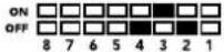 | |||
| 7 and 8 OFF ON ON | 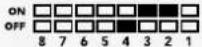 | |||
| 9 and 10 ON OFF OFF | 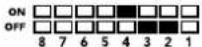 | |||
| 11 and 12 ON OFF ON | 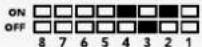 | |||
| 13 and 14 ON ON OFF | 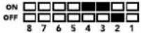 | |||
| 15 and 16 ON ON ON | |
Opciones del programa Blackmagic Converters Setup
2 L - ANALOG or AES/EBU
flowchart
graph TD
    A["Left Analog In or AES/EBU"] --> B["Analog or AES/EBU Audio Switch"]
    C["Right Analog In"] --> D["HDMI In"]
    E["USB"] --> F["Central Processor and Firmware"]
    B --> G["AES/EBU Sample Rate Converter"]
    D --> H["HDMI Video and Audio Decoder"]
    F --> I["Customizable Video Processor"]
    G --> J["SDI Audio Embedder"]
    H --> J
    I --> J
    J --> K["Automatic SD/HD/3G-SDI Cable Driver"]
    K --> L["SDI Out"]
    G --> M["Audio Analog to Digital with Balanced Input"]
    M --> J
    I --> N["Mini Switches"]
Mini Converter HDMI to SDI 4K
2 L - ANALOG or AES/EBU
2 L - ANALOG or AES/EBU
Interruptor 8 – Audio analógico, AES/EBU
Mini Converter SDI to Analog
4 L - ANALOG or AES/EBU
Interruptor 3 - Aislar audio SDI, bit 1
Interruptor 2 - Aislar audio SDI, bit 0
4 L - ANALOG or AES/EBU
flowchart
graph TD
    A["SDI In"] --> B["Input automatically detects between SD, HD and Ultra HD"]
    C["Alt SDI In"] --> D["Central Processor and Firmware"]
    E["USB"] --> D
    B --> F["Redundant Input Automatic Change Over"]
    D --> G["Equalizer, Re-Clocker and 10 bit De-Serializer"]
    G --> H["10 bit HD to SD Down Converter"]
    H --> I["SDI Audio De-Embedder"]
    I --> J["AES/EBU Audio Formatter"]
    I --> K["Audio Digital to Analog with Balanced Output"]
    J --> L["Automatic SD/HD/Ultra HD Cable Driver"]
    K --> M["12 Bit Digital to Analog SD/HD Video Converter"]
    L --> N["Loop SDI Out"]
    M --> O["Analog or AES/EBU Audio Out Switch"]
    M --> P["Left Analog Out or AES/EBU Out"]
    M --> Q["Right Analog Out"]
    Q --> R["Y"]
    Q --> S["R-Y"]
    Q --> T["B-Y"]
    U["Component output can switch to S-Video and composite"] --> M
    V["Mini Switches"] --> D
Mini Converter Analog to SDI
4 L - ANALOG or AES/EBU
Mini Converter SDI to Audio
1 CH 1 ANALOG or CH 1 & 2 AES/EBU
4 CH 4 ANALOG or CH 7 & 8 AES/EBU
1 CH 1 ANALOG or CH 1 & 2 AES/EBU
4 CH 4 ANALOG or CH 7 & 8 AES/EBU
flowchart
graph TD
    A["SDI In"] --> B["Input automatically detects between SD, HD and Ultra HD"]
    C["Alt SDI In"] --> D["Central Processor and Firmware"]
    E["USB"] --> D
    B --> F["Redundant Input Automatic Change Over"]
    D --> F
    F --> G["Equalizer, Re-Clocker and 10 bit De-Serializer"]
    G --> H["SDI Audio De-Embedder"]
    H --> I["AES/EBU Audio Formatter"]
    H --> J["Audio Digital to Analog with Balanced Output"]
    H --> K["AES/EBU Audio Formatter"]
    I --> L["Automatic SD/HD/Ultra HD Cable Driver"]
    J --> L
    K --> L
    L --> M["Loop SDI Out"]

    N["Mini Switches"] --> D
    O["Input"] --> B
    P["Input"] --> C
    Q["Input"] --> E
Mini Converter Audio to SDI
1 CH 1 ANALOG or CH 1 & 2 AES/EBU
4 CH 4 ANALOG or CH 7 & 8 AES/EBU
1 CH 1 ANALOG or CH 1 & 2 AES/EBU
4 CH 4 ANALOG or CH 7 & 8 AES/EBU
flowchart
graph LR
    A["SDI In"] --> B["Automatic SD/HD/3G-SDI Equalizer"]
    C["SDI Out"] --> D["Automatic SD/HD/3G-SDI Driver"]
    B --> E["Re-Clocker"]
    D --> F["Re-Clocker"]
    E --> G["1310nm Laser Driver with LC Connector"]
    F --> H["1310nm Laser Receiver with LC Connector"]
    G --> I["Optical Out"]
    H --> J["Optical In"]
    style G stroke-dasharray: 5 5
    style H stroke-dasharray: 5 5
    note right of G
        SFP Optical Fiber Transmitter and Receiver Module
    end
Mini Converter Optical Fiber 4K
flowchart
graph LR
    A["SDI In"] --> B["Automatic SD/HD/12G-SDI Equalizer"]
    B --> C["Re-Clocker"]
    C --> D["1310nm Laser Driver with LC Connector"]
    D --> E["Optical Out"]
    F["SDI Out"] --> G["Automatic SD/HD/12G-SDI Driver"]
    G --> H["Re-Clocker"]
    H --> I["1310nm Laser Receiver with LC Connector"]
    I --> J["Optical In"]
    C -.-> K["SFP Optical Fiber Transmitter and Receiver Module"]
    I -.-> K
Mini Converter Quad SDI to HDMI 4K
flowchart
graph LR
    A["SDI In 1"] --> D["SDI Multiplex"]
    B["SDI In 2"] --> D
    C["SDI In 3"] --> D
    E["SDI In 4"] --> D
    F["USB"] --> G["Central Processor and Firmware"]
    D --> H["Equalizer, Re-Clocker and 10 bit De-Serializer"]
    H --> I["Customizable Video Processor"]
    I --> J["HDMI Video and Audio Formatter"]
    J --> K["HDMI Out"]
    D -.-> L["SD/HD/6G-SDI"]
Mini Converter SDI Distribution
Conexiones
1-8 SDI OUT
Salida SDI con conector BNC.
9SDIIN
Entrada SDI.
10 POWER +12V
Conexiones
1-8 SDI OUT
Salida SDI con conector BNC.
9SDIIN
Entrada SDI.
10 POWER +12V
flowchart
graph LR
    A["SDI IN 1"] --> B["Cable EQ"]
    C["SDI IN 2"] --> D["Cable EQ"]
    E["SDI IN 3"] --> F["Cable EQ"]
    G["SDI IN 4"] --> H["Cable EQ"]
    B --> I["Central Processor and Firmware"]
    D --> I
    F --> I
    H --> I
    I --> J["Cable Driver"]
    I --> K["Cable Driver"]
    I --> L["Cable Driver"]
    I --> M["Cable Driver"]
    J --> N["SDI OUT 1"]
    K --> O["SDI OUT 2"]
    L --> P["SDI OUT 3"]
    M --> Q["SDI OUT 4"]
    I --> R["USB"]
Mini Converter Sync Generator
natural_image
Diagram showing a circle inscribed in a square with an arrow indicating transformation (no text or symbols)Battery Converter SDI to HDMI
Battery Converter HDMI to SDI
安装操作手册
natural_image
Circular portrait photo of a smiling man in a black shirt (no text or symbols visible)欢迎辞
Mini Converter Audio to SDI 509
Mini Converter Audio to SDI 4K 513
Mini Converter Optical Fiber 517
Mini Converter Optical Fiber 4K 518
Mini Converter Optical Fiber 12G 519
Mini Converter Quad SDI to HDMI 4K 520
Mini Converter SDI Distribution 521
Mini Converter SDI Distribution 4K 522
Mini Converter SDI Multiplex 4K 523
Mini Converter Sync Generator 526
Mini Converter UpDownCross 529
Mini Converter UpDownCross HD 533
转换器设置实用程序 536
Blackmagic Battery Converter系列 537
Battery Converter SDI to HDMI 537
Battery Converter HDMI to SDI 538
帮助 540
保修 541
入门
natural_image
Front view of a beige electronic device with ports and an internal connector (no visible text or symbols)natural_image
Illustration of a rectangular electronic device with internal components and labeled ports (no readable text or symbols beyond labels)natural_image
Technical line drawing of a mechanical component with multiple ports and internal channels (no text or symbols)natural_image
3D technical diagram of an electronic device casing with internal components and orange connectors (no text or symbols)natural_image
Technical illustration of a mechanical assembly with hands holding a component (no text or symbols visible)natural_image
Illustration of a hand inserting an orange USB into a computer motherboard (no text or symbols visible)使用笔尖拨动开关来调整设置。
flowchart
graph LR
    A["SDI In"] --> B["Equalizer and 10-bit De-serializer"]
    C["Micro USB"] --> D["Central Processor and Firmware"]
    B --> E["Customizable Video Processor"]
    D --> E
    E --> F["HDMI Video and Audio Formatter"]
    G["Automatic SD/HD/3G-SDI Cable Driver and Re-clocker"] --> H["Loop SDI Out"]
    I["HDMI Out"] --> H
    B --> J["Input automatically detects between SD/HD/3G-SDI"]
    D --> K["Ground"]
Micro Converter HDMI to SDI
2 L - ANALOG or AES/EBU
Output Levels (输出电平) 菜单
·HDMI Instant Lock (HDMI即时锁定)
- Clip HDMI Output to Legal Levels (HDMI限幅输出到合法电平)
Output Levels (输出电平) 菜单
flowchart
graph TD
    A["Input automatically detects between SD, HD and Ultra HD"] --> B["Redundant Input Automatic Change Over"]
    C["Alt SDI In"] --> D["Central Processor and Firmware"]
    E["USB"] --> D
    B --> F["Equalizer, Re-Clocker and 10 bit De-Serializer"]
    D --> G["Video Processor and Down Converter"]
    F --> H["SDI Audio De-Embedder"]
    G --> I["HDMI Video and Audio Formatter and Instant Lock"]
    H --> J["AES/EBU Audio Formatter"]
    I --> K["Audio Digital to Analog with Balanced Output"]
    J --> L["Automatic SD/HD/Ultra HD Cable Driver"]
    K --> M["Loop SDI Out"]
    L --> N["Analog or AES/EBU Audio Out Switch"]
    M --> O["Left Analog Out or AES/EBU Out"]
    N --> P["Right Analog Out"]
    Q["Mini Switches"] --> D
Mini Converter SDI to HDMI 6G
2 L - ANALOG or AES/EBU
- Clip Video Output to Legal Levels (HDMI限幅输出到合法电平)
Output Levels (输出电平) 菜单
2 L - ANALOG or AES/EBU
2 L - ANALOG or AES/EBU
2 L - ANALOG or AES/EBU
Mini Converter SDI to Analog
Output Levels (输出电平) 菜单
Output Levels (输出电平) 菜单
Output Levels (输出电平) 菜单
Output Levels (输出电平) 菜单
flowchart
graph TD
    A["SDI In"] --> B["Input automatically detects between SD, HD and Ultra HD"]
    C["Alt SDI In"] --> D["Central Processor and Firmware"]
    E["USB"] --> D
    B --> F["Redundant Input Automatic Change Over"]
    D --> G["Equalizer, Re-Clocker and 10 bit De-Serializer"]
    D --> H["10 bit HD to SD Down Converter"]
    D --> I["SDI Audio De-Embedder"]
    F --> J["AES/EBU Audio Formatter"]
    G --> K["Audio Digital to Analog with Balanced Output"]
    H --> L["12 Bit Digital to Analog SD/HD Video Converter"]
    I --> M["Automatic SD/HD/Ultra HD Cable Driver"]
    J --> N["Loop SDI Out"]
    K --> O["Analog or AES/EBU Audio Out Switch"]
    L --> P["Left Analog Out or AES/EBU Out"]
    M --> Q["Right Analog Out"]
    N --> R["Y"]
    O --> S["R-Y"]
    P --> T["B-Y"]
    Q --> U["Component output can switch to S-Video and composite"]
    R --> U
    S --> U
    T --> U
    U --> V["Mini Switches"]
Mini Converter Analog to SDI
Mini Converter SDI to Audio
Output Levels (输出电平) 菜单
Output Levels (输出电平) 菜单
Mini Converter Audio to SDI
flowchart
graph TD
    A["USB"] --> B["Central Processor and Firmware"]
    B --> C["Reclocker"]
    C --> D["1310nm Laser Driver with LC Connector"]
    D --> E["Optical Out"]
    F["SDI In"] --> G["Automatic SD/HD/Ultra HD Equalizer"]
    H["SDI Out"] <--_I["Automatic SD/HD/Ultra HD Cable Driver"]
    G --> C
    I --> J["Reclocker"]
    J --> K["1310nm Laser Receiver with LC Connector"]
    K --> L["Optical In"]
    M["SFP Optical Fiber Transmitter and Receiver Module"] -.-> D
    M -.-> K
Mini Converter Optical Fiber 12G
flowchart
graph LR
    A["SDI In"] --> B["Automatic SD/HD/12G-SDI Equalizer"]
    B --> C["Re-Clocker"]
    C --> D["1310nm Laser Driver with LC Connector"]
    D --> E["Optical Out"]
    F["SDI Out"] --> G["Automatic SD/HD/12G-SDI Driver"]
    G --> H["Re-Clocker"]
    H --> I["1310nm Laser Receiver with LC Connector"]
    I --> J["Optical In"]
    style A fill:#fff,stroke:#000
    style F fill:#fff,stroke:#000
    style E fill:#fff,stroke:#000
    style J fill:#fff,stroke:#000
    subgraph SFP_Optical_Fiber_Transmitter_Receiver_Module
        direction TB
        B --> C
        G --> H
        D --> I
        J --> H
    end
Mini Converter Quad SDI to HDMI 4K
flowchart
graph LR
    A["SDI In 1"] --> D["SDI Multiplex"]
    B["SDI In 2"] --> D
    C["SDI In 3"] --> D
    E["SDI In 4"] --> D
    F["USB"] --> G["Central Processor and Firmware"]
    D --> H["Equalizer, Re-Clocker and 10 bit De-Serializer"]
    H --> I["Customizable Video Processor"]
    I --> J["HDMI Video and Audio Formatter"]
    J --> K["HDMI Out"]
    D -.-> L["SD/HD/6G-SDI"]
Mini Converter SDI Distribution
接口
1-8 SDI OUT
BNC 接口,SDI 视频输出。
9 SDI IN
SDI输入。
10 POWER +12V
12V电源输入。
Mini Converter SDI Distribution原理图
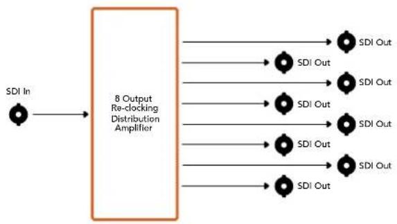
flowchart
graph LR
    A["SDI In"] --> B["8 Output Re-clocking Distribution Amplifier"]
    B --> C1["SDI Out"]
    B --> C2["SDI Out"]
    B --> C3["SDI Out"]
    B --> C4["SDI Out"]
    B --> C5["SDI Out"]
    B --> C6["SDI Out"]
    B --> C7["SDI Out"]
    B --> C8["SDI Out"]
Mini Converter SDI Distribution 4K
接口
flowchart
graph LR
    A["SDI IN 1"] --> B["Cable EQ"]
    C["SDI IN 2"] --> D["Cable EQ"]
    E["SDI IN 3"] --> F["Cable EQ"]
    G["SDI IN 4"] --> H["Cable EQ"]
    B --> I["Central Processor and Firmware"]
    D --> I
    F --> I
    H --> I
    I --> J["Cable Driver"]
    I --> K["Cable Driver"]
    I --> L["Cable Driver"]
    I --> M["Cable Driver"]
    J --> N["SDI OUT 1"]
    K --> O["SDI OUT 2"]
    L --> P["SDI OUT 3"]
    M --> Q["SDI OUT 4"]
    R["USB"] --> I
Mini Converter Sync Generator
- Center Cut (左右切边):
Battery Converter SDI to HDMI
Battery Converter HDMI to SDI
설치 및 사용 설명서
Blackmagic Converters
2018년 06월
한국어

natural_image
Circular portrait photo of a smiling man with short hair, wearing a dark shirt (no text or symbols visible)환영합니다.
natural_image
Front view of a beige electronic device labeled 'N/A/DCB' with ports and internal components (no readable text beyond labels)natural_image
Illustration of a rectangular electronic device with internal components and labeled ports (no readable text or symbols beyond labels)natural_image
Technical line drawing of a mechanical component with no visible text or symbolsnatural_image
3D technical diagram of an electronic component with multiple ports and mounting holes (no text or symbols)natural_image
Illustration of a hand holding a mechanical component with multiple slots and mounting holes (no text or symbols visible)natural_image
Illustration of a hand inserting an orange USB into a computer motherboard (no text or symbols visible)flowchart
graph LR
    A["SDI In"] --> B["Equalizer and 10-bit De-serializer"]
    C["Micro USB"] --> D["Central Processor and Firmware"]
    B --> E["Customizable Video Processor"]
    D --> E
    E --> F["HDMI Video and Audio Formatter"]
    G["Automatic SD/HD/3G-SDI Cable Driver and Re-clocker"] --> H["Loop SDI Out"]
    I["HDMI Out"] --> H
    B --> J["Input automatically detects between SD/HD/3G-SDI"]
    D --> K["Ground"]
Micro Converter HDMI to SDI
2 L - ANALOG or AES/EBU
flowchart
graph TD
    A["SDI In"] --> B["Input automatically detects between SD, HD and 3G-SDI"]
    C["Alt SDI In"] --> D["Central Processor and Firmware"]
    E["USB"] --> D
    B --> F["Redundant Input Automatic Change Over"]
    D --> F
    F --> G["Equalizer, Re-Clocker and 10 bit De-Serializer"]
    G --> H["Customizable Video Processor"]
    H --> I["SDI Audio De-Embedder"]
    I --> J["HDMI Video and Audio Formatter"]
    J --> K["Automatic SD/HD/3G-SDI Cable Driver"]
    K --> L["Loop SDI Out"]
    J --> M["AES/EBU Audio Formatter"]
    J --> N["Audio Digital to Analog with Balanced Output"]
    M --> O["Analog or AES/EBU Audio Out Switch"]
    N --> P["Left Analog Out or AES/EBU Out"]
    N --> Q["Right Analog Out"]
    J --> R["HDMI Out"]
    S["Mini Switches"] --> D
Mini Converter SDI to HDMI 4K
flowchart
graph TD
    A["SDI In"] --> B["Input automatically detects between SD, HD and Ultra HD"]
    C["Alt SDI In"] --> D["Central Processor and Firmware"]
    E["USB"] --> D
    B --> F["Redundant Input Automatic Change Over"]
    D --> G["Equalizer, Re-Clocker and 10 bit De-Serializer"]
    F --> H["Video Processor and Down Converter"]
    G --> H
    H --> I["SDI Audio De-Embedder"]
    I --> J["AES/EBU Audio Formatter"]
    I --> K["Audio Digital to Analog with Balanced Output"]
    I --> L["HDMI Video and Audio Formatter and Instant Lock"]
    J --> M["Automatic SD/HD/Ultra HD Cable Driver"]
    K --> N["Analog or AES/EBU Audio Out Switch"]
    L --> O["Right Analog Out"]
    M --> P["Loop SDI Out"]
    N --> Q["Left Analog Out or AES/EBU Out"]
    O --> R["HDMI Out"]
    S["Mini Switches"] --> D
Mini Converter SDI to HDMI 6G
flowchart
graph TD
    A["SDI In"] --> B["Input automatically detects between SD, HD and Ultra HD"]
    C["Alt SDI In"] --> D["Central Processor and Firmware"]
    E["USB"] --> D
    B --> F["Redundant Input Automatic Change Over"]
    D --> F
    F --> G["Equalizer, Re-Clocker and 10 bit De-Serializer"]
    G --> H["Video Processor and Down Converter"]
    H --> I["SDI Audio De-Embedder"]
    I --> J["AES/EBU Audio Formatter"]
    I --> K["Audio Digital to Analog with Balanced Output"]
    J --> L["Automatic SD/HD/Ultra HD Cable Driver"]
    K --> L
    L --> M["Loop SDI Out"]
    L --> N["Analog or AES/EBU Audio Out Switch"]
    N --> O["Left Analog Out or AES/EBU Out"]
    N --> P["Right Analog Out"]
    L --> Q["HDMI Out"]
    D --> R["Mini Switches"]
    I --> S["HDMI Video and Audio Formatter and Instant Lock"]
    S --> T["Feedback to SI/SW"]
Mini Converter HDMI to SDI
2 L - ANALOG or AES/EBU
2 L - ANALOG or AES/EBU
Mini Converter SDI to Analog
4 L - ANALOG or AES/EBU
other
MiniConverter SDI to Analog | Position | Category | Value | | :--- | :--- | :--- | | 1 | PROCESSING OFF | | | 2 | SDI AUDIO DE-EMBED BIT 0 | | | 3 | SDI AUDIO DE-EMBED BIT 1 | | | 4 | SDI AUDIO DE-EMBED BIT 2 | | | 5 | COMPONENT | | | 6 | SMPTE LEVELS | | | 7 | 7.5 IRE | | | 8 | ANALOG AUDIO | | | 9 | COMPOSITE S-VIDEO | | | 10 | ON OFF | | | 11 | ON OFF | | | 12 | ON OFF | | | 13 | ON OFF | | | 14 | ON OFF | | | 15 | ON OFF | | | 16 | ON OFF | | | 17 | ON OFF | | | 18 | ON OFF | | | 19 | ON OFF | | | 20 | ON OFF | | | 21 | ON OFF | | | 22 | ON OFF | | | 23 | ON OFF | | | 24 | ON OFF | | | 25 | ON OFF | | | 26 | ON OFF | | | 27 | ON OFF | | | 28 | ON OFF | | | 29 | ON OFF | | | 30 | ON OFF | | | 31 | ON OFF | | | 32 | ON OFF | | | 33 | ON OFF | | | 34 | ON OFF | | | 35 | ON OFF | | | 36 | ON OFF | | | 37 | ON OFF | | | 38 | ON OFF | | | 39 | ON OFF | | | 40 | ON OFF | | | 41 | ON OFF | | | 42 | ON OFF | | | 43 | ON OFF | | | 44 | ON OFF | | | 45 | ON OFF | | | 46 | ON OFF | | | 47 | ON OFF | | | 48 | ON OFF | | | 49 | ON OFF | | | 50 | ON OFF | | | 51 | ON OFF | | | 52 | ON OFF | | | 53 | ON OFF | | | 54 | ON OFF | | | 55 | ON OFF | | | 56 | ON OFF | | | 57 | ON OFF | | | 58 | ON OFF | | | 59 | ON OFF | | | 60 | ON OFF | | | 61 | ON OFF | | | 62 | ON OFF | | | 63 | ON OFF | | | 64 | ON OFF | | | 65 | ON OFF | | | 66 | ON OFF | | | 67 | ON OFF | | | 68 | ON OFF | | | 69 | ON OFF | | | 70 | ON OFF | | | 71 | ON OFF | | | 72 | ON OFF | | | 73 | ON OFF | | | 74 | ON OFF | | | 75 | ON OFF | | | 76 | ON OFF | | | 77 | ON OFF | | | 78 | ON OFF | | | 79 | ON OFF | | | 80 | ON OFF | | | 81 | ON OFF | | | 82 | ON OFF | | | 83 | ON OFF | | | 84 | ON OFF | | | 85 | ON OFF | | | 86 | ON OFF | | | 87 | ON OFF | | | 88 | ON OFF | | | 89 | ON OFF | | | 90 | ON OFF | | | 91 | ON OFF | | | 92 | ON OFF | | | 93 | ON OFF | | | 94 | ON OFF | | | 95 | ON OFF | | | 96 | ON OFF | | | 97 | ON OFF | | | 98 | ON OFF | | | 99 | ON OFF | | | (Note: The chart displays a vertical bar chart) with 'ON' and 'ON' labels on the table. The values are estimated based on the 'OFF' and 'ON' labels. The 'ON' labels are not explicitly labeled in the image but are visually represented as bars. The 'OPEN' labels are not explicitly labeled in the image. The 'COMPOSITE S-VIDEO' label is also labeled as 'COMPONENT'. The 'PROCESSING ON' label is also labeled as 'PROCESSING OFF'. The 'Tuggle processing switch to step through down converter mode' is indicated by a small icon at the bottom right.Mini Converter Analog to SDI
Mini Converter SDI to Audio
1 CH 1 ANALOG or CH 1 & 2 AES/EBU
4 CH 4 ANALOG or CH 7 & 8 AES/EBU
1 CH 1 ANALOG or CH 1 & 2 AES/EBU
4 CH 4 ANALOG or CH 7 & 8 AES/EBU
flowchart
graph TD
    A["SDI In"] --> B["Input automatically detects between SD, HD and Ultra HD"]
    C["Alt SDI In"] --> D["Central Processor and Firmware"]
    E["USB"] --> D
    B --> F["Redundant Input Automatic Change Over"]
    D --> F
    F --> G["Equalizer, Re-Clocker and 10 bit De-Serializer"]
    G --> H["SDI Audio De-Embedder"]
    H --> I["AES/EBU Audio Formatter"]
    H --> J["Audio Digital to Analog with Balanced Output"]
    H --> K["AES/EBU Audio Formatter"]
    I --> L["Automatic SD/HD/Ultra HD Cable Driver"]
    J --> L
    K --> L
    L --> M["Loop SDI Out"]

    N["Mini Switches"] --> D
    O["Input"] --> B
    P["Input"] --> C
Mini Converter Audio to SDI
flowchart
graph LR
    A["SDI In"] --> B["Automatic SD/HD/3G-SDI Equalizer"]
    C["SDI Out"] --> D["Automatic SD/HD/3G-SDI Driver"]
    B --> E["Re-Clocker"]
    D --> F["Re-Clocker"]
    E --> G["1310nm Laser Driver with LC Connector"]
    F --> H["1310nm Laser Receiver with LC Connector"]
    G --> I["Optical Out"]
    H --> J["Optical In"]
    style G stroke-dasharray: 5 5
    style H stroke-dasharray: 5 5
    note right of G
        SFP Optical Fiber Transmitter and Receiver Module
    end
Mini Converter Optical Fiber 4K
flowchart
graph TD
    A["USB"] --> B["Central Processor and Firmware"]
    B --> C["Reclocker"]
    C --> D["1310nm Laser Driver with LC Connector"]
    D --> E["Optical Out"]
    F["SDI In"] --> G["Automatic SD/HD/Ultra HD Equalizer"]
    H["SDI Out"] <--_I["Automatic SD/HD/Ultra HD Cable Driver"]
    G --> C
    I --> J["Reclocker"]
    J --> K["1310nm Laser Receiver with LC Connector"]
    K --> L["Optical In"]
    M["SFP Optical Fiber Transmitter and Receiver Module"] -.-> D
    M -.-> K
Mini Converter Optical Fiber 12G
커넥터
1-8 SDI OUT
커넥터
1-8 SDI OUT
flowchart
graph LR
    A["SDI IN 1"] --> B["Cable EQ"]
    C["SDI IN 2"] --> D["Cable EQ"]
    E["SDI IN 3"] --> F["Cable EQ"]
    G["SDI IN 4"] --> H["Cable EQ"]
    B --> I["Central Processor and Firmware"]
    D --> I
    F --> I
    H --> I
    I --> J["Cable Driver"]
    I --> K["Cable Driver"]
    I --> L["Cable Driver"]
    I --> M["Cable Driver"]
    J --> N["SDI OUT 1"]
    K --> O["SDI OUT 2"]
    L --> P["SDI OUT 3"]
    M --> Q["SDI OUT 4"]
    R["USB"] --> I
Mini Converter Sync Generator
| 비디오 포맷 | 스위치 8 | 스위치 7 | 스위치 6 | 스위치 5 | 스위치 4 | 스위치 다이어그램 |
| 525i59.94 NTSC OFF OFF OFF OFF OFF | 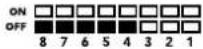 | |||||
| 625i50 PAL | OFF | OFF | OFF | OFF | ON | 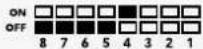 |
| 720p50 OFF OFF OFF ON OFF | 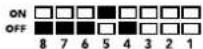 | |||||
| 720p59.94 OFF OFF OFF ON ON | 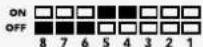 | |||||
| 720p60 OFF OFF ON OFF ON | 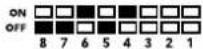 | |||||
| 1080i50 OFF OFF ON OFF ON | 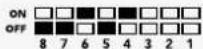 | |||||
| 1080i59.94 OFF OFF ON ON OFF | 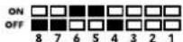 | |||||
| 1080i60 OFF OFF ON ON ON | 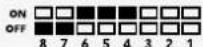 | |||||
| 1080PsF23.98 | OFF | ON | OFF | OFF OFF | 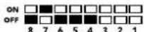 | |
| 1080PsF24 | OFF | ON | OFF | OFF | ON | 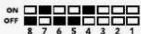 |
| 1080PsF25 | OFF | ON | OFF | ON | OFF | 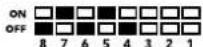 |
| 1080PsF29.97 | OFF | ON | OFF | ON | ON | 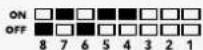 |
| 1080PsF30 | OFF | ON | ON | OFF | OFF | 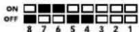 |
| 1080p23.98 | OFF | ON | ON | OFF | ON | 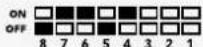 |
| 1080p24 | OFF | ON | ON | ON | OFF | 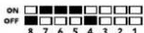 |
| 1080p25 | OFF ON ON ON ON | 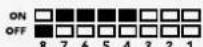 | ||||
| 1080p29.97 | OFF | ON | ON | ON | OFF | 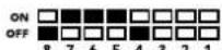 |
| 1080p30 | ON | OFF | OFF | OFF | ON | 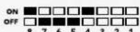 |
| 1080p50 | ON | OFF | OFF | ON | OFF | 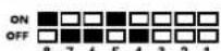 |
| 1080p59.94 | ON | OFF | OFF | ON | ON | 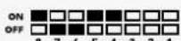 |
| 1080p60 | ON | OFF | ON | OFF | OFF | 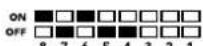 |
컨버터 셋업 유틸리티
Battery Converter SDI to HDMI
2 SDI In주요 SDI 입력(BNC 커넥터).
3 SDI Loop
Battery Converter HDMI to SDI
natural_image
Circular portrait photo of a smiling man with short hair, wearing a dark shirt (no text or symbols visible)Добро пожаловать!
natural_image
Front view of a beige electronic device labeled 'Max Controller / Control Unit' with ports and indicator lights (no readable text beyond labels)natural_image
Illustration of a beige electronic device labeled 'Moltena' with ports and internal components (no readable text beyond labels)natural_image
Technical line drawing of a mechanical component with no visible text or symbolsnatural_image
3D technical diagram of a mechanical or electronic component with multiple ports and mounting holes (no text or symbols)natural_image
Diagram of a computer motherboard with connectors and slots, no text or symbols presentnatural_image
Illustration of a hand inserting an orange USB into a computer motherboard (no text or symbols visible)flowchart
graph TD
    A["Input automatically detects between SD, HD and 3G-SDI"] --> B["Redundant Input Automatic Change Over"]
    C["Alt SDI In"] --> B
    D["USB"] --> E["Central Processor and Firmware"]
    B --> F["Equalizer, Re-Clocker and 10 bit De-Serializer"]
    F --> G["Customizable Video Processor"]
    G --> H["SDI Audio De-Embedder"]
    H --> I["HDMI Video and Audio Formatter"]
    I --> J["Automatic SD/HD/3G-SDI Cable Driver"]
    J --> K["Loop SDI Out"]
    I --> L["AES/EBU Audio Formatter"]
    I --> M["Audio Digital to Analog with Balanced Output"]
    L --> N["Analog or AES/EBU Audio Out Switch"]
    M --> O["Left Analog Out or AES/EBU Out"]
    N --> P["Right Analog Out"]
    O --> Q["HDMI Out"]
    R["Mini Switches"] --> E
Mini Converter SDI to HDMI 4K
- Clip video output to legal levels
- Clip video output to legal levels
Mini Converter SDI to Analog
flowchart
graph TD
    A["SDI In"] --> B["Input automatically detects between SD, HD and 1.5G-SDI"]
    C["Alt SDI In"] --> D["Central Processor and Firmware"]
    E["USB"] --> D
    B --> F["Redundant Input Automatic Change Over"]
    D --> G["Equalizer, Re-Clocker and 10 bit De-Serializer"]
    G --> H["10 bit HD to SD Down Converter"]
    H --> I["SDI Audio De-Embedder"]
    I --> J["AES/EBU Audio Formatter"]
    I --> K["Audio Digital to Analog with Balanced Output"]
    I --> L["12 Bit Digital to Analog SD/HD Video Converter"]
    J --> M["Automatic SD/HD/1.5G-SDI Cable Driver"]
    K --> N["Analog or AES/EBU Audio Out Switch"]
    L --> O["Component output can switch to S-Video and composite"]
    M --> P["Loop SDI Out"]
    N --> Q["Left Analog Out or AES/EBU Out"]
    O --> R["Y"]
    O --> S["R-Y"]
    O --> T["B-Y"]
Mini Converter SDI to Analog 4K
flowchart
graph TD
    A["SDI In"] --> B["Input automatically detects between SD, HD and Ultra HD"]
    C["Alt SDI In"] --> D["Central Processor and Firmware"]
    E["USB"] --> D
    B --> F["Redundant Input Automatic Change Over"]
    D --> G["Equalizer, Re-Clocker and 10 bit De-Serializer"]
    G --> H["10 bit HD to SD Down Converter"]
    H --> I["SDI Audio De-Embedder"]
    I --> J["12 Bit Digital to Analog SD/HD Video Converter"]
    J --> K["Component output can switch to S-Video and composite"]
    L["Automatic SD/HD/Ultra HD Cable Driver"] --> M["Loop SDI Out"]
    N["AES/EBU Audio Formatter"] --> O["Analog or AES/EBU Audio Out Switch"]
    P["Audio Digital to Analog with Balanced Output"] --> Q["Left Analog Out or AES/EBU Out"]
    R["Right Analog Out"] --> S["Y"]
    T["R-Y"] --> U["B-Y"]
    V["B-Y"] --> W["B-Y"]
    X["X"] --> Y["Mini Switches"]
Mini Converter Analog to SDI
Mini Converter SDI to Audio
flowchart
graph TD
    A["SDI In"] --> B["Input automatically detects between SD, HD and Ultra HD"]
    C["Alt SDI In"] --> D["Central Processor and Firmware"]
    E["USB"] --> D
    B --> F["Redundant Input Automatic Change Over"]
    D --> G["Equalizer, Re-Clocker and 10 bit De-Serializer"]
    G --> H["SDI Audio De-Embedder"]
    H --> I["AES/EBU Audio Formatter"]
    H --> J["Audio Digital to Analog with Balanced Output"]
    H --> K["AES/EBU Audio Formatter"]
    I --> L["Automatic SD/HD/Ultra HD Cable Driver"]
    J --> L
    K --> L
    L --> M["Loop SDI Out"]

    N["Mini Switches"] --> D
    O["Input"] --> B
    P["Input"] --> C
    Q["Input"] --> E
Mini Converter Audio to SDI
flowchart
graph LR
    A["SDI In 1"] --> D["SDI Multiplex"]
    B["SDI In 2"] --> D
    C["SDI In 3"] --> D
    E["SDI In 4"] --> D
    F["USB"] --> G["Central Processor and Firmware"]
    D --> H["Equalizer, Re-Clocker and 10 bit De-Serializer"]
    H --> I["Customizable Video Processor"]
    I --> J["HDMI Video and Audio Formatter"]
    J --> K["HDMI Out"]
    D -.-> L["SD/HD/6G-SDI"]
    G -.-> L
Mini Converter SDI Distribution
Разъемы
1-8 SDI OUT
Разъемы
1-8 SDI OUT
flowchart
graph LR
    A["SDI IN 1"] --> B["Cable EQ"]
    C["SDI IN 2"] --> D["Cable EQ"]
    E["SDI IN 3"] --> F["Cable EQ"]
    G["SDI IN 4"] --> H["Cable EQ"]
    B --> I["Central Processor and Firmware"]
    D --> I
    F --> I
    H --> I
    I --> J["Cable Driver"]
    J --> K["SDI OUT 1"]
    I --> L["Cable Driver"]
    L --> M["SDI OUT 2"]
    I --> N["Cable Driver"]
    N --> O["SDI OUT 3"]
    I --> P["Cable Driver"]
    P --> Q["SDI OUT 4"]
    I --> R["USB"]
Mini Converter Sync Generator
Battery Converter SDI to HDMI
Battery Converter HDMI to SDI
natural_image
Circular portrait photo of a smiling man in a dark shirt against a gray background (no text or symbols)Mini Converter Audio to SDI 779
Mini Converter Audio to SDI 4K 783
Mini Converter Optical Fiber 787
Mini Converter Optical Fiber 4K 788
Mini Converter Optical Fiber 12G 789
Mini Converter Quad SDI to HDMI 4K 790
Mini Converter SDI Distribution 791
Mini Converter SDI Distribution 4K 792
Mini Converter SDI Multiplex 4K 793
Mini Converter Sync Generator 796
Mini Converter UpDownCross 799
Mini Converter UpDownCross HD 803
Battery Converter HDMI to SDI 808
Assistenza 810
Garanzia 811
natural_image
Front view of a beige electronic device with ports and an internal connector (no visible text or symbols)natural_image
Illustration of a wireless device with ports and internal components (no text or symbols visible)natural_image
Technical line drawing of a mechanical component with no visible text or symbolsnatural_image
3D technical diagram of an electronic device casing with multiple ports and orange components (no text or symbols)natural_image
Illustration of a hand holding a mechanical component with multiple slots and mounting holes (no text or symbols visible)natural_image
Illustration of a hand inserting an orange USB into a computer motherboard (no text or symbols visible)2 L - ANALOG or AES/EBU
flowchart
graph TD
    A["SDI In"] --> B["Input automatically detects between SD, HD and 3G-SDI"]
    C["Alt SDI In"] --> D["Central Processor and Firmware"]
    E["USB"] --> D
    B --> F["Redundant Input Automatic Change Over"]
    D --> F
    F --> G["Equalizer, Re-Clocker and 10 bit De-Serializer"]
    G --> H["Customizable Video Processor"]
    H --> I["SDI Audio De-Embedder"]
    I --> J["AES/EBU Audio Formatter"]
    I --> K["Audio Digital to Analog with Balanced Output"]
    J --> L["Automatic SD/HD/3G-SDI Cable Driver"]
    K --> L
    L --> M["Loop SDI Out"]
    L --> N["Left Analog Out or AES/EBU Out"]
    L --> O["Right Analog Out"]
    L --> P["HDMI Out"]
    Q["Mini Switches"] --> D
Mini Converter SDI to HDMI 4K
2 L - ANALOG or AES/EBU
- Clip video output to legal levels
flowchart
graph TD
    A["SDI In"] --> B["Input automatically detects between SD, HD and Ultra HD"]
    C["Alt SDI In"] --> D["Central Processor and Firmware"]
    E["USB"] --> D
    B --> F["Redundant Input Automatic Change Over"]
    D --> F
    F --> G["Equalizer, Re-Clocker and 10 bit De-Serializer"]
    G --> H["Video Processor and Down Converter"]
    H --> I["SDI Audio De-Embedder"]
    I --> J["AES/EBU Audio Formatter"]
    I --> K["Audio Digital to Analog with Balanced Output"]
    J --> L["Automatic SD/HD/Ultra HD Cable Driver"]
    K --> L
    L --> M["Loop SDI Out"]
    L --> N["Analog or AES/EBU Audio Out Switch"]
    N --> O["Left Analog Out or AES/EBU Out"]
    N --> P["Right Analog Out"]
    I --> Q["HDMI Video and Audio Formatter and Instant Lock"]
    Q --> R["HDMI Out"]
    D --> S["Mini Switches"]
Mini Converter SDI to HDMI 6G
2 L - ANALOG or AES/EBU
Interruttore 5 - LUT On Loop Off, LUT On Loop On
| Canali audio | Interruttore 4 | Interruttore 3 | Interruttore 2 | Posizione |
| 1 and 2 OFF OFF OFF | 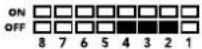 | |||
| 3 and 4 OFF OFF ON | 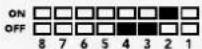 | |||
| 5 and 6 OFF ON OFF | 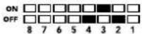 | |||
| 7 and 8 OFF ON ON | 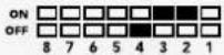 | |||
| 9 and 10 ON OFF OFF | 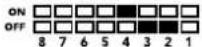 | |||
| 11 and 12 ON OFF ON | 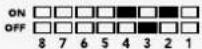 | |||
| 13 and 14 ON ON OFF | 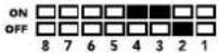 | |||
| 15 and 16 ON ON ON | 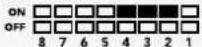 |
- Clip video output to legal levels
flowchart
graph TD
    A["SDI In"] --> B["Input automatically detects between SD, HD and Ultra HD"]
    C["Alt SDI In"] --> D["Central Processor and Firmware"]
    E["USB"] --> D
    B --> F["Redundant Input Automatic Change Over"]
    D --> G["Video Processor and Down Converter"]
    F --> H["Equalizer, Re-Clocker and 10 bit De-Serializer"]
    G --> I["Video Processor and Down Converter"]
    H --> J["SDI Audio De-Embedder"]
    I --> J
    J --> K["AES/EBU Audio Formatter"]
    J --> L["Audio Digital to Analog with Balanced Output"]
    J --> M["HDMI Video and Audio Formatter and Instant Lock"]
    K --> N["Automatic SD/HD/Ultra HD Cable Driver"]
    L --> N
    M --> N
    N --> O["Loop SDI Out"]
    N --> P["Analog or AES/EBU Audio Out Switch"]
    N --> Q["Left Analog Out or AES/EBU Out"]
    N --> R["Right Analog Out"]
    N --> S["HDMI Out"]
    T["Mini Switches"] --> D
Mini Converter HDMI to SDI
2 L - ANALOG or AES/EBU
flowchart
graph TD
    A["Left Analog In or AES/EBU"] --> B["Analog or AES/EBU Audio Switch"]
    C["Right Analog In"] --> D["HDMI In"]
    E["USB"] --> F["Central Processor and Firmware"]
    B --> G["AES/EBU Sample Rate Converter"]
    D --> H["HDMI Video and Audio Decoder"]
    F --> I["Customizable Video Processor"]
    G --> J["SDI Audio Embedder"]
    H --> J
    I --> J
    J --> K["Automatic SD/HD/3G-SDI Cable Driver"]
    K --> L["SDI Out"]
    G --> M["Audio Analog to Digital with Balanced Input"]
    M --> J
    I --> N["Mini Switches"]
Mini Converter HDMI to SDI 4K
2 L - ANALOG or AES/EBU
Mini Converter SDI to Analog
4 L - ANALOG or AES/EBU
4 L - ANALOG or AES/EBU
Mini Converter Analog to SDI
Mini Converter SDI to Audio
1 CH 1 ANALOG or CH 1 & 2 AES/EBU
flowchart
graph TD
    A["SDI In"] --> B["Input automatically detects between SD, HD and 3G-SDI"]
    C["Alt SDI In"] --> D["Central Processor and Firmware"]
    E["USB"] --> D
    B --> F["Redundant Input Automatic Change Over"]
    D --> F
    F --> G["Equalizer, Re-Clocker and 10 bit De-Serializer"]
    G --> H["SDI Audio De-Embedder"]
    H --> I["AES/EBU Audio Formatter"]
    H --> J["Audio Digital to Analog with Balanced Output"]
    H --> K["AES/EBU Audio Formatter"]
    I --> L["Automatic SD/HD/3G-SDI Cable Driver"]
    J --> L
    K --> L
    L --> M["Loop SDI Out"]
    I --> N["Ch 1 Analog or Ch 1&2 AES/EBU"]
    J --> O["Ch 2 Analog or Ch 3&4 AES/EBU"]
    K --> P["Ch 3 Analog or Ch 5&6 AES/EBU"]
    L --> Q["Ch 4 Analog or Ch 7&8 AES/EBU"]
    M --> R["Output"]
    N --> R
    O --> R
    P --> R
    Q --> R
Mini Converter SDI to Audio 4K
1 CH 1 ANALOG or CH 1 & 2 AES/EBU
Mini Converter Audio to SDI
1 CH 1 ANALOG or CH 1 & 2 AES/EBU
4 CH 4 ANALOG or CH 7 & 8 AES/EBU
flowchart
graph LR
    A["SDI In"] --> B["Automatic SD/HD/3G-SDI Equalizer"]
    C["SDI Out"] --> D["Automatic SD/HD/3G-SDI Driver"]
    B --> E["Re-Clocker"]
    D --> F["Re-Clocker"]
    E --> G["1310nm Laser Driver with LC Connector"]
    F --> H["1310nm Laser Receiver with LC Connector"]
    G --> I["Optical Out"]
    H --> J["Optical In"]
    style G stroke-dasharray: 5 5
    style H stroke-dasharray: 5 5
    note right of G
        SFP Optical Fiber Transmitter and Receiver Module
    end
Mini Converter Optical Fiber 4K
flowchart
graph TD
    A["USB"] --> B["Central Processor and Firmware"]
    B --> C["Reclocker"]
    C --> D["1310nm Laser Driver with LC Connector"]
    D --> E["Optical Out"]
    F["SDI In"] --> G["Automatic SD/HD/Ultra HD Equalizer"]
    G --> H["Reclocker"]
    H --> I["1310nm Laser Receiver with LC Connector"]
    I --> J["Optical In"]
    K["SDI Out"] --> L["Automatic SD/HD/Ultra HD Cable Driver"]
    L --> M["Reclocker"]
    M --> N["SFP Optical Fiber Transmitter and Receiver Module"]
Mini Converter Optical Fiber 12G
flowchart
graph LR
    A["SDI In"] --> B["Automatic SD/HD/12G-SDI Equalizer"]
    C["SDI Out"] --> D["Automatic SD/HD/12G-SDI Driver"]
    B --> E["Re-Clocker"]
    D --> F["Re-Clocker"]
    E --> G["1310nm Laser Driver with LC Connector"]
    F --> H["1310nm Laser Receiver with LC Connector"]
    G --> I["Optical Out"]
    H --> J["Optical In"]
    style G stroke-dasharray: 5 5
    style H stroke-dasharray: 5 5
    note right of G
        SFP Optical Fiber Transmitter and Receiver Module
    end
Mini Converter Quad SDI to HDMI 4K
flowchart
graph LR
    A["SDI In 1"] --> D["SDI Multiplex"]
    B["SDI In 2"] --> D
    C["SDI In 3"] --> D
    E["SDI In 4"] --> D
    F["USB"] --> G["Central Processor and Firmware"]
    D --> H["Equalizer, Re-Clocker and 10 bit De-Serializer"]
    H --> I["Customizable Video Processor"]
    I --> J["HDMI Video and Audio Formatter"]
    J --> K["HDMI Out"]
Mini Converter SDI Distribution
Connettori
1-8 SDI OUT
Connettori
1-8 SDI OUT
| Conversione | Interruttore 8 | Interruttore 7 | Interruttore 6 | Interruttore 1 | Posizione |
| 6G/3G-SDI single link in 3G/1.5G-SDI dual link | ON ON ON ON | 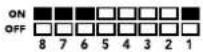 | |||
| 6G-SDI single link in 1.5G-SDI quad link | ON OFF ON ON | 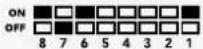 | |||
| 3G/1.5G-SDI dual link in 6G/3G-SDI single link | ON ON OFF ON | 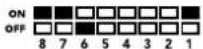 | |||
| 3G-SDI dual link in 1.5G-SDI quad link | ON OFF OFF ON | 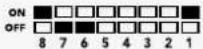 | |||
| 1.5G-SDI quad link in 6G-SDI single link | OFF ON ON ON | 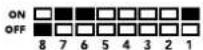 | |||
| 1.5G-SDI quad link in 3G-SDI dual link | OFF OFF ON ON | 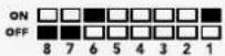 | |||
Lo schema di Mini Converter SDI Multiplex 4K
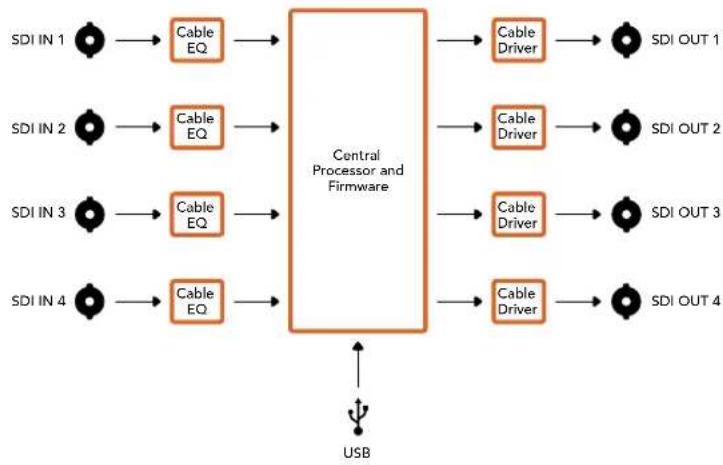
flowchart
graph LR
    A["SDI IN 1"] --> B["Cable EQ"]
    C["SDI IN 2"] --> D["Cable EQ"]
    E["SDI IN 3"] --> F["Cable EQ"]
    G["SDI IN 4"] --> H["Cable EQ"]
    B --> I["Central Processor and Firmware"]
    D --> I
    F --> I
    H --> I
    I --> J["Cable Driver"]
    I --> K["Cable Driver"]
    I --> L["Cable Driver"]
    I --> M["Cable Driver"]
    J --> N["SDI OUT 1"]
    K --> O["SDI OUT 2"]
    L --> P["SDI OUT 3"]
    M --> Q["SDI OUT 4"]
    R["USB"] --> I
Mini Converter Sync Generator
Battery Converter SDI to HDMI
Battery Converter HDMI to SDI
natural_image
Circular portrait photo of a smiling man in a dark polo shirt against a textured gray background (no text or symbols)Bem-vindo
natural_image
Illustration of a beige electronic device with internal components and labeled ports (no readable text or symbols)natural_image
Technical line drawing of a mechanical component with no visible text or symbolsnatural_image
3D technical diagram of a mechanical or electronic component with multiple ports and mounting holes (no text or symbols)natural_image
Technical illustration of a mechanical component with multiple slots and mounting holes, no text or symbols presentnatural_image
Illustration of a hand inserting an orange USB into a computer motherboard (no text or symbols visible)flowchart
graph LR
    A["SDI In"] --> B["Equalizer and 10-bit De-serializer"]
    C["Micro USB"] --> D["Central Processor and Firmware"]
    B --> E["Customizable Video Processor"]
    D --> E
    E --> F["HDMI Video and Audio Formatter"]
    F --> G["Automatic SD/HD/3G-SDI Cable Driver and Re-clocker"]
    G --> H["Loop SDI Out"]
    F --> I["HDMI Out"]
    B --> J["Input automatically detects between SD/HD/3G-SDI"]
    D --> K["Feedback to Central Processor and Firmware"]
Micro Converter HDMI to SDI
2 L - ANALOG or AES/EBU
Chave 8 - Analog Audio, AES/EBU Audio
2 L - ANALOG or AES/EBU
Chave 8 - Analog Audio, AES/EBU Audio
- Clip Video Output to Legal Levels
flowchart
graph TD
    A["SDI In"] --> B["Redundant Input Automatic Change Over"]
    C["Alt SDI In"] --> D["Central Processor and Firmware"]
    E["USB"] --> D
    B --> F["Equalizer, Re-Clocker and 10 bit De-Serializer"]
    D --> G["Video Processor and Down Converter"]
    F --> H["SDI Audio De-Embedder"]
    G --> H
    H --> I["AES/EBU Audio Formatter"]
    H --> J["Audio Digital to Analog with Balanced Output"]
    I --> K["Automatic SD/HD/Ultra HD Cable Driver"]
    J --> K
    K --> L["Loop SDI Out"]
    K --> M["Analog or AES/EBU Audio Out Switch"]
    K --> N["Left Analog Out or AES/EBU Out"]
    K --> O["Right Analog Out"]
    K --> P["HDMI Out"]
    D --> Q["Mini Switches"]
    Q --> R["Output"]
Mini Converter SDI to HDMI 6G
2 L - ANALOG ou AES/EBU
Saída SDI via conector BNC.
6 ALT SDI IN
Chave 8 - Analog Audio, AES/EBU Audio
Chave 7 - LUT Off, LUT On
Chave 5 - LUT On Loop Off, LUT On Loop On
- Clip Video Output to Legal Levels
flowchart
graph TD
    A["SDI In"] --> B["Input automatically detects between SD, HD and Ultra HD"]
    C["Alt SDI In"] --> D["Central Processor and Firmware"]
    E["USB"] --> D
    B --> F["Redundant Input Automatic Change Over"]
    D --> F
    F --> G["Equalizer, Re-Clocker and 10 bit De-Serializer"]
    G --> H["Video Processor and Down Converter"]
    H --> I["SDI Audio De-Embedder"]
    I --> J["AES/EBU Audio Formatter"]
    I --> K["Audio Digital to Analog with Balanced Output"]
    J --> L["Automatic SD/HD/Ultra HD Cable Driver"]
    K --> L
    L --> M["Loop SDI Out"]
    L --> N["Analog or AES/EBU Audio Out Switch"]
    L --> O["Left Analog Out or AES/EBU Out"]
    L --> P["Right Analog Out"]
    L --> Q["HDMI Out"]
    D --> R["Mini Switches"]
    R --> S["Output"]
Mini Converter HDMI to SDI
2 L - ANALOG ou AES/EBU
Chave 8 - Analog Audio, AES/EBU Audio
flowchart
graph TD
    A["Left Analog In or AES/EBU"] --> B["Analog or AES/EBU Audio Switch"]
    C["Right Analog In"] --> D["HDMI In"]
    E["USB"] --> F["Central Processor and Firmware"]
    B --> G["AES/EBU Sample Rate Converter"]
    D --> H["HDMI Video and Audio Decoder"]
    F --> I["Customizable Video Processor"]
    G --> J["SDI Audio Embedder"]
    H --> J
    I --> J
    J --> K["Automatic SD/HD/3G-SDI Cable Driver"]
    K --> L["SDI Out"]
    G --> M["Audio Analog to Digital with Balanced Input"]
    H --> N["Mini Switches"]
    I --> O["SDI Out"]
Mini Converter HDMI to SDI 4K
2 L - ANALOG ou AES/EBU
Saída SDI via conector BNC.
6 SDI OUT
Segunda saída SDI.
7 POWER +12V
Chave 8 - Analog Audio, AES/EBU Audio
Chaves 2, 1 - Select Format Bit 1,0
2 L - ANALOG ou AES/EBU
Saída SDI via conector BNC.
6 SDI OUT
Segunda saída SDI.
7 POWER +12V
Chave 8 - Analog Audio, AES/EBU Audio
Chaves 2, 1 - Select Format Bit 1,0
Mini Converter SDI to Analog
Chave 8 - Analog Audio, AES/EBU Audio
4 L - ANALOG ou AES/EBU
Saída SDI via conector BNC.
8 ALT SDI IN
Chave 8 - Analog Audio, AES/EBU Audio
flowchart
graph TD
    A["SDI In"] --> B["Input automatically detects between SD, HD and 1.5G-SDI"]
    C["Alt SDI In"] --> D["Central Processor and Firmware"]
    E["USB"] --> D
    B --> F["Redundant Input Automatic Change Over"]
    D --> F
    F --> G["Equalizer, Re-Clocker and 10 bit De-Serializer"]
    G --> H["10 bit HD to SD Down Converter"]
    H --> I["SDI Audio De-Embedder"]
    I --> J["AES/EBU Audio Formatter"]
    I --> K["Audio Digital to Analog with Balanced Output"]
    I --> L["12 Bit Digital to Analog SD/HD Video Converter"]
    J --> M["Automatic SD/HD/1.5G-SDI Cable Driver"]
    K --> N["Analog or AES/EBU Audio Out Switch"]
    L --> O["Component output can switch to S-Video and composite"]
    M --> P["Loop SDI Out"]
    N --> Q["Left Analog Out or AES/EBU Out"]
    O --> R["Y"]
    O --> S["R-Y"]
    O --> T["B-Y"]
Mini Converter Analog to SDI
7 SDI OUT Saída SDI via conector BNC.
8 SDI OUT Segunda saída SDI.
Chave 8 - Analog Audio, AES/EBU Audio
Mini Converter SDI to Audio
Chave 8 - Analog Audio, AES/EBU Audio
flowchart
graph TD
    A["SDI In"] --> B["Input automatically detects between SD, HD and 3G-SDI"]
    C["Alt SDI In"] --> D["Central Processor and Firmware"]
    E["USB"] --> D
    B --> F["Redundant Input Automatic Change Over"]
    D --> F
    F --> G["Equalizer, Re-Clocker and 10 bit De-Serializer"]
    G --> H["SDI Audio De-Embedder"]
    H --> I["AES/EBU Audio Formatter"]
    H --> J["Audio Digital to Analog with Balanced Output"]
    H --> K["AES/EBU Audio Formatter"]
    I --> L["Automatic SD/HD/3G-SDI Cable Driver"]
    J --> L
    K --> L
    L --> M["Loop SDI Out"]
    I --> N["Ch 1 Analog or Ch 1&2 AES/EBU"]
    J --> O["Ch 2 Analog or Ch 3&4 AES/EBU"]
    K --> P["Ch 3 Analog or Ch 5&6 AES/EBU"]
    L --> Q["Ch 4 Analog or Ch 7&8 AES/EBU"]
    M --> R["Output"]
    N --> R
    O --> R
    P --> R
    Q --> R
Mini Converter SDI to Audio 4K
Chave 8 - Analog Audio, AES/EBU Audio
Mini Converter Audio to SDI
Chave 8 - Analog Audio, AES/EBU Audio
Chave 8 - Analog Audio, AES/EBU Audio
flowchart
graph TD
    A["MINI CONVERTer Audio to SDI 4K"] --> B["OFF"]
    A --> C["ON"]
    B --> D["ANALOG AUDIO"]
    B --> E["AES/EBU AUDIO"]
    C --> F["NO SAMPLE RATE CONVERSION"]
    D --> G["AUDIO GROUP BIT 1"]
    E --> H["AUDIO GROUP BIT 0"]
    F --> I["CH 4 or AES 7&8 DISABLE OFF"]
    F --> J["CH 4 or AES 7&8 DISABLE ON"]
    G --> K["CH 3 or AES 5&6 DISABLE OFF"]
    G --> L["CH 3 or AES 5&6 DISABLE ON"]
    H --> M["CH 2 or AES 3&4 DISABLE OFF"]
    H --> N["CH 2 or AES 3&4 DISABLE ON"]
    I --> O["CH 1 or AES 1&2 DISABLE OFF"]
    I --> P["CH 1 or AES 1&2 DISABLE ON"]
    J --> Q["CH 1 or AES 1&2 DISABLE ON"]
    K --> R["9-16"]
    L --> S["9-12"]
    M --> T["13-16"]
    N --> U["9-16"]
    R --> V["SWITCHES"]
    S --> W["SWITCHES"]
    T --> X["SWITCHES"]
    U --> Y["SWITCHES"]
flowchart
graph TD
    A["USB"] --> B["Central Processor and Firmware"]
    C["SDI In"] --> D["Automatic SD/HD/Ultra HD Equalizer"]
    E["SDI Out"] --> F["Automatic SD/HD/Ultra HD Cable Driver"]
    D --> G["Reclocker"]
    F --> H["Reclocker"]
    G --> I["1310nm Laser Driver with LC Connector"]
    H --> J["1310nm Laser Receiver with LC Connector"]
    I --> K["Optical Out"]
    J --> L["Optical In"]
    style G stroke-dasharray: 5 5
    style H stroke-dasharray: 5 5
    style I stroke-dasharray: 5 5
    style J stroke-dasharray: 5 5
    style K stroke-dasharray: 5 5
    style L stroke-dasharray: 5 5
Mini Converter Optical Fiber 12G
flowchart
graph LR
    A["SDI In 1"] --> D["SDI Multiplex"]
    B["SDI In 2"] --> D
    C["SDI In 3"] --> D
    E["SDI In 4"] --> D
    F["USB"] --> G["Central Processor and Firmware"]
    D --> H["Equalizer, Re-Clocker and 10 bit De-Serializer"]
    H --> I["Customizable Video Processor"]
    I --> J["HDMI Video and Audio Formatter"]
    J --> K["HDMI Out"]
    D -.-> L["SD/HD/6G-SDI"]
Mini Converter SDI Distribution
Conectores
1-8 SDI Out
flowchart
graph LR
    A["SDI IN 1"] --> B["Cable EQ"]
    C["SDI IN 2"] --> D["Cable EQ"]
    E["SDI IN 3"] --> F["Cable EQ"]
    G["SDI IN 4"] --> H["Cable EQ"]
    B --> I["Central Processor and Firmware"]
    D --> I
    F --> I
    H --> I
    I --> J["Cable Driver"]
    I --> K["Cable Driver"]
    I --> L["Cable Driver"]
    I --> M["Cable Driver"]
    J --> N["SDI OUT 1"]
    K --> O["SDI OUT 2"]
    L --> P["SDI OUT 3"]
    M --> Q["SDI OUT 4"]
    R["USB"] --> I
Mini Converter Sync Generator
other
Mini Converter Sync Generator | Section | Category | Value | | :--- | :--- | :--- | | 1 | SYNC REF FORMAT BIT 0 | 720p / 50 | | 2 | SYNC REF FORMAT BIT 1 | 720p / 59.94 | | 3 | SYNC REF FORMAT BIT 2 | 1080psf / 24 | | 4 | SYNC REF FORMAT BIT 3 | 1080psf / 23.98 | | 5 | 1080i / 50 | ON OFF | | 6 | 1080i / 59.94 | ON OFF | | 7 | 1080i / 59.94 | ON OFF | | 8 | OFF | ON OFF | NETSC | Off | ON OFF | Off | ON OFF | Off | ON OFF | Off | ON OFF | Off | ON OFF | Off | ON OFF | Off | ON OFF | Off | ON OFF | Off | ON OFF | Off | ON OFF | Off | ON OFF | Off | ON OFF | Off | ON OFF | Off | ON OFF | Off | ON OFF | Off | ON OFF | Off | ON OFF | Off - Off | Off - Off | Off - Off | Off - Off | Off - Off | Off - Off | Off - Off | Off - Off | Off - Off | Off - Off | Off - Off | Off - Off | Off - Off | Off - Off | Off - Off | Off - Off | Off - Off | Off - Off | Off - Off | Off - Off | Off - On | Off - On | Off - On | Off - On | Off - On | Off - On | Off - On | Off - On | Off - On | Off - On | Off - On | Off - On | Off - On | Off - On | Off - On | Off - On | Off - On | Off - On | Off - On | Off - On | Off - ON | Off - ON | Off - ON | Off - ON | Off - ON | Off - ON | Off - ON | Off - ON | Off - ON | Off - ON | Off - ON | Off - ON | FORMAT SELECTION TABLEnatural_image
Diagram showing a circle being converted into a rectangular frame, with no text or symbols present.16:9 Ratio Display4:3 Ratio Image
Battery Converter SDI to HDMI
Entrada SDI principal via conector BNC.
3 SDI Loop
Battery Converter HDMI to SDI
natural_image
Circular portrait photo of a smiling man in a dark shirt against a textured gray background (no text or symbols)Hoş Geldiniz
Blackmagic Design CEO
İçindekiler
natural_image
Front view of a gray electronic device with ports and an internal connector (no visible text or symbols)natural_image
Illustration of a wireless device with ports and internal components (no text or symbols visible)natural_image
Technical line drawing of a mechanical connector or housing assembly (no text or symbols)natural_image
3D technical diagram of an electronic device casing with multiple ports and mounting holes (no text or symbols)natural_image
Illustration of a hand holding a mechanical component with multiple slots and a central slot (no text or symbols visible)natural_image
Illustration of a hand inserting an orange USB into a computer motherboard (no text or symbols visible)MINI Converter SDI to HDMI
2 L (Sol) - ANALOG veya AES/EBU
flowchart
graph TD
    A["SDI In"] --> B["Input automatically detects between SD, HD and 3G-SDI"]
    C["Alt SDI In"] --> D["Central Processor and Firmware"]
    E["USB"] --> D
    B --> F["Redundant Input Automatic Change Over"]
    D --> F
    F --> G["Equalizer, Re-Clocker and 10 bit De-Serializer"]
    G --> H["Customizable Video Processor"]
    H --> I["SDI Audio De-Embedder"]
    I --> J["HDMI Video and Audio Formatter"]
    J --> K["Automatic SD/HD/3G-SDI Cable Driver"]
    K --> L["Loop SDI Out"]
    J --> M["AES/EBU Audio Formatter"]
    J --> N["Audio Digital to Analog with Balanced Output"]
    M --> O["Analog or AES/EBU Audio Out Switch"]
    N --> P["Left Analog Out or AES/EBU Out"]
    N --> Q["Right Analog Out"]
    J --> R["HDMI Out"]
    S["Mini Switches"] --> D
Mini Converter SDI to HDMI 4K
2 L (Sol) - ANALOG veya AES/EBU
flowchart
graph TD
    A["SDI In"] --> B["Redundant Input Automatic Change Over"]
    C["Alt SDI In"] --> B
    D["USB"] --> E["Central Processor and Firmware"]
    B --> F["Equalizer, Re-Clocker and 10 bit De-Serializer"]
    E --> G["Video Processor and Down Converter"]
    F --> H["SDI Audio De-Embedder"]
    G --> H
    H --> I["AES/EBU Audio Formatter"]
    H --> J["Audio Digital to Analog with Balanced Output"]
    H --> K["HDMI Video and Audio Formatter and Instant Lock"]
    I --> L["Automatic SD/HD/Ultra HD Cable Driver"]
    J --> L
    K --> M["Loop SDI Out"]
    L --> N["Analog or AES/EBU Audio Out Switch"]
    M --> O["Left Analog Out or AES/EBU Out"]
    N --> P["Right Analog Out"]
    O --> Q["HDMI Out"]
    P --> Q
    Q --> R["Mini Switches"]
MINI Converter SDI to HDMI 6G
2 L (Sol) - ANALOG veya AES/EBU
flowchart
graph TD
    A["SDI In"] --> B["Input automatically detects between SD, HD and Ultra HD"]
    C["Alt SDI In"] --> D["Central Processor and Firmware"]
    E["USB"] --> D
    B --> F["Redundant Input Automatic Change Over"]
    D --> F
    F --> G["Equalizer, Re-Clocker and 10 bit De-Serializer"]
    G --> H["Video Processor and Down Converter"]
    H --> I["SDI Audio De-Embedder"]
    I --> J["AES/EBU Audio Formatter"]
    I --> K["Audio Digital to Analog with Balanced Output"]
    J --> L["Automatic SD/HD/Ultra HD Cable Driver"]
    K --> L
    L --> M["Loop SDI Out"]
    L --> N["Analog or AES/EBU Audio Out Switch"]
    L --> O["Left Analog Out or AES/EBU Out"]
    L --> P["Right Analog Out"]
    L --> Q["HDMI Out"]
    I --> R["HDMI Video and Audio Formatter and Instant Lock"]
    R --> S["Mini Switches"]
Mini Converter HDMI to SDI
2 L (Sol) - ANALOG veya AES/EBU
1 L (Sol) - ANALOG veya AES/EBU
Anahtar 2, 1 - Format Seç Bit 1,0
Mini Converter SDI to Analog
4 L (Sol) - ANALOG veya AES/EBU
other
MiniConverter SDI to Analog | Position | Audio Status | Bit Level | Off/ON | | :--- | :--- | :--- | :--- | | 1 | Processing OFF | ON | Toggle processing switch to step through down converter mode (■) | | 2 | Processing OFF | ON | Toggle processing switch to step through down converter mode (□) | | 3 | SDI AUDIO DE-EMBED BIT 0 | ON | Toggle processing switch to step through down converter mode (■) | | 4 | SDI AUDIO DE-EMBED BIT 1 | ON | Toggle processing switch to step through down converter mode (□) | | 5 | COMPONENT | COMPOSITE S-VIDEO | Toggle processing switch to step through down converter mode (□) | | 6 | SMPTE LEVELS | BETACAM LEVELS | Toggle processing switch to step through down converter mode (□) | | 7 | 7.5 IRE | 0.0 IRE | Toggle processing switch to step through down converter mode (□) | | 8 | ANALOG AUDIO | AES/EBU AUDIO | Toggle processing switch to step through down converter mode (□) | SDI AUDIO DE-EMBED BIT 2 | ON | OFF | Toggle processing switch to step through down converter mode (□) | | 9 | 7 + 8 | OFF | Toggle processing switch to step through down converter mode (□) | | 10 | 9 + 10 | OFF | Toggle processing switch to step through down converter mode (□) | | 11 | 11 + 12 | OFF | Toggle processing switch to step through down converter mode (□) | | 12 | SDI AUDIO DE-EMBED BIT 0 | ON | Toggle processing switch to step through down converter mode (□) | | 13 | SDI AUDIO DE-EMBED BIT 1 | ON | Toggle processing switch to step through down converter mode (□) | | 14 | SDI AUDIO DE-EMBED BIT 2 | ON | Toggle processing switch to step through down converter mode (□) | | 15 | COMPONENT | COMPOSITE S-VIDEO | Toggle processing switch to step through down converter mode (□) | | 16 | SMPTE LEVELS | BETACAM LEVELS | Toggle processing switch to step through down converter mode (□) | | 17 | 7.5 IRE | AES/EBU AUDIO | Toggle processing switch to step through down converter mode (□) | | 18 | ANALOG AUDIO | AES/EBU AUDIO | Toggle processing switch to step through down converter mode (□) | SDI AUDIO DE-EMBED BIT 3 | ON | OFF | Toggle processing switch to step through down converter mode (□) | | 19 | COMPONENT | COMPOSITE S-VIDEO | Toggle processing switch to step through down converter mode (□) | SDI AUDIO DE-EMBED BIT 4 | 7 + 8 | OFF | Toggle processing switch to step through down converter mode (□) | | 20 | SMPTE LEVELS | BETACAM LEVELS | Toggle processing switch to step through down converter mode (□) | | 21 | ANALOG AUDIO | AES/EBU AUDIO | Toggle processing switch to step through down converter mode (□) | SDI AUDIO DE-EMBED BIT 5 | ON | OFF | Toggle processing switch to step through down converter mode (□) | | 22 | COMPONENT | COMPOSITE S-VIDEO | Toggle processing switch to step through down converter mode (□) | SDI AUDIO DE-EMBED BIT 6 | 7 + 8 | OFF | Toggle processing switch to step through down converter mode (□) | | 23 | SMPTE LEVELS | BETACAM LEVELS | Toggle processing switch to step through down converter mode (□) | | 24 | ANALOG AUDIO | AES/EBU AUDIO | Toggle processing switch to step through down converter mode (□) | SDI AUDIO DE-EMBED BIT 7 | ON | OFF | Toggle processing switch to step through down converter mode (□) | | 25 | COMPONENT | COMPOSITE S-VIDEO | Toggle processing switch to step through down converter mode (□) | SDI AUDIO DE-EMBED BIT 8 | 7 + 8 | OFF | Toggle processing switch to step through down converter mode (□) | SDI AUDIO DE-EMBED BIT 9 | 7 + 8 | OFF | Toggle processing switch to step through down converter mode (□) | SDI AUDIO DE-EMBED BIT 10 | ON | OFF | Toggle processing switch to step through down converter mode (□) | SDI AUDIO DE-EMBED BIT 11 | ON | OFF | Toggle processing switch to step through down converter mode (□) | SDI AUDIO DE-EMBED BIT 12 | ON | OFF | Toggle processing switch to step through down converter mode (□) | SDI AUDIO DE-EMBED BIT 13 | ON | OFF | Toggle processing switch to step through down converter mode (□) | SDI AUDIO DE-EMBED BIT 14 | ON | OFF | Toggle processing switch to step through down converter mode (□) | SDI AUDIO DE-EMBED BIT 15+Mini Converter Analog to SDI
Mini Converter SDI to Audio
flowchart
graph TD
    A["SDI In"] --> B["Input automatically detects between SD, HD and Ultra HD"]
    C["Alt SDI In"] --> D["Central Processor and Firmware"]
    E["USB"] --> D
    B --> F["Redundant Input Automatic Change Over"]
    D --> F
    F --> G["Equalizer, Re-Clocker and 10 bit De-Serializer"]
    G --> H["SDI Audio De-Embedder"]
    H --> I["AES/EBU Audio Formatter"]
    H --> J["Audio Digital to Analog with Balanced Output"]
    H --> K["AES/EBU Audio Formatter"]
    I --> L["Automatic SD/HD/Ultra HD Cable Driver"]
    J --> L
    K --> L
    L --> M["Loop SDI Out"]

    N["Mini Switches"] --> D
    O["Input"] --> B
    P["Input"] --> C
    Q["Input"] --> E
    R["Input"] --> N
    S["Input"] --> O
    T["Input"] --> P
    U["Input"] --> Q
    V["Input"] --> R
Mini Converter Audio to SDI
flowchart
graph TD
    A["USB"] --> B["Central Processor and Firmware"]
    C["SDI In"] --> D["Automatic SD/HD/Ultra HD Equalizer"]
    E["SDI Out"] --> F["Automatic SD/HD/Ultra HD Cable Driver"]
    D --> G["Reclocker"]
    F --> H["Reclocker"]
    G --> I["1310nm Laser Driver with LC Connector"]
    H --> J["1310nm Laser Receiver with LC Connector"]
    I --> K["Optical Out"]
    J --> L["Optical In"]
    style G stroke-dasharray: 5 5
    style H stroke-dasharray: 5 5
    style I stroke-dasharray: 5 5
    style J stroke-dasharray: 5 5
    style K stroke-dasharray: 5 5
    style L stroke-dasharray: 5 5
Mini Converter Optical Fiber 12G
flowchart
graph LR
    A["SDI In"] --> B["Automatic SD/HD/12G-SDI Equalizer"]
    B --> C["Re-Clocker"]
    C --> D["1310nm Laser Driver with LC Connector"]
    D --> E["Optical Out"]
    F["SDI Out"] --> G["Automatic SD/HD/12G-SDI Driver"]
    G --> H["Re-Clocker"]
    H --> I["1310nm Laser Receiver with LC Connector"]
    I --> J["Optical In"]
    K["SFP Optical Fiber Transmitter and Receiver Module"] --> L["Re-Clocker"]
    L --> M["1310nm Laser Driver with LC Connector"]
    M --> N["Optical Out"]
Mini Converter Quad SDI to HDMI 4K
Konektörler
1-8 SDI ÇIKIŞI
Konektörler
1-8 SDI ÇIKIŞI
flowchart
graph LR
    A["SDI IN 1"] --> B["Cable EQ"]
    C["SDI IN 2"] --> D["Cable EQ"]
    E["SDI IN 3"] --> F["Cable EQ"]
    G["SDI IN 4"] --> H["Cable EQ"]
    B --> I["Central Processor and Firmware"]
    D --> I
    F --> I
    H --> I
    I --> J["Cable Driver"]
    I --> K["Cable Driver"]
    I --> L["Cable Driver"]
    I --> M["Cable Driver"]
    J --> N["SDI OUT 1"]
    K --> O["SDI OUT 2"]
    L --> P["SDI OUT 3"]
    M --> Q["SDI OUT 4"]
    R["USB"] --> I
Mini Converter Sync Generator
Battery Converter SDI to HDMI
- Installation and Operation Manual
- Blackmagic Converters
- Languages
- English 3
- Welcome
- Contents
- Getting Started
- Plugging in Power
- Micro Converter
- Battery Converters
- Plugging in Video
- Optical Fiber Connectors
- Fail Safe Alternate SDI inputs
- Plugging in Audio
- Jack Audio Connectors
- Installing Administration Software
- Installing Blackmagic Converters Setup
- Installation on Mac OS X
- Installation on Windows
- Updating the Internal Software
- Updating Mini Converter SDI Distribution 4K
- Changing Settings
- Changing Settings using Switches
- Changing Settings using Blackmagic Converters Setup
- About Tab
- Blackmagic Converter Models
- Teranex Mini Converters
- Blackmagic Micro Converters
- Micro Converter SDI to HDMI
- Connectors
- SDI In
- SDI Loop
- Micro USB / Power
- HDMI Out
- Blackmagic Converters Setup Settings
- Processing menu
- Micro Converter SDI to HDMI Block Diagram
- Micro Converter HDMI to SDI
- SDI OUT
- SDI OUT
- HDMI In
- Micro Converter HDMI to SDI Block Diagram
- Micro Converter BiDirectional SDI/HDMI
- HDMI Out
- HDMI In
- SDI Out
- SDI In
- Blackmagic Mini Converters
- Mini Converter SDI to HDMI
- HDMI
- L - ANALOG or AES/EBU
- R - ANALOG
- MINI-B USB PORT
- SDI OUT
- ALT SDI IN
- SDI IN
- POWER +12V
- Switches
- Switch 8 - Analog Audio, AES/EBU Audio
- Switch 4 - SDI Audio De-Embed Bit 2
- Switch 3 - SDI Audio De-Embed Bit 1
- Switch 2 - SDI Audio De-Embed Bit 0
- Switch 1 - Processing Off - Processing On
- Mini Switch Settings Example
- Output Levels menu
- Mini Converter SDI to HDMI Block Diagram
- Mini Converter SDI to HDMI 4K
- - HDMI Instant Lock
- - Clip Video Output to Legal Levels
- Mini Converter SDI to HDMI 6G
- Switch 7 - LUT Off, LUT On
- Switch 6 - LUT 1, LUT2
- Switch 5 - LUT On Loop Off, LUT On Loop On
- Switch 1 - HDMI Instant Lock Off, HDMI Instant Lock On
- - 33 Point 3D LUT
- - What is a 3D LUT?
- Mini Converter HDMI to SDI
- SDI OUT
- POWER +12V
- Switch 7 - HDMI Audio - Input Audio
- Input Levels menu
- Mini Converter HDMI to SDI Block Diagram
- Mini Converter HDMI to SDI 4K
- Switches 2, 1 - Select Format Bit 1,0
- AUTO - switch 1 to OFF, switch 2 to OFF.
- FORCE TO HD - switch 1 to OFF, switch 2 to ON.
- FORCE TO ULTRA HD - Switch 1 to ON, Switch 2 to OFF.
- Mini Converter HDMI to SDI 4K Block Diagram
- Mini Converter HDMI to SDI 6G
- Switch 7 - HDMI Audio, Input Audio
- Switch 6 - 3G Level B Output (Normal), 3G Level A Output
- AUTO - switch 1 to OFF, switch 2 to OFF
- FORCE TO HD - switch 1 to OFF, switch 2 to ON
- FORCE TO ULTRA HD - Switch 1 to ON, Switch 2 to OFF
- Mini Converter SDI to Analog
- Switch 7 - 7.5 IRE - 0.0 IRE
- Switch 6 - SMPTE Levels - Betacam Levels
- Switch 5 - Component, Composite or S-Video
- Switch 4 - SDI Audio De-Embed B it 2
- Mini Converter SDI to Analog 4K
- Switch 4, 3 and 2 - SDI Audio De-Embed
- Mini Switch Settings Example:
- Mini Converter Analog to SDI
- Switch 4 - Composite - S-Video
- Mini Converter SDI to Audio
- CH 1 ANALOG or CH 1 & 2 AES/EBU
- CH 2 Analog or CH 3 & 4 AES/EBU
- CH 3 Analog or CH 5 & 6 AES/EBU
- CH 4 Analog or CH 7 & 8 AES/EBU
- MINI-B USB PORT
- ALT SDI IN
- SDI IN
- POWER +12V
- Switch 6 - Audio Group Bit 1
- Switch 5 - Audio Group Bit 0
- Mini Converter SDI to Audio 4K
- Mini Converter Audio to SDI
- Switch 7 - Sample Rate Conversion, No Sample Rate Conversion
- Embedding or Disabling Channels
- Audio Channel De-Embed or Disable Settings
- Mini Converter Audio to SDI 4K
- Mini Converter Optical Fiber
- Mini Converter Optical Fiber 4K
- Mini Converter Optical Fiber 12G
- Optical Out
- Optical In
- SDI Out
- SDI In
- Power +6 to 36V
- Mini Converter Quad SDI to HDMI 4K
- SDI In 1
- SDI In 2
- SDI In 3
- SDI In 4
- HDMI
- Mini Converter SDI Distribution
- 1-8 SDI Out
- 9SDIn
- Power +12V
- Mini Converter SDI Distribution 4K
- Mini Converter SDI Multiplex 4K
- Power +12V
- SDI In 1
- SDI In 2
- SDI In 3
- SDI In 4
- Mini-B USB port
- SDI Out 1
- SDI Out 2
- SDI Out 3
- SDI Out 4
- Switches 8, 7 and 6 - Format Conversion
- Switch 1 - Processing ON/OFF
- Mini Converter Sync Generator
- 1-6 REF Out
- Mini-B USB port
- Power+12V
- Switch 4, 3, 2 and 1 - SYNC REF FORMAT BIT 3, 2, 1 and 0
- Mini ConverterUpDownCross
- 1-5 SDI Out
- SDI LOOP
- REF IN
- Switch 8 - Aspect Ratio Conversion
- Up conversion
- Down conversion
- Mini ConverterUpDownCross HD
- HDMI IN
- REF IN
- USB-C PORT
- 6-7 SDI OUT
- HDMIOUT
- POWER +6 to 36V
- Switch 2 - Level A and Level B 3G-SDI
- Switches 4 - 8
- Converter Setup Utility
- Aspect Ratio for Standard Definition
- Blackmagic Battery Converters
- Battery Converter SDI to HDMI
- Mini-B USB port
- SDI In
- SDI Loop
- HDMI
- ON BATT OFF
- Power +12V
- Battery Converter HDMI to SDI
- Help
- Getting Help
- Blackmagic Design Online Support Pages
- Blackmagic Design Forum
- Contacting Blackmagic Design Support
- Checking the Software Version Currently Installed
- How to Get the Latest Software Updates
- Warranty
- Limited Warranty
- ようこそ
- 目次
- はじめに 95
- 管理ソフトウェアの インストール 98
- 設定の変更 101
- ヘルプ 180
- はじめに
- 接続
- Bienvenue
- Connecteurs
- 1-8 Sorties SDI
- Willkommen
- Inhaltsverzeichnis
- Erste Schritte 275
- Hilfe 360
- Garantie 361
- Erste Schritte
- Switch 1 – PROCESSING OFF, PROCESSING ON
- Switch 5 – LUT ON LOOP OFF, LUT ON LOOP ON
- Switches 2, 1 – SELECT FORMAT BIT 1,0
- Switch 8 – ANALOG AUDIO, AES/EBU AUDIO
- Switch 7 - 7.5 IRE, 0.0 IRE
- Switch 1 - PROCESSING OFF, PROCESSING ON
- Anschlüsse
- Switch 1 – PROCESSING ON/OFF
- Bienvenido
- Conexiones de audio
- Conectores
- Interruptor 3 - Aislar audio SDI, bit 1
- Interruptor 2 - Aislar audio SDI, bit 0
- Interruptor 4 - Aislar audio SDI, bit 2
- Interruptor 8 – Audio analógico, AES/EBU
- Opciones del programa Blackmagic Converters Setup
- L - ANALOG or AES/EBU
- Conexiones
- 9SDIIN
- 安装操作手册
- 欢迎辞
- Blackmagic Battery Converter系列 537
- 帮助 540
- 入门
- Output Levels (输出电平) 菜单
- ·HDMI Instant Lock (HDMI即时锁定)
- - Clip HDMI Output to Legal Levels (HDMI限幅输出到合法电平)
- - Clip Video Output to Legal Levels (HDMI限幅输出到合法电平)
- 接口
- SDI IN
- - Center Cut (左右切边):
- 환영합니다.
- 커넥터
- 컨버터 셋업 유틸리티
- Добро пожаловать!
- Разъемы
- Interruttore 5 - LUT On Loop Off, LUT On Loop On
- Connettori
- Bem-vindo
- Chave 8 - Analog Audio, AES/EBU Audio
- L - ANALOG ou AES/EBU
- Chave 7 - LUT Off, LUT On
- Chave 5 - LUT On Loop Off, LUT On Loop On
- Chaves 2, 1 - Select Format Bit 1,0
- Hoş Geldiniz
- İçindekiler
- L (Sol) - ANALOG veya AES/EBU
- L (Sol) - ANALOG veya AES/EBU
- Anahtar 2, 1 - Format Seç Bit 1,0
- Konektörler
- 1-8 SDI ÇIKIŞI
Brand : Blackmagic Design
Model : Mini Converter
Category : Receiver