
Whisperwind - Fan Klarstein - Free user manual and instructions
Find the device manual for free Whisperwind Klarstein in PDF.


| Product type | Floor/standing fan |
| Brand | Klarstein |
| Model | Whisperwind |
| Article numbers | 10034670, 10034671 |
| Power supply | 220-240 V ~ 50/60 Hz |
| Power | 30 W |
| Maximum air speed | 4.58 m/s |
| Maximum airflow | 25.52 m³/min |
| Speed levels | 12 |
| Oscillation function | Yes (adjustable angles: 30°, 60°, 90°, 120°) |
| Timer | 0-12 hours (0.5 h increments up to 6 h, then 1 h) |
| Modes | Natural, Night, Normal |
| Remote control | Yes (included) |
| Assembly required | Base, tube, head, grilles, blades |
| Cleaning | Damp cloth, no corrosive detergents or hard objects |
| Safety | Do not immerse in water, do not cover, unplug before maintenance |
Frequently Asked Questions - Whisperwind Klarstein
User questions about Whisperwind Klarstein
0 question about this device. Answer the ones you know or ask your own.
Ask a new question about this device
Download the instructions for your Fan in PDF format for free! Find your manual Whisperwind - Klarstein and take your electronic device back in hand. On this page are published all the documents necessary for the use of your device. Whisperwind by Klarstein.
USER MANUAL Whisperwind Klarstein
INHALTSVERZEICHNIS
natural_image
Diagram showing a screwdriver inserted into a component with a spiral pattern, no text or symbols presentDISPLAY UND TASTENFUNKTIONEN
Bedienfeld
Timer einstellen
Member of Berlin Brands Group
Handwerkerstr. 11
15366 Dahlwitz-Hoppegarten
Deutschland
natural_image
Symbol of a trash bin crossed with a diagonal line, no text or numbers presentBerlin Brands Group UK Ltd
PO Box 1145
Oxford, OX1 9UW
United Kingdom
Dear Customer,
Congratulations on purchasing this device. Please read the following instructions carefully and follow them to prevent possible damages. We assume no liability for damage caused by disregard of the instructions and improper use. Scan the QR code to get access to the latest user manual and more product information.

CONTENT
Safety Instructions 18
Single Parts 20
Product Overview 21
Assembly 22
Display and Key Functions 23
Operation 24
Cleaning and Care 27
Disposal Considerations 28
Manufacturer & Importer (UK) 28
TECHNICAL DATA
| Item number 10034670, 10034671 | |
| Power supply 220-240 V ~ 50/60 Hz | |
| Power 30 W | |
| Maximum air velocity 4,58 m/s | |
| Maximum air flow rate 25,52 m^3/min |
SAFETY INSTRUCTIONS
- Remove the packaging and make sure that the appliance is intact. If in doubt, do not use it and contact qualified personnel only.
- Packaging materials (plastic bags, polystyrene, staples etc.) Must be kept out of the reach of children as they could be hazardous.
- This device may be only used by children 8 years old or older and persons with limited physical, sensory and mental capabilities and / or lack of experience and knowledge, provided that they have been instructed in use of the device by a responsible person who understands the associated risks.
- Before connecting the appliance, check that the appliance rating corresponds to the mains rating.
- This appliance must only be used for the purpose for which it has been manufactured. As a stand fan. The manufacturer is not responsible for any damage caused by improper or incorrect use.
- The installation/assembly of the device will be made according to the indications of the manufacturer. A wrong procedure may cause damages to persons, animals or objects, for which the manufacturer cannot be considered responsible
- Before cleaning or carrying out maintenance on the appliance, disconnect it from the electrical mains by removing the plug from the electrical outlet or by switching off the system switch.
- If the appliance is faulty and/or operating incorrectly, switch it off without tampering with it. If the above is disregarded, the safety of the appliance may be compromised.
- If the supply cord is damaged, it must be replaced by the manufacturer, its service agent or similarly qualified persons in order to avoid a hazard.
- Do not power the device using multiple sockets.
- Do not use adapters and/or extension cable
- The device must not be switched on using external timers and/or other remote control devices which are not specified in this manual.
- Do not use or store the device near heat sources (heaters, stoves).
- Do not dip the device in water or other liquids; in case the accidental fall in the water do not try to take it out, but first of all unplug immediately the power cable from the socket.
- If you use the device for the first time, make sure to remove any label or protective sheet which blocks its proper functioning.
- Plug and unplug the power cable with dry hands and hold it firmly.
- Before plugging the plug into a wall outlet, make sure that the unit is switched off.
• Always unplug the power cable to avoid the overheating and avoid stretching it. - Make sure that all air intakes and outlets are free and not covered so that the unit does not overheat.
-
Avoid placing the power cable on abrasive or sharp surfaces or in positions where it can be damaged easily.
-
Do not hang the fan on the wall or ceiling unless this type of installation is provided and explained in this manual.
- Place the device at a proper distance from the objects or surrounding walls making sure that its functioning will not cause accidental damages.
- Do not use the device near gas stoves or open flames in general.
- Do not use the device near curtains or textiles.
- Do not cover the device during functioning.
- Do not expose yourself for a long period to the air flow generated by the device because it can cause damage to the health
- If the fan must be stored for a long period and is not used regularly, place the fan in its original packaging in a dry place.
- Always remember to unplug the power cable of the device if it is not used for a long period, before storing, cleaning or performing any maintenance operation.
- Do not use the appliance in the presence of potentially flammable or explosive liquids or gases.
- This product is intended for household use only and not for commercial / industrial or outdoor use.
SINGLE PARTS
| 1 | 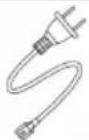 | Power cord |
| 2 |  | Base |
| 3 | 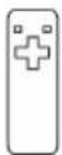 | Remote control |
| 4 | 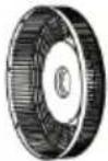 | Rear protective grille |
| 5 | [6CS7] | Rear guard nut |
| 6 | 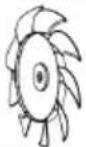 | Fan blades |
| 7 |  | Nut of fan blades |
| 8 | 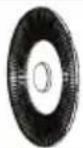 | Front protective grille |
| 9 | [HTZW] | Connecting tube |
| 10 | 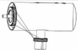 | Fan head |
| 11 | [62WD] | Allen wrench |
| 12 | [69WD] | Allen screw m6 |
| 13 | [3706] | Screw (protective grid) |
PRODUCT OVERVIEW
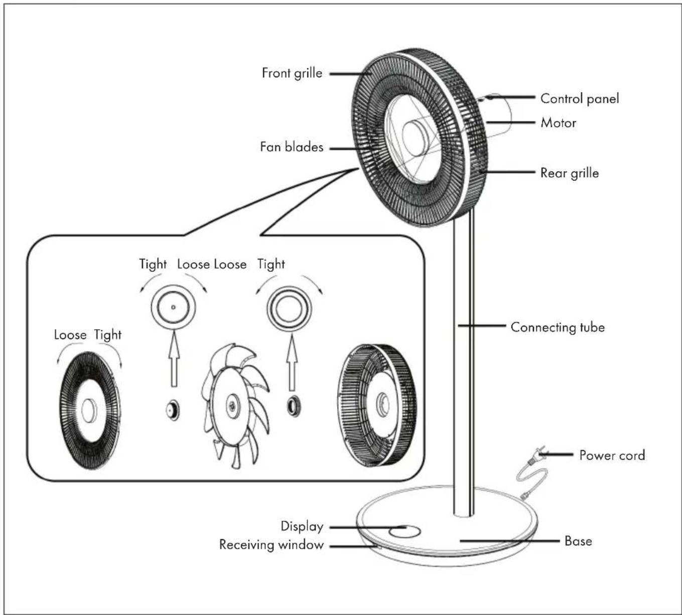
ASSEMBLY
Installation of the protective grilles
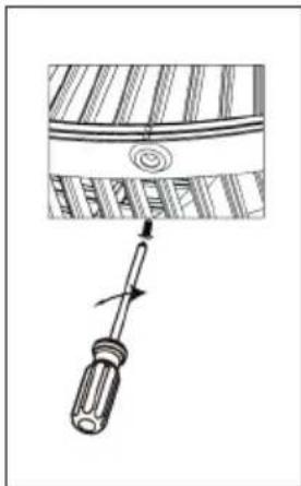
- Mount the front guard grille as shown in the Device Overview and then rotate it clockwise to bring the positioning point into a vertical position.
- Tighten the screws to complete the installation.
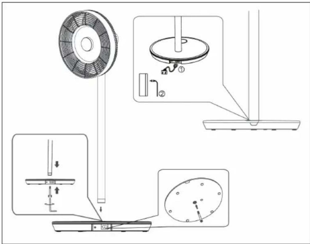
Installing the Base
Place the connecting tube on the base. Insert the Allen screw M6 into the base from below and tighten the screw clockwise with the Allen wrench.
natural_image
Diagram of a screwdriver inserted into a component, showing motion direction (no text or symbols)Installing the Power Supply
- Plug one side of the power cord into the rectangular connector on the base of the unit.
- Plug the power plug at the other end of the power cord into the wall outlet. A beep will sound as soon as the unit is connected.
Installation of the fan head
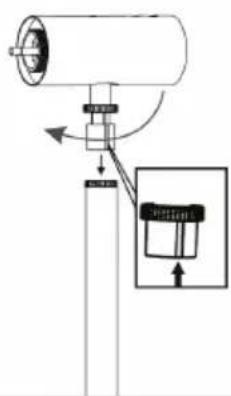
- Place the fan head on the capillary tube by aligning the groove on the capillary tube (see figure).
- Tighten the capillary tube nut. Finish installing the fan head by making sure it does not wobble.
natural_image
Diagram of a mechanical device with a cylindrical component and a magnified inset showing a bucket (no text or symbols)DISPLAY AND KEY FUNCTIONS
Control panel
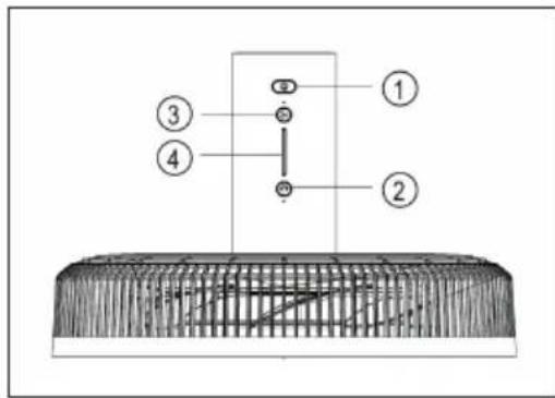
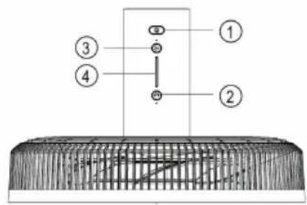
1 On/Off
2 Swing
3 Speed
4 Indicator light
Display
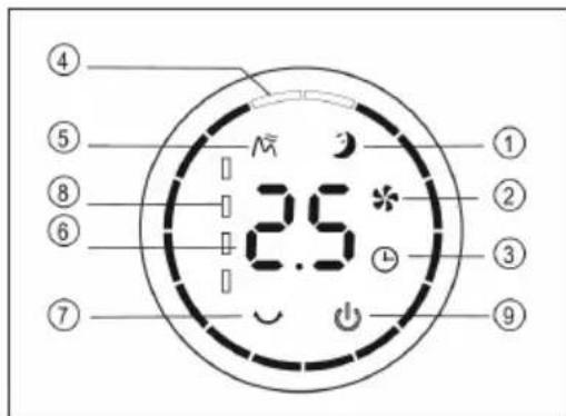
1 Sleep mode
2 Normal mode
3 Timer
4 Swing angle
5 Natural mode
6 Timer/Speed
7 Swing
8 Battery level indicator
9 On/Off
Remote Control
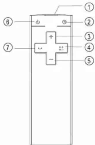
1 Transmitter
2 Timer
3 Increase speed
4 Mode
5 Decrease speed
6 On/Off
7 Swing
OPERATION
Switch device on/off
- Press the ON/OFF button on the fan head. A beep will sound and indicate that the fan is starting.
- The speed controller lights up, the fan symbol in the digital display lights up and the fan starts operating.
- Press the button again to switch off the fan.
Setting the speed
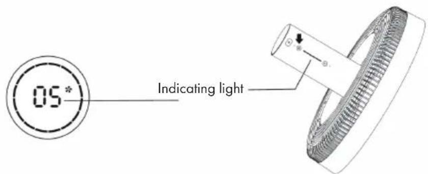
Press the SPEED button repeatedly to select the speed level from 1 to 12. There is a display on the fan head indicating the currently set speed.
Start swing function
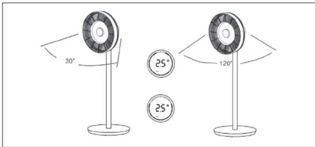
Press the SWING button on the fan head. A beep will sound and the fan will begin to oscillate back and forth. The default angle is 30^ . The swing indicator lights up and the green circle of the digital indicator lights up. Press and hold this button to stop the oscillation.
Setting the swing angle
Press the SWING button on the fan head. A beep will sound and the fan will begin to oscillate back and forth. The default angle is 300^ . The swing indicator lights up and the green circle of the digital indicator lights up. Press the SWING button several times to select one of the following swing angles: 30^ > 60^ > 90^ > 120^ . The green circle of the digital display changes accordingly. Press and hold this key to end the swing function.
Note: The same setting is made on the remote control.
Setting the timer
Press the TIMER button on the fan head. As soon as the time indicator lights up after the beep, you can set the off timer. Press the button repeatedly to set the timer between 0 and 12 hours.
• From 0-6 hours, the time can be set in 0.5-hour increments.
• From 6-12 hours, the time can be set in 1-hour increments.
• If you select 0 hours, the timer function is cancelled.
Note: When setting the timer using the remote control, first press the TIMER button and then use the (+) or (-) buttons to set the desired time. Wait 6 seconds until the set time is automatically set.
Set mode
Press the MODE button repeatedly to set one of the following modes: Natural Mode > Sleep Mode > Normal Mode. Depending on the mode, the fan speed will vary/change at certain intervals.
Wireless use
(applies only to the wireless model)
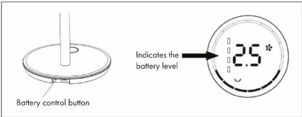
Unplug the power cord from the outlet and remove the power cord from the base. Press the battery control button on the base. A beep will sound, indicating that the unit is now powered by the built-in battery. Press the ON/OFF button on the fan head or remote control to start the fan.
CLEANING AND CARE
- Switch off the fan before cleaning and unplug it from the wall outlet.
- Remove the front grille, rear grille and fan blades by loosening the nuts as shown:
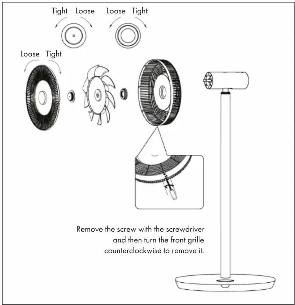
- Wipe the surface with a damp cloth. Do not clean with hard objects such as steel wool or caustic detergents such as disinfectants to avoid surface scratches and damage.
• To move the unit, unplug it from the wall outlet first.
DISPOSAL CONSIDERATIONS

natural_image
Symbol of a trash bin crossed with a diagonal line, no text or numbers presentIf there is a legal regulation for the disposal of electrical and electronic devices in your country, this symbol on the product or on the packaging indicates that this product must not be disposed of with household waste. Instead, it must be taken to a collection point for the recycling of electrical and electronic equipment. By disposing of it in accordance with the rules, you are protecting the environment and the health of your fellow human beings from negative consequences. For information about the recycling and disposal of this product, please contact your local authority or your household waste disposal service.
This product contains batteries. If there is a legal regulation for the disposal of batteries in your country, the batteries must not be disposed of with household waste. Find out about local regulations for disposing of batteries. By disposing of them in accordance with the rules, you are protecting the environment and the health of your fellow human beings from negative consequences.
MANUFACTURER & IMPORTER (UK)
Manufacturer:
Chal-Tec GmbH, Wallstrasse 16, 10179 Berlin, Germany.
Importer for Great Britain:
Berlin Brands Group UK Ltd
PO Box 1145
Oxford, OX1 9UW
United Kingdom
Estimado cliente:
ÍNDICE DE CONTENIDOS
natural_image
Diagram showing a screwdriver inserted into a component with a spiral pattern, no text or symbols presentnatural_image
Symbol of a trash bin crossed with a diagonal line, no text or numbers presentBerlin Brands Group UK Ltd
PO Box 1145
Oxford, OX1 9UW
United Kingdom
Chère cliente, cher client,
SOMMAIRE
natural_image
Diagram showing a screwdriver inserted into a component with a spiral pattern on the cover (no text or symbols)natural_image
Symbol of a trash bin crossed with a diagonal line, no text or numbers presentBerlin Brands Group UK Ltd
PO Box 1145
Oxford, OX1 9UW
United Kingdom
Gentile cliente,
INDICE
natural_image
Diagram showing a screwdriver inserted into a component with a spiral head (no text or symbols)natural_image
Diagram of a mechanical device with a cylindrical component and a magnified inset showing internal components (no text or symbols)Impostare il timer
natural_image
Simple line drawing of a circular base with a vertical rod and a small attached component (no text or symbols)natural_image
Symbol of a trash bin crossed with a diagonal line, no text or labels presentPRODUTTORE E IMPORTATORE (UK)
Produttore:
Chal-Tec GmbH, Wallstraße 16, 10179 Berlino, Germania.
Berlin Brands Group UK Ltd
PO Box 1145
Oxford, OX1 9UW
United Kingdom

bar
| Category | Value | |---|---| | Category 1 | 100 | | Category 2 | 100 | | Category 3 | 100 | | Category 4 | 100 | | Category 5 | 100 | | Category 6 | 100 | | Category 7 | 100 | | Category 8 | 100 | | Category 9 | 100 | | Category 10 | 100 | | Category 11 | 100 | | Category 12 | 100 | | Category 13 | 100 | | Category 14 | 100 | | Category 15 | 100 | | Category 16 | 100 | | Category 17 | 100 | | Category 18 | 100 | | Category 19 | 100 | | Category 20 | 100 | | Category 21 | 100 | | Category 22 | 100 | | Category 23 | 100 | | Category 24 | 100 | | Category 25 | 100 | | Category 26 | 100 | | Category 27 | 100 | | Category 28 | 100 | | Category 29 | 100 | | Category 30 | 100 | | Category 31 | 100 | | Category 32 | 100 | | Category 33 | 100 | | Category 34 | 100 | | Category 35 | 100 | | Category 36 | 100 | | Category 37 | 100 | | Category 38 | 100 | | Category 39 | 100 | | Category 40 | 100 | | Category 41 | 100 | | Category 42 | 100 | | Category 43 | 100 | | Category 44 | 100 | | Category 45 | 100 | | Category 46 | 100 | | Category 47 | 100 | | Category 48 | 100 | | Category 49 | 100 | | Category 50 | 100 | | Category 51 | 100 | | Category 52 | 100 | | Category 53 | 100 | | Category 54 | 100 | | Category 55 | 100 | | Category 56 | 100 | | Category 57 | 100 | | Category 58 | 100 | | Category 59 | 100 | | Category 60 | 100 | | Category 61 | 100 | | Category 62 | 100 | | Category 63 | 100 | | Category 64 | 100 | | Category 65 | 100 | | Category 66 | 100 | | Category 67 | 100 | | Category 68 | 100 | | Category 69 | 100 | | Category 70 | 100 | | Category 71 | 100 | | Category 72 | 100 | | Category 73 | 100 | | Category 74 | 100 | | Category 75 | 100 | | Category 76 | 100 | | Category 77 | 100 | | Category 78 | 100 | | Category 79 | 100 | | Category 80 | 100 | | Category 81 | 100 | | Category 82 | 100 | | Category 83 | 100 | | Category 84 | 100 | | Category 85 | 100 | | Category 86 | 100 | | Category 87 | 100 | | Category 88 | 100 | | Category 89 | 100 | | Category 90 | 100 | | Category 91 | 100 | | Category 92 | 100 | | Category 93 | 100 | | Category 94 | 100 | | Category 95 | 100 | | Category 96 | 100 | | Category 97 | 100 | | Category 98 | 100 | | Category 99 | 100 | | Total (Total) = [sum of bars] / [values] * (sum of bars + bars) * (sum of bars + bars) * (sum of bars + bars). The values in the table represent the sum of the bars and the corresponding sum of the bars. There is no additional data series or categories specified in the code.
KLARSTEIN
- INHALTSVERZEICHNIS
- DISPLAY UND TASTENFUNKTIONEN
- Bedienfeld
- Timer einstellen
- Member of Berlin Brands Group
- Handwerkerstr. 11
- Dahlwitz-Hoppegarten
- Deutschland
- Dear Customer,
- CONTENT
- SAFETY INSTRUCTIONS
- SINGLE PARTS
- PRODUCT OVERVIEW
- ASSEMBLY
- Installation of the protective grilles
- Installing the Base
- Installing the Power Supply
- Installation of the fan head
- DISPLAY AND KEY FUNCTIONS
- Control panel
- Display
- Remote Control
- OPERATION
- Switch device on/off
- Setting the speed
- Start swing function
- Setting the swing angle
- Setting the timer
- Set mode
- Wireless use
- CLEANING AND CARE
- DISPOSAL CONSIDERATIONS
- MANUFACTURER & IMPORTER (UK)
- Manufacturer:
- Importer for Great Britain:
- Estimado cliente:
- ÍNDICE DE CONTENIDOS
- Chère cliente, cher client,
- SOMMAIRE
- Gentile cliente,
- INDICE
- Impostare il timer
- PRODUTTORE E IMPORTATORE (UK)
- Produttore:
- KLARSTEIN
Brand : Klarstein
Model : Whisperwind
Category : Fan