
ZenBreeze Smart - Fan Klarstein - Free user manual and instructions
Find the device manual for free ZenBreeze Smart Klarstein in PDF.

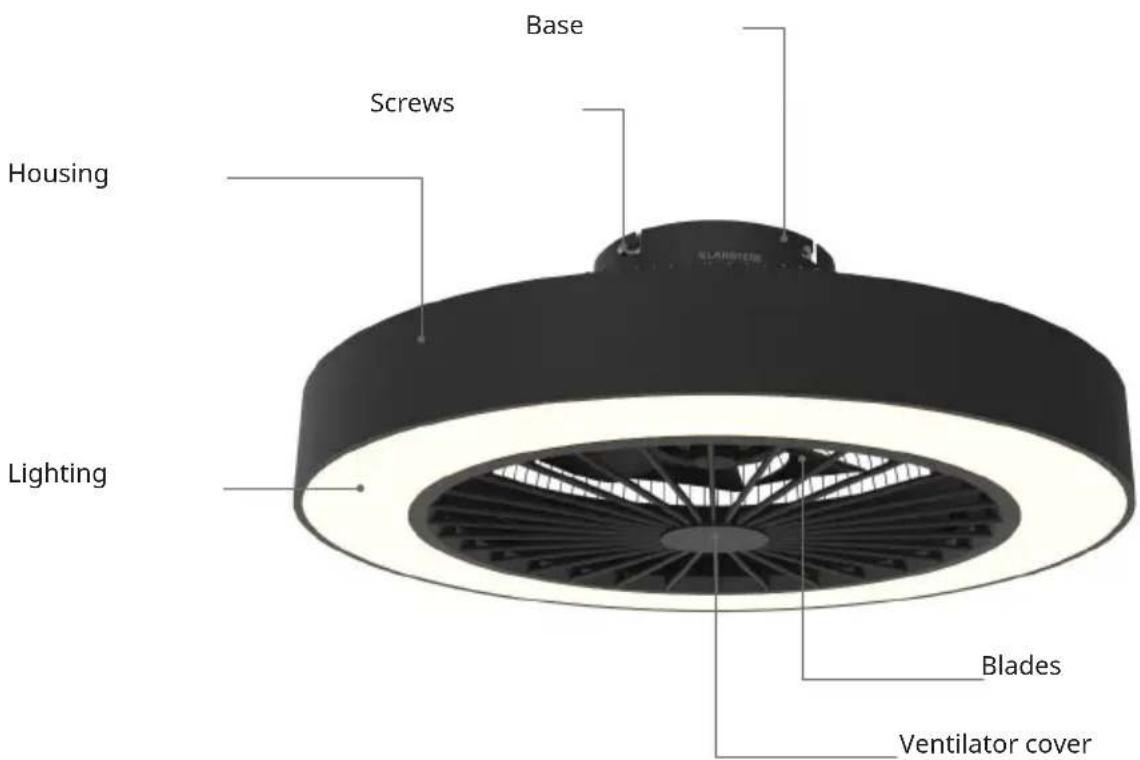
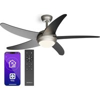
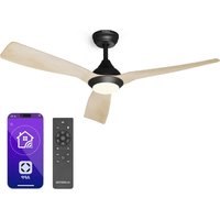
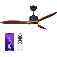
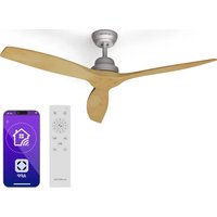
| Product Type | Ceiling fan with LED lighting |
| Brand | Klarstein |
| Model | ZenBreeze Smart |
| Power Supply | 220-240 V ~ 50 Hz |
| Fan Power | 20 W |
| Lamp Type | Integrated LED |
| Color Temperature | 3000 K / 4500 K / 6500 K (adjustable) |
| Color Rendering Index (CRI) | ≥ 80 |
| Maximum Airflow | 77 m³/min |
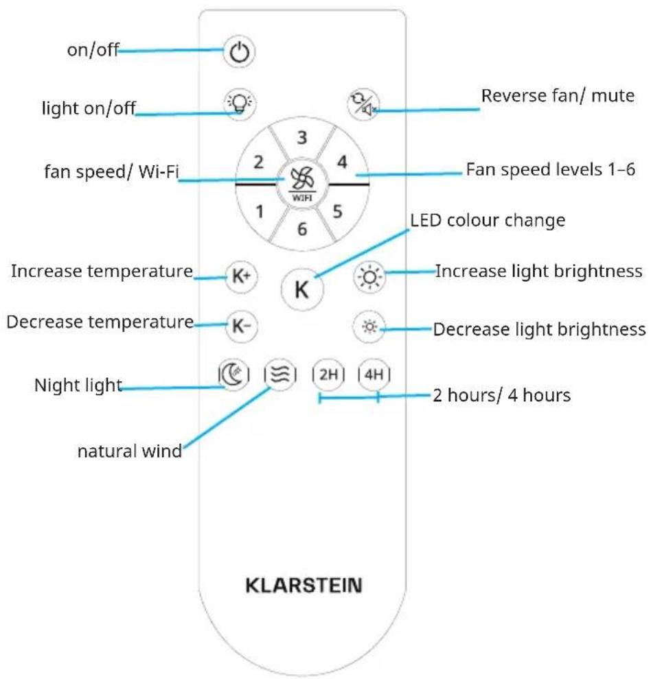
| Number of Speeds | 6 adjustable speeds |
| Natural Wind Mode | Yes |
| Reverse Function (Summer/Winter) | Yes |
| Timer | 2 h / 4 h |
| Connectivity | WiFi 2.4 GHz (802.11 b/g/n) via Klarstein app |
| WiFi Radio Frequency Power (max.) | 20 dBm |
| Remote Control Included | Yes |
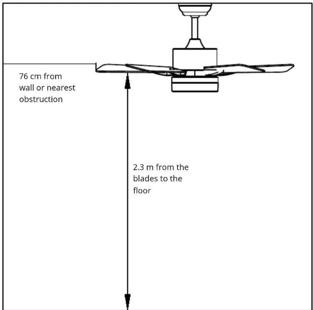
| Minimum Blade-to-Floor Distance | 2.3 m |
| Minimum Blade-to-Wall Distance | 76 cm |
| Minimum Hook Load Capacity | 100 kg |
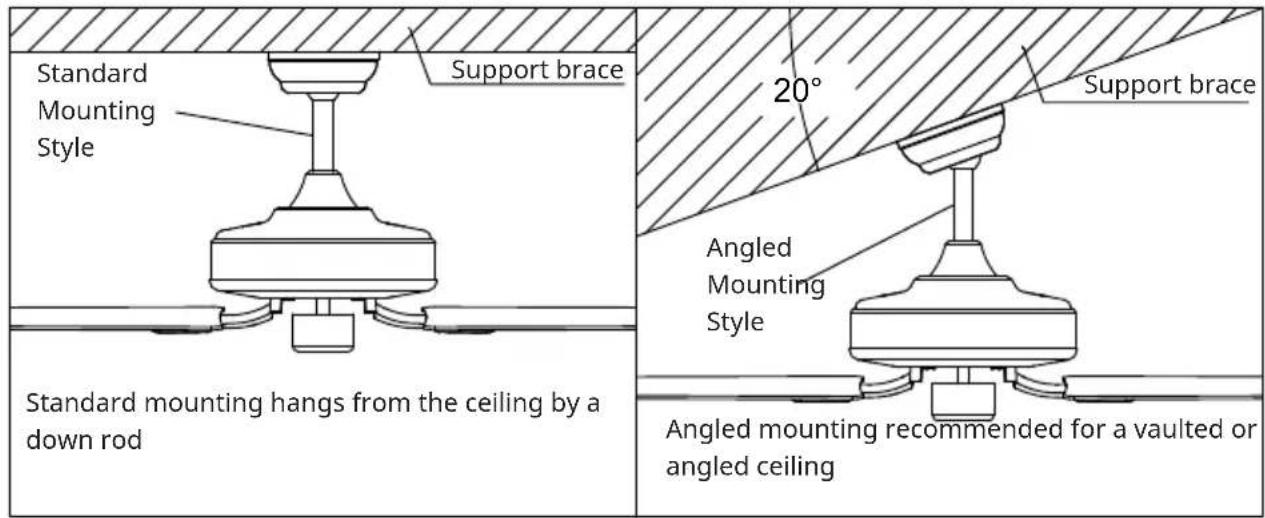
| Mounting Type | Normal or sloped ceiling up to 20° |
| Device Weight | Approximately 8 kg (estimate) |
| Dimensions (Diameter) | Approximately 132 cm (estimate) |
| Noise Level | 53 dB(A) |
| Standby Power Consumption | 0.5 W |
Frequently Asked Questions - ZenBreeze Smart Klarstein
User questions about ZenBreeze Smart Klarstein
0 question about this device. Answer the ones you know or ask your own.
Ask a new question about this device
Download the instructions for your Fan in PDF format for free! Find your manual ZenBreeze Smart - Klarstein and take your electronic device back in hand. On this page are published all the documents necessary for the use of your device. ZenBreeze Smart by Klarstein.
USER MANUAL ZenBreeze Smart Klarstein
INHALT
natural_image
Technical line drawing of a mechanical component with internal structure and tool, showing assembly or assembly process (no text or symbols)natural_image
Technical line drawing of a mechanical assembly with a hand holding a tool, showing internal components and motion arrows (no text or symbols)natural_image
Symbol of a trash bin with crossed lines indicating no waste or discharge, and a solid black rectangle below (no text or labels)Congratulations on purchasing this device. Please read the following instructions carefully and follow them to prevent possible damages. We assume no liability for damage caused by disregard of the instructions and improper use. Scan the QR code to get access to the latest user manual and more product information.

CONTENTS
Safety Instructions 20
Scope of delivery 21
Scope of delivery 23
Installation 24
Securing the fan 28
Remote control connection 29
Device Control by Smartphone 30
Cleaning and Care 32
Troubleshooting 32
Data Sheet 33
Disposal Considerations 34
Declaration of Conformity 34
TECHNICAL DATA
| Item number 10048235, 10048236 | |
| Power supply 220-240 V~/ 50Hz | |
| Fan power 20 W | |
| Lamp type LED | |
| Colour temperature 3000K/ 4500K/ | 6500K |
| Colour Rendering Index (CRI) ≥80 | |
| Maximum volume flow 77 m | ^3 /min |
| WiFi standard | 802.11 b/g/n |
| WiFi frequency | 2.4 GHz |
| WiFi radio-frequency power (max.) | 20 dBm |
| This product contains a light source of energy efficiency class | |
SAFETY INSTRUCTIONS
- Never attach the fan to a power point, but to the ceiling itself.
- The minimum distance between the blades of the fan and the floor must be more than 2.3 m. The minimum carrying capacity of the hook from which the fan is hung must be 100 kg.
- Make sure to install all poles disconnection switch having a contact separation of at least 3 mm between poles in the supply wiring to the ceiling fan.
- All wiring must comply with national and local electrical codes. If you are unfamiliar with wiring, consult a qualified electrician.
- To avoid possible electric shock, before installing your fan, disconnect the power by turning off the circuit breakers to the fuse box and associated wall switch location. If you cannot lock the circuit breakers in the off position, securely attach a conspicuous warning device, such as a sign, to the service panel.
- The model or type reference of luminaries which may be installed in fans which are constructed for his purpose.
- Switch off the power before connecting.
- The electrical wiring must be in accordance with the local regulation.
- The fan must be properly earthed to avoid the risk of electric shocks.
- Never mount the fan in a moist or wet room.
- Be careful when working near the rotating blades.
- To reduce the risk of personal injury, secure the fan directly to the building's support structure according to these instructions and use only the hardware supplied.
- This device may be only used by children 8 years old or older and persons with limited physical, sensory and mental capabilities and / or lack of experience and knowledge, provided that they have been instructed in use of the device by a responsible person who understands the associated risks.
- To reduce the risk of fire, electric shock or motor damage, do not use a solid-state speed controller with this fan. Use only variable speed drives.
• Children shall not play with the appliance. - Ensure that the fan is switched off from the supply mains before removing the guard.
• Take precautions to avoid the back-flow of gases into the room from the open flue of gas or other fuel-burning appliances (for duct and partition fans).
Note: Always have your fan installed by someone who is knowledgeable about electrical wiring.
SCOPE OF DELIVERY
Remote control
SCOPE OF DELIVERY
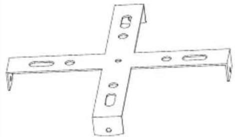 |  | 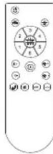 |
| Hanger bracket Remote control | ||
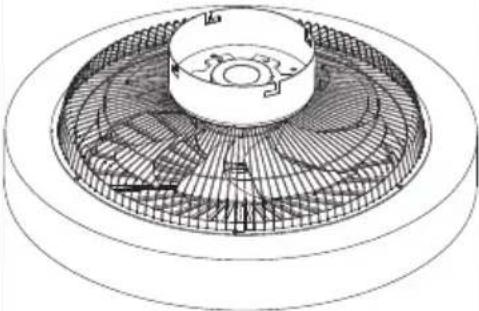 | 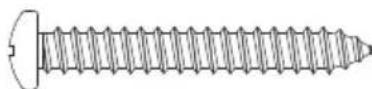  | |
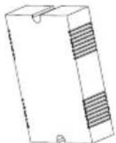
| Motor Spiral package | ||
- Open the packaging carefully. Remove the items from the Styrofoam inserts.
- Place the motor housing on a carpet or a piece of Styrofoam to avoid damaging the finish.
- Check the parts inventory to ensure that all parts have been included.
INSTALLATION
Installation Preparation
To prevent personal injury and damage, ensure that the hanging location allows the blades to be 2.3 m from the floor and 76 cm from any wall or obstruction. Ensure that the junction box is securely attached to the building structure and can support the full weight of the fan.
Installation requires these tools
Screwdriver, flat head screwdriver, adjustable pliers or wrench, stepladder, wire cutters and electrical tape.
Preparing the fan site
Downrod installation
This fan can be mounted on a normal or vaulted ceiling using a down rod. The hanging length can be increased by using a longer down rod.
Installing the hanger bracket
natural_image
Technical line drawing of a mechanical fan assembly with a hand holding a tool, showing internal components and motion direction (no text or symbols)Remove the side lock hanger screws and remove the hanger.
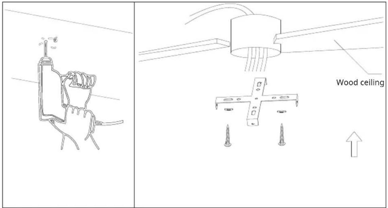
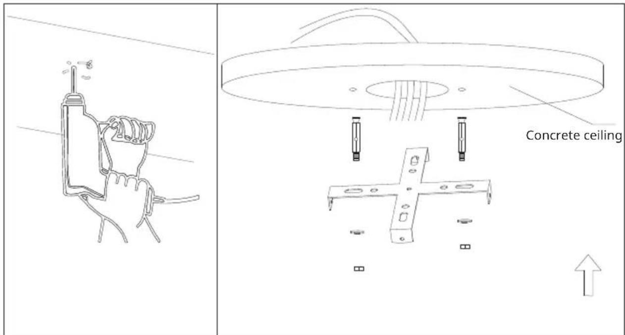
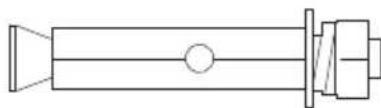
Please drill an 8 mm hole in the concrete ceiling and insert the bolt. Align the bracket with the hole and tighten it with the nut.
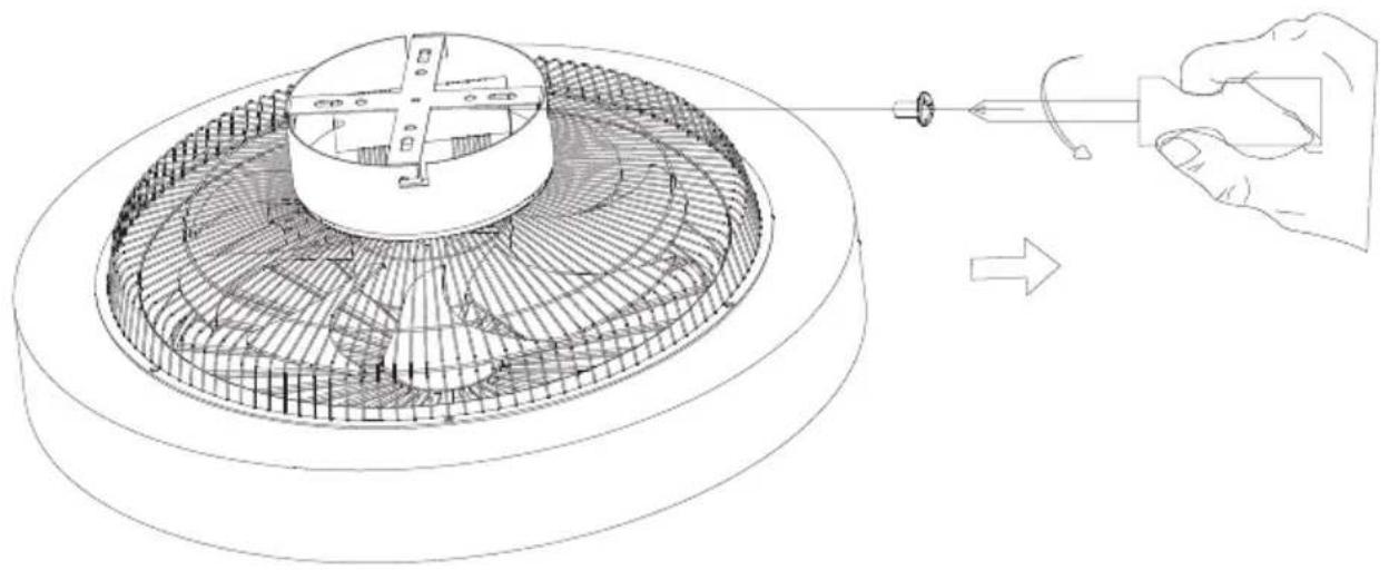
SECURING THE FAN
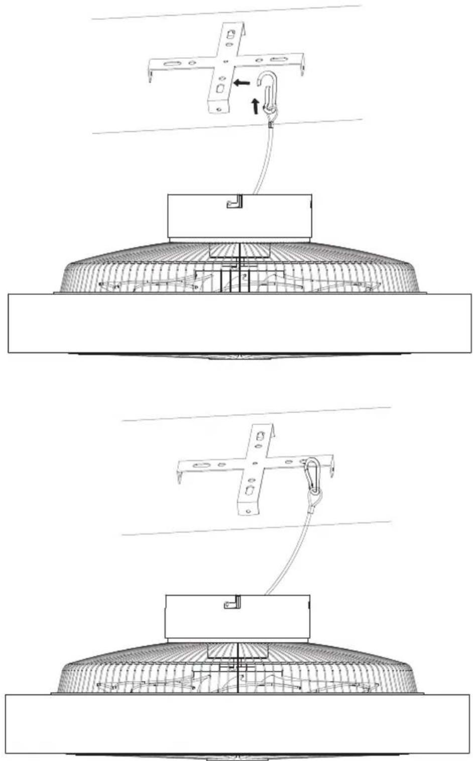
Steel wire rope suspension hanger for stabilizing the fan and saftey protection.
REMOTE CONTROL CONNECTION
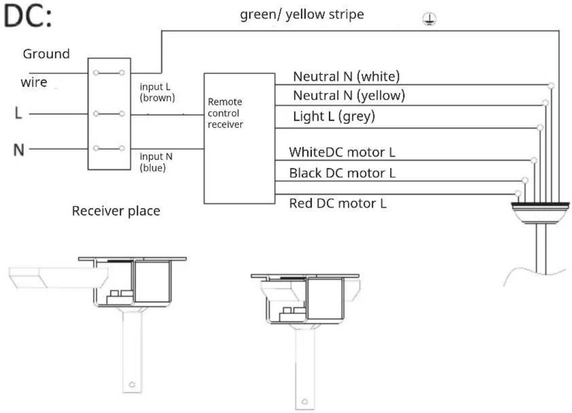
Canopy assembly
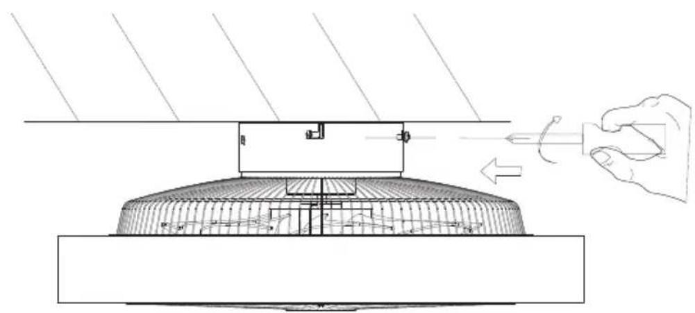
natural_image
Technical line drawing of a mechanical assembly with a hand holding a tool, showing internal components and motion arrows (no text or symbols)Lock the screws to secure the ceiling fan in place.
DEVICE CONTROL BY SMARTPHONE
If you integrate the device into your home WiFi, you can conveniently operate it via the associated Klarstein app. The app not only allows you to remotely control the device via your smartphone, but also gives you access to recipes and additional information.
Follow these steps to connect your smartphone to your Klarstein device:
- Download the Klarstein app first by scanning the QR code with your smartphone (see below), or download it directly from App Store or Google Play.
- Make sure your smartphone is connected to the same WiFi network that your Klarstein device is to be connected to.
- Open the Klarstein app.
- Sign in to your account. If you do not have an account, sign up in the Klarstein app.
- Follow the instructions from the app.
App Download
Use the scan function of your smartphone to scan the QR code and save the app on your smartphone.
Note: the app provides further information on how to use the app and help on how to connect to your device as soon as you open it for the first time.
| iOS Android | |
 |  |
Troubleshooting connection problems
If your Klarstein device cannot be found in the WiFi, check the following:
- The device is not plugged in. Make sure that your device is plugged into an electric socket.
- The device is not in pairing mode. Make sure that the WiFi indicator (LED) on the smart device control panel is blinking as described in the 'Reset WiFi settings' instruction of your smart device (instructions are usually available on device connection process).
- The WiFi access point does not operate on 5 GHz. Make sure that your access point operates on 2.4 GHz band and you have a separate SSID on 2.4 GHz band. If you are not sure about the operating band of your access point, please contact your internet provider company.
Important: please note that if your WiFi router is dual band - operating on both 2.4 GHz and 5 GHz band - you need to separate the SSIDs for each band and use the 2.4 GHz SSID for connection.
-
Firewall settings of your WiFi network; the firewall setting of your WiFi network may not allow the Klarstein app to configure the WiFi settings on your smart device. Please make sure that you are not using a public WiFi network, e.g. airports, dormitories, companies, etc.
-
Different credentials used in smartphone and the app. Make sure that the WiFi credentials entered in the Klarstein app are the same as the ones that your smartphone is connected to.
Following the above mentioned points, if your smart device still fails to connect to the app, please contact us via email for support: appsupport@klarstein.com
CLEANING AND CARE
• Always disconnect the appliance from the power supply before cleaning the appliance or carrying out maintenance work.
- Never use a wet sponge to clean the appliance.
- In order not to damage the product, it is advisable to use equipment adapted to the sensitive surfaces and products, which will slow down the wear of the device.
TROUBLESHOOTING
| Problem Possible | cause Approach | |
| The fan does not start. | Fuse or circuit breaker blown. | Check your fuses. |
| Loose cable connections. Check all connections for loose cables. | ||
| Speed was not set correctly. Select a speed. | ||
| The fan makes noise. | The upper cap touches the ceiling. | Make sure there is a minimum distance of 3 mm between the top cap and the ceiling. |
| Screws of rotor blades are loose. | Tighten all screws. | |
| Ceiling fan is not properly attached to the ceiling. | Tighten all screws in the suspension plate. | |
| Speed is not adjusted correctly. | Select a speed. | |
| The fan is wobbling. | Rotor blades are not adjusted horizontally to the ceiling. | Move the fan so that all blades are at the same height to the ceiling. |
| Screws of the rotor blades are loose. | Tighten all screws. | |
DATA SHEET
| Product information requirements according to REGULATION (EU) No 206/2012 | |||
| Information to identify the model(s) to which the information relates to | |||
| 10048235, 10048236 Zen Breeze | |||
| Description Symbol Value Unit | |||
| Maximum fan flow rate F 37.3 m3/min | |||
| Fan power input P 16.4 W | |||
| Service value SV 2.3 (m3/min)/W | |||
| Standby power consumption PSB 0.5 W | |||
| Fan sound power level LWA 53 dB(A) | |||
| Maximum air velocity | c | 1.8 m/s | |
| Measurement standard for service value | IEC 60879:2019 | ||
| Contact details for obtaining more information | Chal-Tec GmbHMühlenstraße 2510243 BerlinDeutschland | ||
DISPOSAL CONSIDERATIONS
natural_image
Symbol of a trash bin with crossed lines indicating no waste or discharge, accompanied by a solid black rectangle below (no text or labels)If there is a legal regulation for the disposal of electrical and electronic devices in your country, this symbol on the product or on the packaging indicates that this product must not be disposed of with household waste. Instead, it must be taken to a collection point for the recycling of electrical and electronic equipment. By disposing of it in accordance with the rules, you are protecting the environment and the health of your fellow human beings from negative consequences. For information about the recycling and disposal of this product, please contact your local authority or your household waste disposal service.
This product contains batteries. If there is a legal regulation for the disposal of batteries in your country, the batteries must not be disposed of with household waste. Find out about local regulations for disposing of batteries. By disposing of them in accordance with the rules, you are protecting the environment and the health of your fellow human beings from negative consequences.
DECLARATION OF CONFORMITY
Manufacturer & Importer for Great Britain:
Chal-Tec GmbH, Mühlenstraße 25, 10243 Berlin, Germany.
Contact: info@electronic-star.de
Hereby, Chal-Tec GmbH declares that the radio equipment type Zen Breeze in compliance with Directive 2014/53/EU. The full text of the EU declaration of conformity is available at the following internet address: use.berlin/10048235
For Great Britain: Hereby, Chal-Tec GmbH declares that the radio equipment type Zen Breeze is in compliance with the relevant statutory requirements. The full text of the declaration of conformity is available at the following internet address: use.berlin/10048235
Estimado cliente:
ÍNDICE
natural_image
Technical line drawing of a mechanical component with internal structure and tool, showing assembly or assembly process (no text or symbols)natural_image
Technical line drawing of a mechanical assembly with a hand holding a tool, showing internal components and motion arrows (no text or symbols)natural_image
Symbol of a trash bin with crossed x and y axes, no text or labels presentSOMMAIRE
natural_image
Technical line drawing of a mechanical component with internal structure and tool, showing assembly or assembly process (no text or symbols)natural_image
Technical line drawing of a mechanical assembly with a hand holding a tool, showing internal components and motion arrows (no text or symbols)natural_image
Simple line drawing of a trash bin with crossed x and y axes, no text or symbols presentDÉCLARATION DE CONFORMITÉ
Fabricant :
INDICE
natural_image
Technical line drawing of a mechanical component with internal structure and tool, showing assembly or assembly process (no text or symbols)natural_image
Technical line drawing of a mechanical assembly with a hand holding a tool, showing internal components and motion arrows (no text or symbols)natural_image
Symbol of a trash bin with crossed lines indicating no waste or discharge (no text or labels)
- CONTENTS
- TECHNICAL DATA
- SAFETY INSTRUCTIONS
- SCOPE OF DELIVERY
- INSTALLATION
- Installation Preparation
- Installation requires these tools
- Preparing the fan site
- Downrod installation
- SECURING THE FAN
- REMOTE CONTROL CONNECTION
- DEVICE CONTROL BY SMARTPHONE
- Follow these steps to connect your smartphone to your Klarstein device:
- App Download
- Troubleshooting connection problems
- CLEANING AND CARE
- DATA SHEET
- DISPOSAL CONSIDERATIONS
- DECLARATION OF CONFORMITY
- Estimado cliente:
- ÍNDICE
- SOMMAIRE
- DÉCLARATION DE CONFORMITÉ
- Fabricant :
- INDICE
Brand : Klarstein
Model : ZenBreeze Smart
Category : Fan