
Fiji Flow Smart - Fan Klarstein - Free user manual and instructions
Find the device manual for free Fiji Flow Smart Klarstein in PDF.

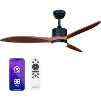
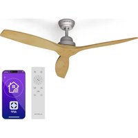
| Product type | Ceiling fan with LED light |
| Brand | Klarstein |
| Model | Fiji Flow Smart |
| Power supply | 220-240 V~ 50/60 Hz |
| WiFi frequency | 2.4–2.438 GHz |
| Maximum transmission power | 10 dBm |
| Control | Remote control and smartphone app (iOS/Android) |
| Lighting | Integrated LED |
| Number of blades | 4 |
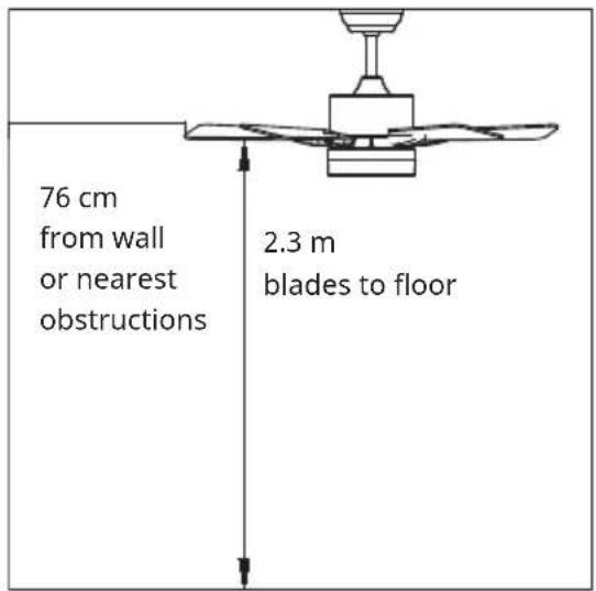
| Minimum distance from floor | 2.3 m |
| Minimum distance from walls | 76 cm |
| Minimum hook load capacity | 100 kg |
| Grounding | Required |
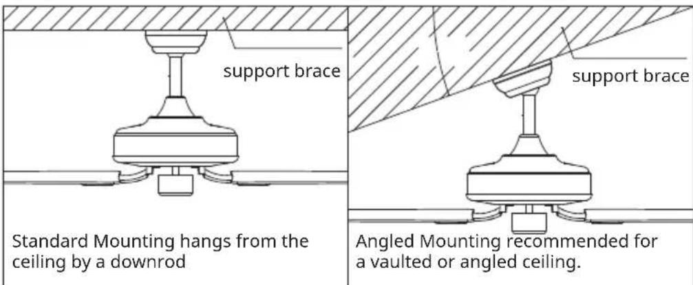
| Ceiling compatibility | Ordinary or sloped ceiling |
| Downrod | 6 inches (extendable with longer downrod) |
| Remote control batteries | 2 AAA batteries (not included) |
| Blade material | Not specified |
| Dimensions | Not specified |
| Weight | Not specified |
| Maintenance | Clean with a soft, dry cloth. Do not use abrasive products. |
| Recycling | Do not dispose of with household waste. Take to a collection point. |
| Warranty | See manufacturer's terms |
Frequently Asked Questions - Fiji Flow Smart Klarstein
User questions about Fiji Flow Smart Klarstein
0 question about this device. Answer the ones you know or ask your own.
Ask a new question about this device
Download the instructions for your Fan in PDF format for free! Find your manual Fiji Flow Smart - Klarstein and take your electronic device back in hand. On this page are published all the documents necessary for the use of your device. Fiji Flow Smart by Klarstein.
USER MANUAL Fiji Flow Smart Klarstein
INHALT
Technische Daten 3
natural_image
Technical line drawing of a mechanical device with a bowl and mounting bracket (no text or symbols)
natural_image
Technical line drawing of a mechanical component with no visible text or symbols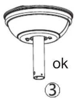
natural_image
Symbol of a trash bin crossed with a diagonal line, no text or numbers presentBerlin Brands Group UK Limited
PO Box 42
272 Kensington High Street
London, W8 6ND
United Kingdom
Congratulations on purchasing this equipment. Please read this manual carefully and take care of the following hints on installation and use to avoid technical damages. Any failure caused by ignoring the items and cautions mentioned in the operation and installation instructions are not covered by our warranty and any liability. Scan the QR code to get access to the latest user manual and more product information.

CONTENTS
Technical Data 19
Safety Instructions 20
Scope of Supply 21
Installaton 22
Use and Operation 28
Device Control by Smartphone 30
Disposal Considerations 32
Declaration of Conformity 32
TECHNICAL DATA
| Article number 10046091, 10046092 | |
| Power supply 220-240 V~ 50-60 Hz | |
| BTFrequency bandmaximum radio-frequency power | 2.4–2.438 GHz10 dBm |
SAFETY INSTRUCTIONS
- Never attach the fan to a power point, but to the ceiling itself.
- The minimum distance between the blades of the fan and the floor must be more than 2.3 m. The minimum carrying capacity of the hook from which the fan is hung must be 100 kg.
- Make sure to install all poles disconnection switch having a contact separation of at least 3 mm between poles in the supply wiring to the ceiling fan.
- The model or type reference of luminaries which may be installed in fans which are constructed for his purpose.
- Switch off the power before connecting.
- The electrical wiring must be in accordance with the local regulation.
- The fan must be properly earthed to avoid the risk of electric shocks.
- Never mount the fan in a moist or wet room.
- Be careful when working near the rotor blades.
Note: Always have your fan installed by someone who is knowledgeable about electrical wiring.
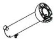
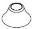
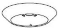
SCOPE OF SUPPLY
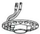
Carefully open the packaging. Remove items from Styrofoam inserts. Remove motor housing and place on carpet or Styrofoam to avoid damage to finish. Check against parts inventory that all parts have been included.
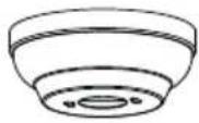 |  | 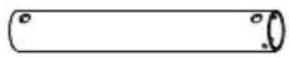 |
| canopy | downrod and hanging ball | downrod |
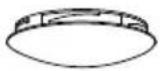
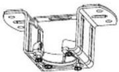 |  | 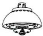 |
| hanger bracket | decorative covers | motor |
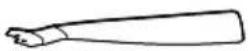 |  |  |
| blade | lamp panel | glass shade |
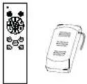 | 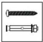 |  |
| remote control screw and dowel LED | ||
INSTALLATON
Installation prepraton
To prevent personal injury and damage, ensure that the hanging location allows the blades a clearance of 2.3m from the floor and 76cm from any wall or obstruction.
Be sure the outlet box is securely attached to the building structure and can support the full weight of the fan.
Preparing the Fan Site
Downrod Installation
This fan can be mounted with a downdrod on a normal or vaulted ceiling. The hanging length can be extended by a longer downdrod.
Installation requires these tools: Screwdriver, flat-head screwdriver, adjustable pliers or wrench, stepladder, wire cutters, and rated electrical tape.
Installing the Hanger Bracket
wood ceiling
concrete ceiling
Please drill 8 -mm hole on the concrete ceiling, and insert the the dowels and the bolts.
Align bracket with the hole, then tighten with nut.
Assembling and Hanging the Fan
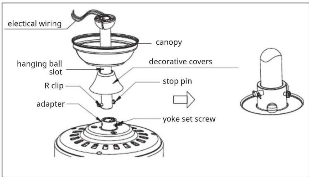
If you wish to extend the hanging length of your fan, you must remove the hanging ball from the 6 inch downrod provided to use with an extended downrod (included). (If you wish to use the 6 inch downrod, please proceed to instructions below.)
To remove hanging ball, loose set screw on hanging ball and remove pin and clip. Lower hanging ball and remove stop pin. Slide hanging ball off the original downrod A, and slide it down the longer downrod B (the top of the downrod should be noted as having a set screw hole; use this hole when setting the set screw).
Insert stop pin into top of extended downrod and raise hanging ball.
Be sure stop pin aligns with slots on the inside of the hanging ball, tighten set screw securely.
Tip: To prepare for threading electrical wires through downrod, apply small piece of electrical tape to the ends of electrical wires—this will keep the wires together when threading them through the downrod.
Loosen yoke set screws and nut at top of motor housing. Remove pin and clip from downrod (if you have not already done so). Slide downrod through canopy.
Tread electrical wires through downrod and pull extra wire slack from the upper end of the downrod.
Place downrod into the motor housing yoke. Insert the stop pin and clip that were previously removed. Tighten yoke set screws and nut securely. Lower the canopy to motor housing.
Remote control connection
DC:
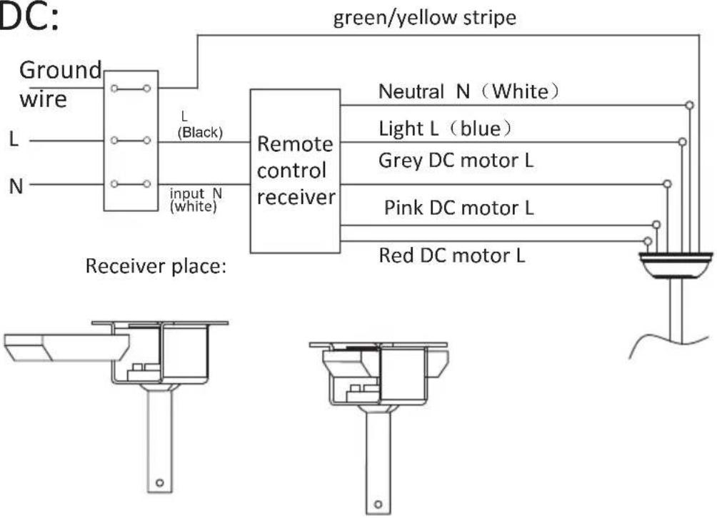
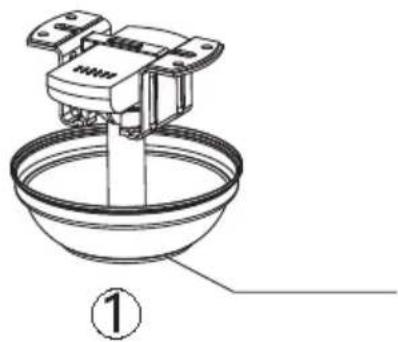
Canopy assembly
natural_image
Technical line drawing of a mechanical device with a base and housing, labeled with number 1 (no text or symbols on the diagram itself)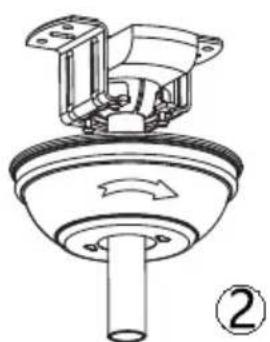
natural_image
Technical line drawing of a mechanical component with no visible text or symbols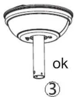
Raise canopy to hanging bracket, aligning loosened screws in hanging bracket with slotted holes in canopy. Twist canopy to lock. Re-insert screws and secured all screws with screwdriver.
With hanging bracket secured to the outlet box and able to support to fan, you are now ready to hang your fan. Grab the fan firmly with two hands. Slide downrod through opening in hanging bracket and let hanging ball rest on the hanging bracket. Turn the hanging ball slot until it lines up with the hanging bracket tab.
Tip: Seek the help of another person to hold the stepladder in place and to lift the fan up to you once you are set on the ladder.
Blade assembly
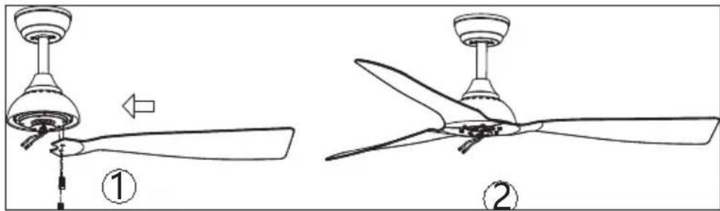
Time Saver: Washers for blade screws can be set on each blade screw prior to installing blades.
Located blade attachment screws and washer in one of the hardware packs. Hold blade arm up to the blade and align holes. Insert blade attachment screws (along with washers) with fingers first and then tighten screws securely with a screwdriver. Repeat for the remaining blades.
Remove blade arm screws and lock washers from underside of motor. If plastic motor locks are installed with blade arm screws, discard plastic motor locks (save blade arm screws and lock washers to secure blade arms). Align blade arm holes with motor screw holes and attach blade arm with lock washer and blade arm screws. Before securing screws permanently, repeat with remaining blade arms. Securely tighten all screws.
Note: Tighten blade arm screws twice
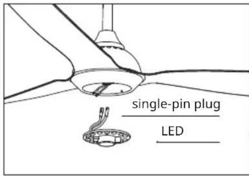
LED pan assembly
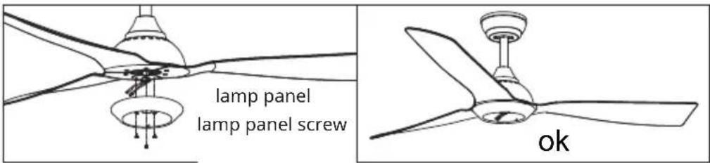
Unscrew a set screw. Attach the LED pan up to the bottom of the fan by inserting the other two set screw heads into key hole slots, rotate it to place, then secure the previous set screw by aligning screw hole and the hole at the bottom of the fan, tighten the rest two set screw to secure LED pan.
NOTE: While install or remove the LED pan, please keep the insulation pads intact carefully. Turning the set screws over-tightly or fast will damage the insulation pads.
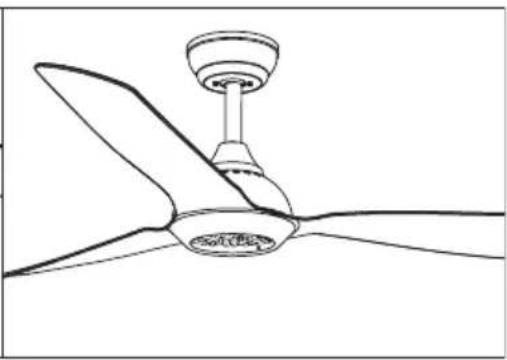
Lamp shade assembly
natural_image
Line drawing of a three-blade propeller with a central hub and top-mounted fan (no text or symbols)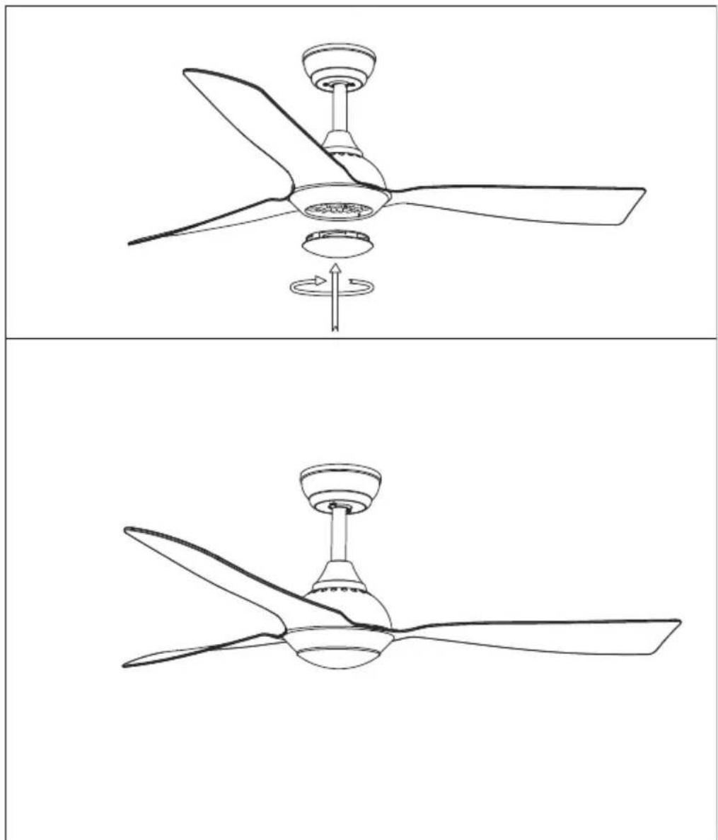
natural_image
Line drawings of a three-blade ceiling fan with a rotating knob, shown from top and side views (no text or symbols)Restore the cover and the lamp shade back to the LED pan, and secure them with decorative clips and bolt nuts.
USE AND OPERATION
Battery replacement
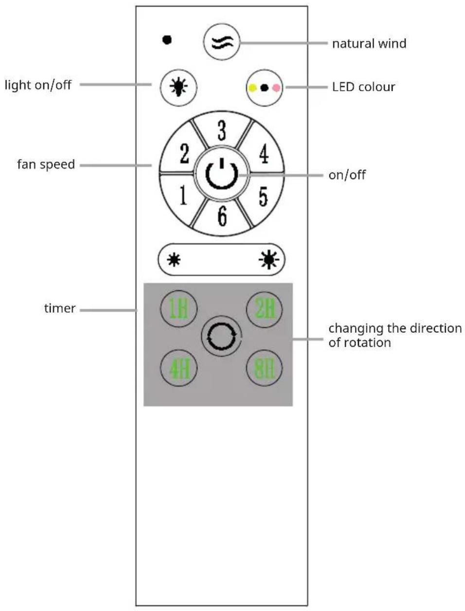
- Use the remote control transmitter to change the speed of the fan and to switch the light and fan on or off.
- Replace the batteries by sliding the battery compartment cover on the remote control transmitter in the direction of the arrow, fit 2 x "AAA" batteries, ensure the polarity of the batteries match with the figures shown in the battery compartment. (Note: Batteries NOT included). Re-assemble the battery compartment cover.
- ALWAYS ensure the battery compartment cover is closed properly. DO NOT expose the remote control to direct sunlight.
- DO NOT attempt to recharge expired batteries. There are special rechargeable batteries, which are clearly marked with. DO NOT dispose of batteries in fire to avoid explosion.
DEVICE CONTROL BY SMARTPHONE
If you integrate the device into your home WiFi, you can conveniently operate it via the associated Klarstein app. The app not only allows you to remotely control the device via your smartphone, but also gives you access to recipes and additional information.
Follow these steps to connect your smartphone to your Klarstein device:
1 Download the Klarstein app first by scanning the QR code with your smartphone (see below), or download it directly from App Store or Google Play.
2 Make sure your smartphone is connected to the same WiFi network that your Klarstein device is to be connected to.
3 Open the Klarstein app.
4 Sign in to your account. If you do not have an account, sign up in the Klarstein app.
5 Follow the instructions from the app.
App Download
Use the scan function of your smartphone to scan the QR code and save the app on your smartphone.
Note: The app provides further information on how to use the app and help on how to connect to your device as soon as you open it for the first time.
| iOS Android | |
 |  |
Troubleshooting connection problems
If your Klarstein device cannot be found in the WLAN, check the following:
1 The device is not plugged in. Make sure that your device is plugged into an electric socket.
2 The device is not in pairing mode. Make sure that the WiFi indicator (LED) on the smart device control panel is blinking as described in the 'Reset WiFi settings' instruction of your smart device (instructions are usually available on device connection process).
3 The WiFi access point does not operate on 2.4 GHz. Make sure that your access point operates on 2.4 GHz band and you have a separate SSID on 2.4 GHz band. If you are not sure about the operating band of your access point, please contact your internet provider company.
Important: please note that if your WiFi router is dual band - operating on both 2.4 GHz and 5 GHz band - you need to separate the SSIDs for each band and use the 2.4 GHz SSID for connection.
4 Firewall settings of your WiFi network; the firewall setting of your WiFi network may not allow the Klarstein app to configure the WiFi settings on your smart device. Please make sure that you are not using a public WiFi network, e.g. airports, dormitories, companies, etc.
5 Different credentials used in smartphone and the app. Make sure that the WiFi credentials entered in the Klarstein app are the same as the ones that your smartphone is connected to.
Following the above mentioned points, if your smart device still fails to connect to the app, please contact us via email for support: appsupport@go-bbg.com
DISPOSAL CONSIDERATIONS
natural_image
Symbol of a trash bin crossed with a diagonal line, no text or numbers presentIf there is a legal regulation for the disposal of electrical and electronic devices in your country, this symbol on the product or on the packaging indicates that this product must not be disposed of with household waste. Instead, it must be taken to a collection point for the recycling of electrical and electronic equipment. By disposing of it in accordance with the rules, you are protecting the environment and the health of your fellow human beings from negative consequences. For information about the recycling and disposal of this product, please contact your local authority or your household waste disposal service.
This product contains batteries. If there is a legal regulation for the disposal of batteries in your country, the batteries must not be disposed of with household waste. Find out about local regulations for disposing of batteries. By disposing of them in accordance with the rules, you are protecting the environment and the health of your fellow human beings from negative consequences.
DECLARATION OF CONFORMITY

Manufacturer:
Chal-Tec GmbH, Wallstrasse 16, 10179 Berlin, Germany.
Importer for Great Britain:
Berlin Brands Group UK Limited
PO Box 42
272 Kensington High Street
London, W8 6ND
United Kingdom
Hereby, Chal-Tec GmbH declares that the radio equipment type Fiji Flow Smart is in compliance with Directive 2014/53/EU. The full text of the EU declaration of conformity is available at the following internet address: use.berlin/10046091
For Great Britain: Hereby, Chal-Tec GmbH declares that the radio equipment type Fiji Flow Smart is in compliance with the relevant statutory requirements. The full text of the declaration of conformity is available at the following internet address: use.berlin/10046091
Cher client, chère cliente,
SOMMAIRE
Fiche technique 33
natural_image
Technical line drawing of a mechanical device with a bowl and mounting bracket (no text or symbols)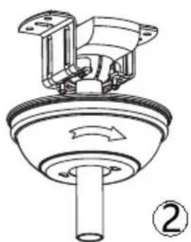
natural_image
Technical line drawing of a mechanical component with no visible text or symbols
natural_image
Line drawing of a three-blade flying fan with a central hub and rotating base (no text or symbols)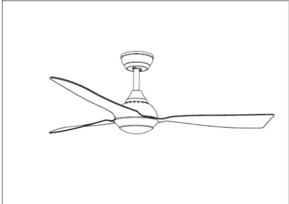
natural_image
Line drawing of a three-blade ceiling fan with a top-mounted head (no text or symbols)natural_image
Symbol of a trash bin crossed with a diagonal line, no text or numbers presentDÉCLARATION DE CONFORMITÉ

Fabricant :
Chal-Tec GmbH, Wallstraße 16, 10179 Berlin, Allemagne.
Berlin Brands Group UK Limited
PO Box 42
272 Kensington High Street
London, W8 6ND
United Kingdom
INDICE
Dati tecnici 47
natural_image
Technical line drawing of a mechanical device with a bowl and stand, labeled with number 1 (no text or symbols on the diagram itself)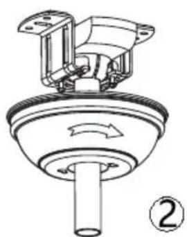
natural_image
Technical line drawing of a mechanical component with no visible text or symbols
natural_image
Diagram showing two views of a ceiling fan with labeled parts (① and ②), no text or symbols present.natural_image
Symbol of a trash bin crossed with a diagonal line, no text or numbers presentBerlin Brands Group UK Limited
PO Box 42
272 Kensington High Street
London, W8 6ND
United Kingdom
CONTENIDO
Datos técnicos 61
natural_image
Symbol of a trash bin crossed with a diagonal line, representing no waste or discharge (no text or labels)Berlin Brands Group UK Limited
PO Box 42
272 Kensington High Street
London, W8 6ND
Reino Unido

- INHALT
- CONTENTS
- TECHNICAL DATA
- SAFETY INSTRUCTIONS
- SCOPE OF SUPPLY
- INSTALLATON
- Installation prepraton
- Preparing the Fan Site
- Downrod Installation
- Assembling and Hanging the Fan
- Remote control connection
- Canopy assembly
- Blade assembly
- LED pan assembly
- Lamp shade assembly
- USE AND OPERATION
- Battery replacement
- DEVICE CONTROL BY SMARTPHONE
- App Download
- Troubleshooting connection problems
- DISPOSAL CONSIDERATIONS
- DECLARATION OF CONFORMITY
- Manufacturer:
- Importer for Great Britain:
- SOMMAIRE
- DÉCLARATION DE CONFORMITÉ
- Fabricant :
- INDICE
- CONTENIDO
Brand : Klarstein
Model : Fiji Flow Smart
Category : Fan