
TS 350 E - Chain saw HUSQVARNA - Free user manual and instructions
Find the device manual for free TS 350 E HUSQVARNA in PDF.
| Product type | Diamond disc cutter for cutting construction materials |
| Brand | Husqvarna |
| Model | TS 350 E |
| Use | Sawing marble, stone, granite, brick, cement, sandstone, tiles, ceramic |
| Disc diameter | 300 mm or 350 mm (bore 25.4 mm) |
| Disc rotation speed | 2800 rpm |
| Motor power | 2.2 kW (230 V), 2.9 kW (400 V), 1.5 kW (115 V) |
| Supply voltage | 230 V (single-phase), 400 V (three-phase) or 115 V (single-phase) depending on version |
| Rated current | 10 A (230 V), 11.5 A (400 V), 20 A (115 V) |
| Dimensions (L x W x H) | 1130 x 630 x 1300 mm (on legs); 1130 x 630 x 700 mm (workbench) |
| Total weight | Approximately 92 kg (chassis 56 kg, head 36 kg) |
| Cutting depth at 90° | 100 mm (disc 350) / 75 mm (disc 300) |
| Electrical protection | IP 54 |
| Cooling | Water spraying via integrated water pump (13 W, flow 8 l/min) |
| Water tank capacity | 40 liters minimum |
| Guaranteed sound power level | 112 dB(A) |
| Vibration level (handle) | 2.7 m/s² |
| Cutting functions | Straight and bevel cuts (0 to 45° left and right), depth adjustment |
| Safety | Lack-of-voltage switch, disc guard, requires 30 mA residual-current circuit breaker |
| Maintenance | Regular draining of the tank, cleaning of sliding surfaces, storage out of reach of children |
| Warranty | 12 months (defective parts, excluding wear) |
Frequently Asked Questions - TS 350 E HUSQVARNA
User questions about TS 350 E HUSQVARNA
0 question about this device. Answer the ones you know or ask your own.
Ask a new question about this device
Download the instructions for your Chain saw in PDF format for free! Find your manual TS 350 E - HUSQVARNA and take your electronic device back in hand. On this page are published all the documents necessary for the use of your device. TS 350 E by HUSQVARNA.
USER MANUAL TS 350 E HUSQVARNA
natural_image
Icon of an open book inside a circle (no text or symbols)FR Manuel d'utilisation - Lire attentivement et bien assimiler le manuel d'utilisation avant d'utiliser la machine.
Operator's manual - Please read the operator's manual carefully and make sure you understand the instructions before using the machine.
DE Bedienungsanweisung - Lesen Sie die Bedienungsanweisung sorgfältig durch und machen Sie sich mit dem Inhalt vertraut, bevor Sie das Gerät benutzen.
IT Istruzioni per l'uso - Prima di usare la macchina, leggere per intero le istruzioni per l'uso e accertarsi di averne compreso il contenuto.
ES Manual de instrucciones - Lea detenidamente el manual de instrucciones y asegúrese de entender su contenido antes de utilizar la máquina.
NL Gebruiksaanwijzing - Neem de gebruiksaanwijzing grondig door en gebruik de machine niet voor u alles duidelijk heeft begrepen.
SE Bruksanvisning - Läs igenom bruksanvisningen noggrant och förstå innehållet innan du använder maskinen.
Instruções para o uso - Leia as instruções para o uso com toda a atenção e compreenda o seu conteúdo antes de fazer uso da máquina.
TS 350 E
GB - Environmental Information
The symbol 📋 on the product or on its packaging indicates that this product may not be treated as household waste. Instead it shall be handed over to the applicable collection point for the recycling of electrical and electronic equipment. By ensuring this product is disposed of correctly, you will help prevent potential negative consequences for the environment and human health, which could otherwise be caused by inappropriate waste handling of this product. For more detailed information about recycling of this product, please contact your local council office, your household waste disposal service or the shop where you purchased the product.
FR - ASSURANCE DE CONFORMITÉ UE
GB - EC DECLARATION OF CONFORMITY
Husqvarna AB, SE-433 81 Göteborg, Sweden, tel: +46-31-949000, declares under sole responsibility that the Husqvarna TS 350 E dating from 2010 serial numbers and onwards (the year is clearly stated on the rating plate, followed by the serial number), complies with the requirements of the COUNCILiS DIRECTIVE:
• of May 17, 2006 "relating to machinery" 2006/42/EC
- of December 15, 2004 "relating to electromagnetic compatibility" 2004/108/EC.
- of December 12, 2006 "relating to electrical equipment" 2006/95/EC.
The following standards have been applied: EN ISO 12100:2003, EN 55014-1:2006, EN 55014-2/A1:2001, EN 61000-3-2:2006, EN 61000-3-11:2000, EN 12418/A1:2009.
Huskvarna December 29, 2009

Henric Andersson
Vice President,
Head of Power Cutters and Construction Equipment
(Authorized representative for Husqvarna AB and responsible for technical documentation.)
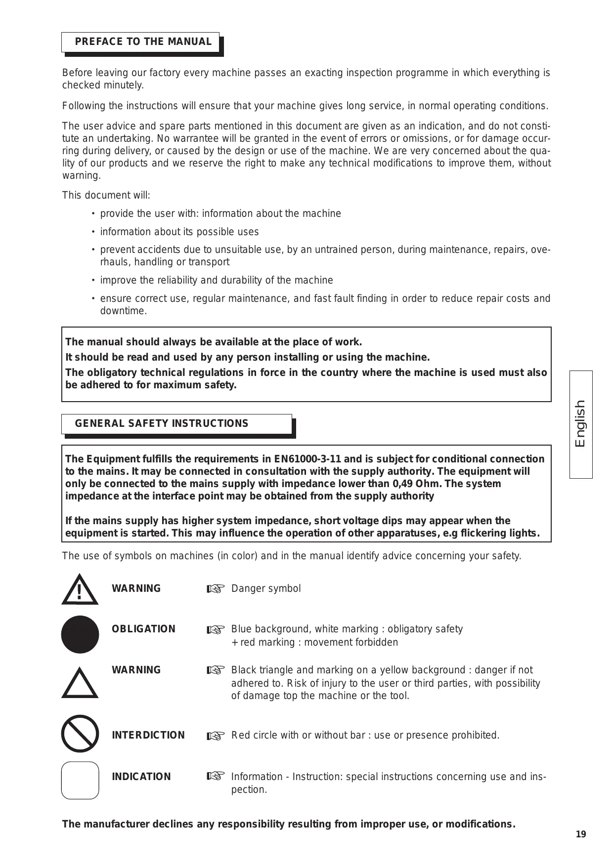
| Depth of cut (E) at 90°, mm | ∅ 350 = 100 | |
| ∅ 300 = 75 | ||
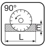
| Depth of cut (E) at 45°, mm | ∅ 350 = 60 | |
| ∅ 300 = 40 | ||
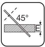
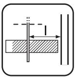
| Length of cut (L), mm | E = 15 - 650 | |
| E = 50 - 600 | ||
| Useable width (to the right) (l), mm | ∅ 350 = 310 | |
| ∅ 300 = 300 | ||
| Dimensions (mm) l x w x h | 1130 x 630 x 1300 (with legs) | |
| 1130 x 630 x 700 (bench) | ||
| Weight (depending on model), kg | ±92 | Chassis 56 |
| Head 36 | ||
| Disc cooling | Water spray into the disc casing | |
| Minimum tank capacity, l | 40 | |
| Water pump | 13 W - débit : 8 l/mn. | |
| Electricity supply | 230 V(H07-RNF 3 x 1,52 - Lg 3 m) | |
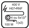
| 400 V(H07-RNF 4 ou 5 x 1,52 - Lg 3 m) | ||
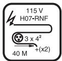
| 115 V(H07-RNF 3 x 2,52 - Lg 3 m) | ||
| Noise emissions (see note 1) | |
| Sound power level, measured dB(A) | 111 |
| Sound power level, guaranteed dB(A) | 112 |
| Sound levels (see note 2) | |
| Sound pressure level at the operators ear, dB(A) | 106 |
| Vibration levels, a_hv (see note 3) | |
| Handle, m/s ^2 | 2,7 |
Note 1: Noise emissions in the environment measured as sound power ( L_WA ) in conformity with EN 12418.
Note 2: Noise pressure level according to EN 12418. Reported data for noise pressure level has a typical statistical dispersion (standard deviation) of 1.0 dB(A).
Note 3: Vibration level according to EN 12418. Reported data for vibration level has a typical statistical dispersion (standard deviation) of 1 m/s^2 .
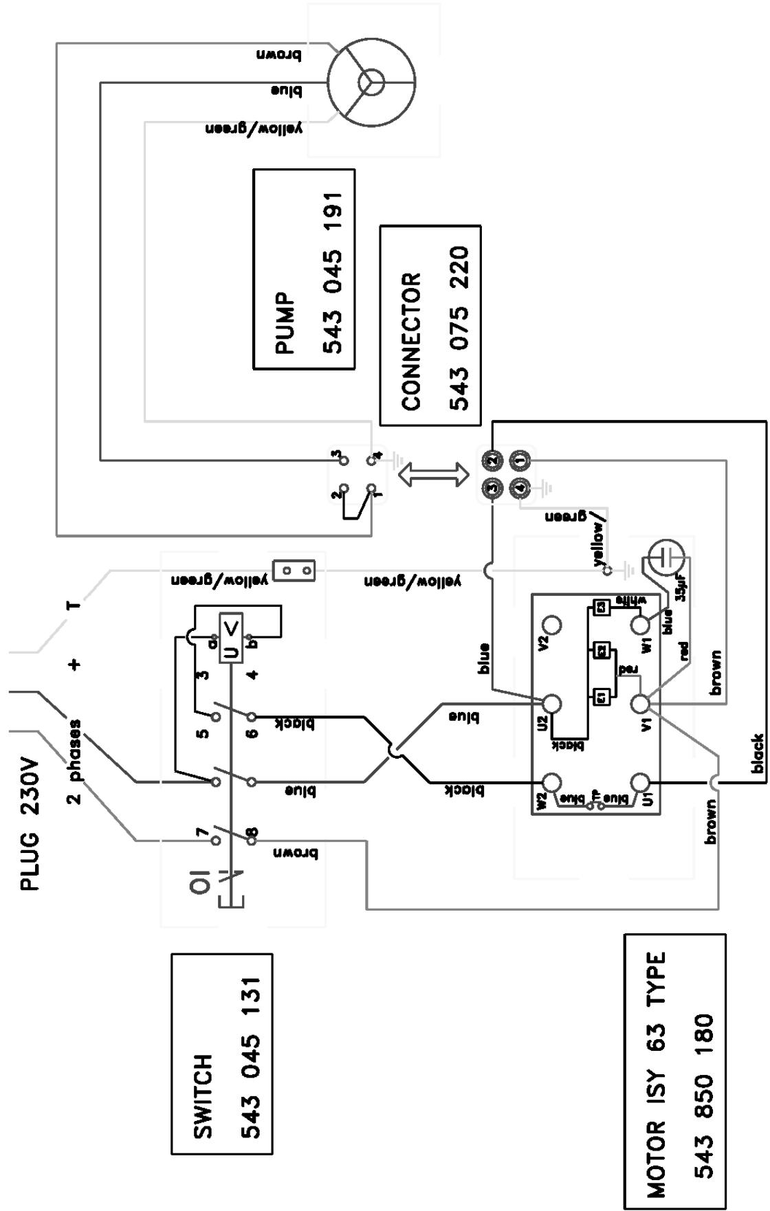
flowchart
graph TD
    A["SWITCH 543 045 131"] --> B["PLUG 230V"]
    B --> C["2 phases + T"]
    C --> D["O1 7"]
    D --> E["brown"]
    E --> F["blue"]
    F --> G["U <"]
    G --> H["black"]
    H --> I["yellow/green"]
    I --> J["PUMP 543 045 191"]
    J --> K["2"]
    K --> L["1"]
    L --> M["3"]
    M --> N["4"]
    N --> O["yellow/green"]
    O --> P["CONNECTOR 543 075 220"]
    P --> Q["3③②④①"]
    Q --> R["w2"]
    Q --> S["u2"]
    Q --> T["v2"]
    Q --> U["U1"]
    Q --> V["V1"]
    Q --> W["W1"]
    Q --> X["white"]
    X --> Y["yellow/"]
    Y --> Z["red"]
    Z --> AA["35μF"]
    AA --> AB["brown"]
    AB --> AC["brown"]
    AC --> AD["black"]
    AD --> AE["motor isy 63 TYPE 543 850 180"]
4 Manutention - Transport
Before leaving our factory every machine passes an exacting inspection programme in which everything is checked minutely.
Following the instructions will ensure that your machine gives long service, in normal operating conditions.
The user advice and spare parts mentioned in this document are given as an indication, and do not constitute an undertaking. No warrantee will be granted in the event of errors or omissions, or for damage occurring during delivery, or caused by the design or use of the machine. We are very concerned about the quality of our products and we reserve the right to make any technical modifications to improve them, without warning.
This document will:
• provide the user with: information about the machine
• information about its possible uses
- prevent accidents due to unsuitable use, by an untrained person, during maintenance, repairs, overhauls, handling or transport
- improve the reliability and durability of the machine
- ensure correct use, regular maintenance, and fast fault finding in order to reduce repair costs and downtime.
The manual should always be available at the place of work.
It should be read and used by any person installing or using the machine.
The obligatory technical regulations in force in the country where the machine is used must also be adhered to for maximum safety.
GENERAL SAFETY INSTRUCTIONS
The Equipment fulfills the requirements in EN61000-3-11 and is subject for conditional connection to the mains. It may be connected in consultation with the supply authority. The equipment will only be connected to the mains supply with impedance lower than 0,49 Ohm. The system impedance at the interface point may be obtained from the supply authority
If the mains supply has higher system impedance, short voltage dips may appear when the equipment is started. This may influence the operation of other apparatuses, e.g flickering lights.
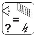
The use of symbols on machines (in color) and in the manual identify advice concerning your safety.

WARNING

Danger symbol

OBLIGATION

Blue background, white marking : obligatory safety
+ red marking : movement forbidden

WARNING

Black triangle and marking on a yellow background : danger if not adhered to. Risk of injury to the user or third parties, with possibility of damage top the machine or the tool.

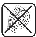
INTERDICTION

Red circle with or without bar : use or presence prohibited.

INDICATION

Information - Instruction: special instructions concerning use and inspection.

This symbol indicates that the machine is in conformance with the applicable European directive.
SPECIAL INSTRUCTIONS
The disc cutter is designed to provide safe and reliable service in operating conditions corresponding with the instructions, but it can present dangers for the user and risks of damage, consequently regular on site inspection is necessary to ensure :
- Perfect technical condition (use for the purpose for which it is intended and taking into account any risks, and correction of any malfunction detrimental to safety).
- Use of a diamond disc for water lubricated cutting of marble, stone, granite, brick and facings (porcelain, glazed tiles, ceramics, etc). The use of any other disc is forbidden (abrasive, saw, etc).
- Competent personnel (qualifications, age, training, education) who have studied the manual in detail before starting work: any fault of an electrical or other nature must be checked by a competent person (electrician, maintenance foreman, authorized dealer, etc).
- That the warnings and instructions marked on the machine are followed (adequate personal protection, correct use, general safety instructions, etc).
- That no modification, transformation or addition is detrimental to safety and that it is carried out without prior authorization from the manufacturer.
- Respect of the maintenance intervals and periodical checks recommended.
- That only genuine spare parts are used for repairs.
Instruction plate
1 Use
- Use : Sawing marble, stone, granite, brick, cement and all facings (porcelain, glazed tiles, ceramics, etc).
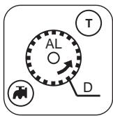
- Tools : Water lubricated diamond disc diameter 300 mm - diameter 350 mm (D)- bore 25.4 mm (AL). (Information from your usual supplier).
Carborundum disc

Saw blade
Any application not corresponding with the intended use (use of a saw blade, abrasive disc, etc) is prohibited.
3 Inspection-Description of the machine
- On receiving the machine check its condition.
• Always keep it perfectly clean. - Check the supply cable lead periodically.
• Always keep alert when working. - Check the mounting of the components (abnormal vibration).
SEE FIG. 1
① Chassis-tank
② Leg
③ Head clamping handle
④ Water pump
⑤ Lifting lever
⑥ Locking handle
⑦ Loading leg
⑧ Drain plug
⑨ Motor
⑩ Lack of voltage switch
⑪ Hood
⑫ Disc casing
⑬ Housing cover
⑭ Movable table
⑮ Table stop
⑯ Movable table stop
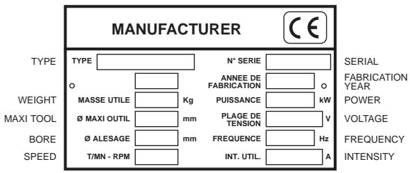
⑰ Manufacturer's plate
(18) Cutting guide
⑲ Table locking
20 Carrying handles
21 Transport wheels
22 Water tank
23 Water level
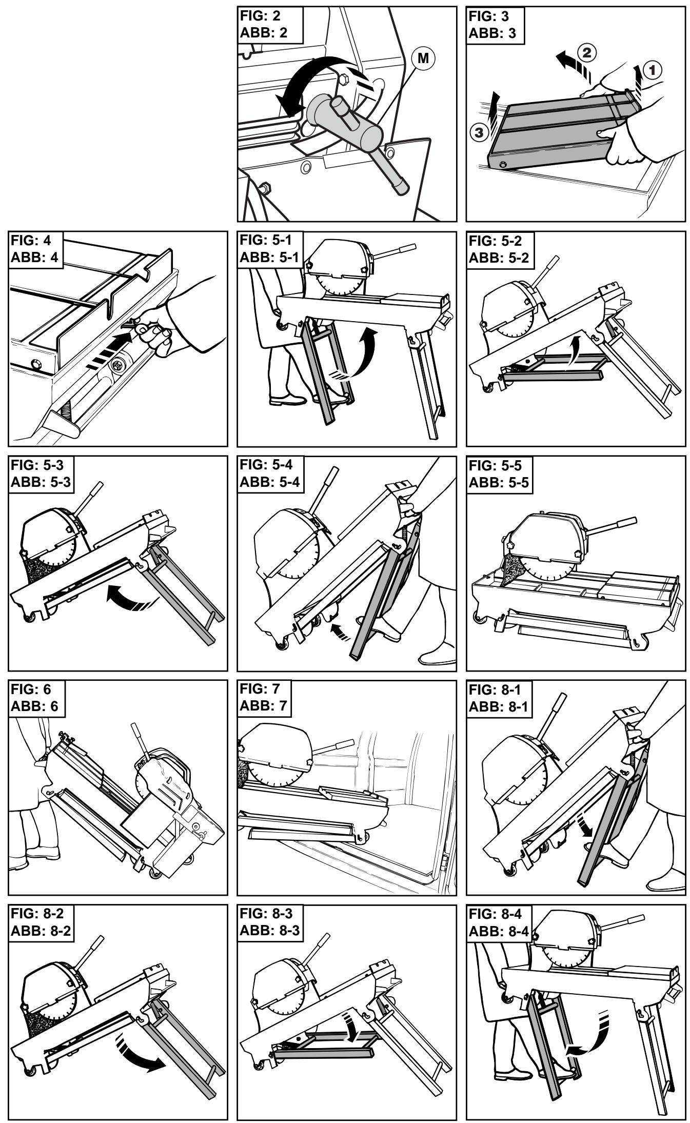
4 Handling - transport
Dismantle your machine into two parts.
TABLE PART (SEE FIG 3)
- Remove the table by tilting it slightly so as to clear the rear retainer pins
BLOCKING TABLE FOR TRANSPORTATION (SEE FIG 4)
FOLDING THE FEET (SEE FIG 5)
TRANSPORT (SEE FIG 6)
LOADING (SEE FIG 7)
PLACING ON FEET (SEE FIG 8)
5 Inspection before starting

Please read the instructions for use prior to operating the machine for the first time.

The use of ear protection is mandatory.


The operator must wear protective clothing appropriate to the work he is doing. We recommend that this includes both eye and ear protection.

The working area must be completely cleared, well lit and all safety hazards removed (no water or dangerous objects in the vicinity).

Any persons not involved in the work should leave the working area.
Use blades suitable for the work to be done (speed, geometry, application, etc.).
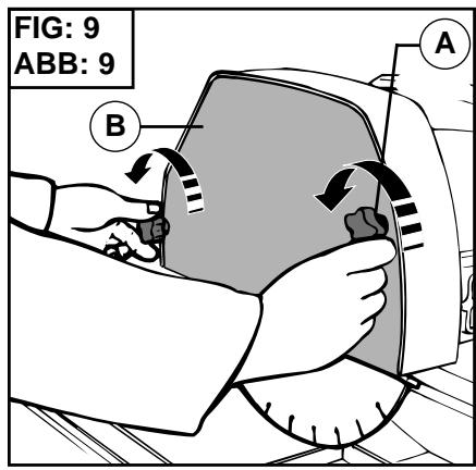
6 Fitting the disc

Disconnect the machine by unplugging the supply cable.
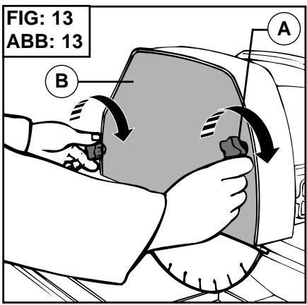
- Remove the two screw knobs (A) and the protective case (B) (SEE FIG 9).

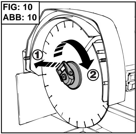
The disc locking nut has a left-hand thread.

If the machine is fitted with a brake motor, do not use the quick-tightening nut.
- Remove the locking flange (SEE FIG 10).
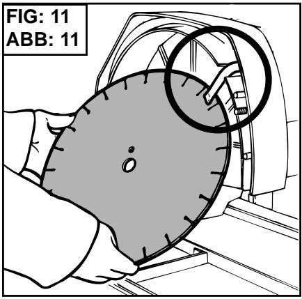
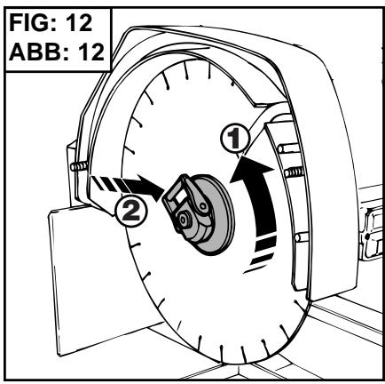
• Fit the disc.(SEE FIG 11).

Take care about the direction of rotation which is shown by an arrow on one of the faces.
Make sure the contact faces of flanges, of blade and the axle are clean.
- Tighten the nut (1) and lock (2)
- Refit the protective case (B).
- Tighten the 2 screw knobs (A) (SEE FIG 13)..
7 Electrical connection
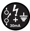
- ELECTRICAL SAFETY :
Operate this machine only on a supply equipped with a 30 mA earthed current-limiting circuit-breaker. Otherwise, consult our catalogue for appropriate models.
- The RCCB must be used correctly, including testing it regularly. For tools supplied with an integral RCCB in the cable or in the mains plug, if the cable or plug has been damaged, repairs must be carried out by the manufacturer, one of his agents or by a qualified repair workshop to avoid any risks resulting from errors.
- Make sure that the mains voltage corresponds with that marked on the manufacturer's plate on the machine.
- Three-phase motor
Make sure that the motor rotates in the same direction as the arrow stamped on the casing: if the motor does not turn in the direction required, swap two of the supply wires.
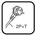
- Use the following types of plug, single phase 2 P + E, or 3 P + E / 3 P + N + E according to the corresponding voltage.
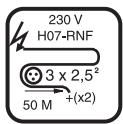
- Extension lead: Cable size sufficient for the electrical power, connection to the mains by a H07 RNF type cable of the following size:
- 3 x 2.5 mm ^4 up to 50 m for 230 V
- 4 or 5 x 1.5 mm ^2 up to 100 m for 400 V
- 3 x 4 mm ^2 up to 40 m for 115 V
8 Starting up
Always pay extreme care and attention to the preparation of the machine before starting up
Remove all adjustment tools and wrenches from floor and machine
Always keep blade guard in place
- Fill the water tank (level 23 FIG 1).
- The water pump starting is coupled with that of the motor.
As each machine is fitted with a self priming pump, the water is sprayed onto the disc as soon as the machine starts.
Ensure that the water supply is abundant, when cutting wet.
The protective case and the motor mounting fitted with a deflector blade provide perfect distribution of the spray.
- To start the machine press the green button on the switch (optional cut-out switch).

- To stop the machine, press the red button.
phase motor protected by a built-in thermal circuit breaker.
9 Cutting method
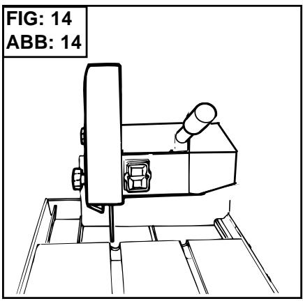
• Straight cuts (SEE FIG 14)
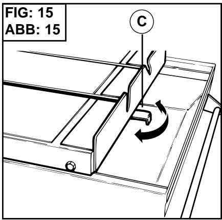
☐ 570 mm : the stop (C) prevents fingers being trapped between the table and the frame (SEE FIG 15).
♂ > 570 et 650 mm : retract the stop (C) under the table to increase the stroke.
A reversible and removable cutting guide enables 45^ to 90^ cuts to be made.
This cutting guide is machined in such a way that it can be fitted in several positions in addition to its right angle position from 0^ to 45^ to the left or to the right.
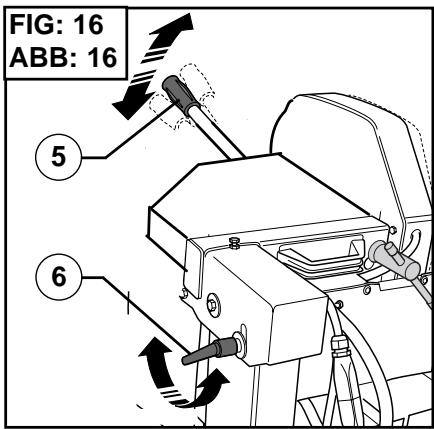
10 Depth of cut adjustment
(SEE FIG. 16).
- Slacken off handle (6).
- Use lever (5) to adjust the cutting height.
- Tighten handle (6).
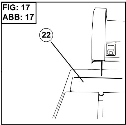
11 Maintenance (the motor must be stopped)
- Clean the machine regularly.
- Drain the tank (22) frequently to remove cutting residue, which otherwise could block the pump and cause it to wear out prematurely. (SEE FIG 17).
- Swill out the tanks (1) and (22) with water.
- Carefully clean the contact faces for the table rollers.

Store in a dry place, not accessible to children.
Maintain the tools carefully.
FAULT FINDING
In the event of faulty operation refer to the tables below to find a solution.
• The machine does not work
| CAUSES | REMEDIES |
| Not plugged in properly or cable damaged | - Make sure that the supply is correctly plugged in (plug, extension lead, etc)- Check the supply cable |
| No mains voltage | - Test or have tested by an electrician (circuit breaker, plug, etc) |
| Switch defective, motor cable damaged | - Have tested by an electrician or contact the service department |
| Motor faulty (no power, unpleasant smell) | - Contact the service department to have the motor replaced |
- Difficult starting
| CAUSES | REMEDIES |
| Single phase motor starting condenser | - Replace the condenser |
| Three-phase supply not correct (on 2 phases, motor cable faulty) | - Have it checked by an electrician or contact the service department |
• The pump does not start
| CAUSES | REMEDIES |
| The mains lead is not correctly connected or is damaged | - Check the mains lead |
| No voltage in pump circuit or mains supply circuit | - Check the pump circuit and mains supply circuit |
- The pump does not pump water
| CAUSES | REMEDIES |
| An air bubble may have formed inside the pump body | - Holding the pump of the outlet pipe remove it from the water and reimmerse it |
| The turbine is jammed | - Unscrew the filter and, using a small screwdriver, remove all dirt from the operating area of the turbine. |
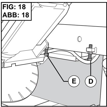
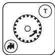
12 Adjustments
- The machine is set before leaving the factory and no adjustment is necessary.
- However, after shocks, loosening of nuts and bolts, or sharp movements when tilting the head, if necessary adjust the stop screws(D) and check the squareness (for straight cuts).
- To correct the bevel cutting setting, adjust the stop screw (E) and lock the nut with a lock- nut (SEE FIG. 18).
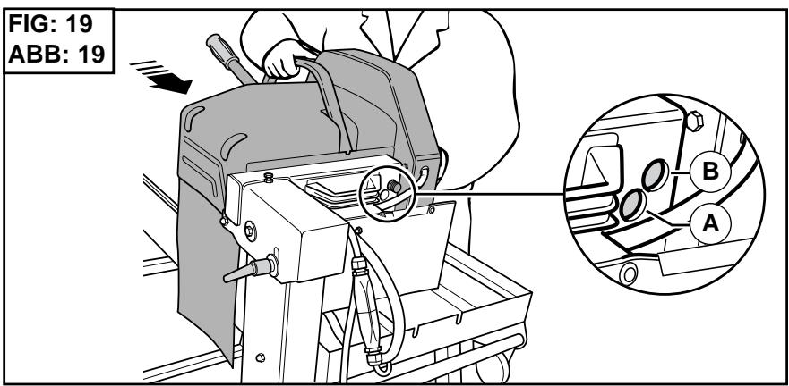
- ∅ 300 and ∅ 350 adaptation (SEE FIG. 19)
$$ \mathbf {A} = \varnothing 3 0 0 $$
$$ \mathbf {B} = \varnothing 3 5 0 $$
13 Important advice
- Retighten the nuts and bolts periodically.
- In the event of a long period of use pay special attention to the maintenance and protection of the disc.
- Make sure that sufficient water is sprayed onto the disc.
- Tighten the disc correctly.
- Make sure that the contact faces of the disc, the flanges and the spindle are clean.

The manufacturer declines all responsibility for loss or damage resulting from misuse or any modification, alteration or powering that does not conform to the manufacturer's original specifications.

At the work station, the sound pressure level may exceed 85 db (A) In this case individual protection measures must be taken.
14 Repairs
S A V
Contact your supplier who is entirely at your service to carry out repairs in the shortest time at the best possible price.
15 Spare parts
For rapid delivery of spares and in order to avoid any wasted time, it is necessary to remind your supplier of the details shown on the instruction plate on the machine with each order, as well as the reference of the part to be replaced.

flowchart
graph TD
    A["Item numberCode"] --> B["00000000"]
    B --> C["(0)"]
    C --> D["Quantity"]
See exploded view
16 Scrapping

In the event of deterioration and scrapping of the machine, the following items must be disposed of in accordance with the requirements of the legislation in force.
- Main materials :
■ Motor : Aluminium (AL), Steel (AC), Copper (CU), Polyamide (PA)
■ Machine : Steel sheet (AC), Cast iron (FT)
The instructions for use and spare parts found in this document are for information only and are not binding. As part of our product quality improvement policy, we reserve the right to make any and all technical modifications without prior notice.
Handhabung - Transport
flowchart
graph TD
    A["00000000"] --> B["Kod"]
    C["(0)"] --> D["Antal"]
Se sprängskissen
16 Avfallshantering

| WARRANTY CONDITIONS |
| 1. PERIODThe warranty is acknowledged as of the date of purchase (date of the invoice of the distributor) and is valid for a period of 12 months. |
| 2. WARRANTYThe warranty is limited to the free of charge replacement of parts recognised as defective by Husqvarna (excluding wear components and consumables) providing the repair is made within after-sales service of Husqvarna or a recognised Husqvarna repair centre. |
| The manufacturer is not responsible for any direct or indirect, material or immaterial, damages caused to persons or things by failure of the machine or the non operation of the machine. |
| 3. WARRANTY CONDITIONSTo benefit the warranty, it is necessary to return the joined warranty certificate, duly completed, to Husqvarna within eight days of the purchase.In case of failure of the machine during the warranty period, our after-sales services will inform you of the appropriate and most effective method of dealing with your claim and advise you if necessary of your nearest approved service centre.As an alternative, you may return, at your cost, the machine together with a written description of the problem and damages with a copy of the invoice directly to our after sales department where upon a full investigation will be instigated without delay. |
| 4, EXCLUSIONSWarranty will not be applied for damages or failures caused by:- incorrect use, error in transportation, handling or maintenance,- use of incorrect fuel or lubricants not advised by Husqvarna,- use of non-genuine parts or accessories,- repairs made by non approved service centres,- use of incorrect specifications of cutting tools. (We suggest the use of Husqvarna tools). |
| The goods are returned at the sole responsibility of the Buyer who must appeal against the transporter in the usual manner without delay. |
Español
Theorem 1.2. (A) Let f be a finite field and let g be the set of all elements of f . Then
Cloud's business, Maryland, and other services
Warranty certificate
- Certificat de garantie
• Garantie-Zertifikat
Place here CE sticker with serial N°
To benefit from the warranty, it is mandatory to return, within eight days after the purchase, the attached warranty certificate.
Warranty certificate
Certificat de garantie • Garantie-Zertitikat • Certificato di garanzia • Garantie bewijs • Certificado de garantia • Certificado de garantia • Garanticertifikat
Company :
Société • Gesellschaft • Societa • Maatchappij • Sociedade • sociedad • Företag
Address :
Adresse • Adresse • indirizzo • Adres • Endereco • Direccion • Adress
Date of Acquisition :
Date d'achat • Datum des Kaufs • Data di acquisto • Datum van aankoop • Data de compra • Fecha de comprar • Inköpsdatum
Machine Type :
Type de la machine • Maschinen Type • Tipo della macchina • Machine Type • Tipo de maquina • Tipo de maquina • Maskintyp