
FS 400 LV - Construction Equipment HUSQVARNA - Free user manual and instructions
Find the device manual for free FS 400 LV HUSQVARNA in PDF.

| Product type | Floor saw (concrete chainsaw) |
| Brand | HUSQVARNA |
| Model | FS 400 LV |
| Dimensions (L x W x H) | 1220 x 600 x 1000 mm |
| Nominal weight (empty) | 99 kg |
| Operating weight | 135 kg |
| Cutting depth | 125 / 140 / 165 mm |
| Spindle rotation speed | 2950 rpm (at 3700 rpm engine) |
| Compatible disc diameter | 350, 400 or 450 mm, bore 25.4 mm |
| Disc type | Wet diamond |
| Power supply | Petrol engine (400 V electric version available) |
| Sound power level | 107 dB(A) measured, 108 dB(A) guaranteed |
| Sound pressure level | 89 dB(A) |
| Vibrations right handle | 7.0 m/s² |
| Vibrations left handle | 9.2 m/s² |
| Water system | Water inlet tap, abundant watering recommended |
| Safety | Emergency stop, protective guard, DCDR for electric version |
| Maintenance | Grease spindle bearings every 8h, check engine oil daily, periodic belt tension |
| Warranty | 12 months from date of purchase |
| Spare parts | Original recommended, order with serial number |
Frequently Asked Questions - FS 400 LV HUSQVARNA
User questions about FS 400 LV HUSQVARNA
0 question about this device. Answer the ones you know or ask your own.
Ask a new question about this device
Download the instructions for your Construction Equipment in PDF format for free! Find your manual FS 400 LV - HUSQVARNA and take your electronic device back in hand. On this page are published all the documents necessary for the use of your device. FS 400 LV by HUSQVARNA.
USER MANUAL FS 400 LV HUSQVARNA
FR Manuel d'utilisation - Lire attentivement et bien assimiler le manuel d'utilisation avant d'utiliser la machine.
Operator's manual - Please read the operator's manual carefully and make sure you understand the instructions before using the machine.
DE Bedienungsanweisung - Lesen Sie die Bedienungsanweisung sorgfältig durch und machen Sie sich mit dem Inhalt vertraut, bevor Sie das Gerät benutzen.
IT Istruzioni per l'uso - Prima di usare la macchina, leggere per intero le istruzioni per l'uso e accertarsi di averne compreso il contenuto.
ES Manual de instrucciones - Lea detenidamente el manual de instrucciones y asegúrese de entender su contenido antes de utilizar la máquina.
NL Gebruiksaanwijzing - Neem de gebruiksaanwijzing grondig door en gebruik de machine niet voor u alles duidelijk heeft begrepen.
SE Bruksanvisning - Läs igenom bruksanvisningen noggrant och förstå innehållet innan du använder maskinen.
Instruções para o uso - Leia as instruções para o uso com toda a atenção e compreenda o seu conteúdo antes de fazer uso da máquina.
FS 400 LV
FR - CARACTÉRISTIQUES TECHNIQUES
FR - ASSURANCE DE CONFORMITÉ UE
| Depth of cut, mm | 125 / 140 / 165 |
| Nominal weight (empty), kg | 99 |
| Operating weight, kg | 135 |
| Dimensions (LxWxH), mm | 1220 x 600 x 1000 |
| Speed blade shaft, rpm(@ 3700 engine, rpm) | 2950 |
| Noise emissions (see note 1) | |
| Sound power level, measured dB(A) | 107 |
| Sound power level, guaranteed dB(A) | 108 |
| Sound levels (see note 2) | |
| Sound pressure level at the operators ear, dB(A) | 89 |
| Vibration levels, ahv (see note 3) | |
| Handle right, m/s 2 | 7,0 |
| Handle left, m/s 2 | 9,2 |
Note 1: Noise emissions in the environment measured as sound power ( LWA ) in conformity with EC directive 2000/14/EC.
Note 2: Noise pressure level according to EN 13862. Reported data for noise pressure level has a typical statistical dispersion (standard deviation) of 1.0 dB(A).
Note 3: Vibration level according to EN 13862. Reported data for vibration level has a typical statistical dispersion (standard deviation) of 1 m/s2 .
GB - EC DECLARATION OF CONFORMITY
Husqvarna AB, SE-433 81 Göteborg, Sweden, tel: +46-31-949000, declares under sole responsibility that the Husqvarna FS 400 LV dating from 2010 serial numbers and onwards (the year is clearly stated on the rating plate, followed by the serial number), complies with the requirements of the COUNCILiS DIRECTIVE:
• of May 17, 2006 "relating to machinery" 2006/42/EC
- of December 15, 2004 "relating to electromagnetic compatibility" 2004/108/EC.
- of May 8, 2000 "relating to the noise emissions in the environment" 2000/14/EC.
The following standards have been applied: EN ISO 12100:2003, EN 55014-1:2006, EN 55014-2/A1:2001,
EN 61000-3-2:2006, EN 61000-3-3/A1/A2:2005, EN 13862/A1:2009.
Huskvarna December 29, 2009

Henric Andersson
Vice President,
Head of Power Cutters and Construction Equipment
(Authorized representative for Husqvarna AB and responsible for technical documentation.)
Head of Power Cutters and Construction Equipment
GB - Environmental Information
The symbol 📁 on the product or on its packaging indicates that this product may not be treated as household waste. Instead it shall be handed over to the applicable collection point for the recycling of electrical and electronic equipment. By ensuring this product is disposed of correctly, you will help prevent potential negative consequences for the environment and human health, which could otherwise be caused by inappropriate waste handling of this product. For more detailed information about recycling of this product, please contact your local council office, your household waste disposal service or the shop where you purchased the product.
4 - MANUTENTION TRANSPORT
12 – RECOMMANDATIONS IMPORTANTES
Before leaving our factory every machine passes an exacting inspection programme in which everything is checked minutely.
Following the instructions will ensure that your machine gives long service, in normal operating conditions.
The user advice and spare parts mentioned in this document are given as an indication, and do not constitute an undertaking. No warrantee will be granted in the event of errors or omissions, or for damage occurring during delivery, or caused by the design or use of the machine. We are very concerned about the quality of our products and we reserve the right to make any technical modifications to improve them, without warning.
This document will:
• provide the user with: information about the machine
• information about its possible uses
- prevent accidents due to unsuitable use, by an untrained person, during maintenance, repairs, overhauls, handling or transport
- improve the reliability and durability of the machine
- ensure correct use, regular maintenance, and fast fault finding in order to reduce repair costs and downtime.
The manual should always be available at the place of work. It should be read and used by any person installing or using the machine.
The obligatory technical regulations in force in the country where the machine is used must also be adhered to for maximum safety.
GENERAL SAFETY INSTRUCTIONS
The use of symbols on machines (in color) and in the manual identify advice concerning your safety.

WARNING
Danger symbol

OBLIGATION
Blue background, white marking : obligatory safety
+ red marking : movement forbidden

WARNING
Black triangle and marking on a yellow background : danger if not adhered to. Risk of injury to the user or third parties, with possibility of damage top the machine or the tool.
INTERDICTION
Red circle with or without bar : use or presence prohibited.

INDICATION
Information - Instruction: special instructions concerning use and inspection.

This symbol indicates that the machine is in conformance with the applicable European directive.
The manufacturer declines any responsibility resulting from improper use, or modifications.
SPECIAL INSTRUCTIONS
The disc cutter is designed to provide safe and reliable service in operating conditions corresponding with the instructions, but it can present dangers for the user and risks of damage, consequently regular on site inspection is necessary to ensure :
- Perfect technical condition (use for the purpose for which it is intended and taking into account any risks, and correction of any malfunction detrimental to safety).
- Use a diamond disk for cutting with water (sawing new or old concrete, tarmac or asphalt). No other type of disk is allowed (abrasive, saw, etc . . .).
• Competent staff (qualifications, age, training) who have read and understood the manual in detail before starting work: any electrical, mechanical or other problem should be investigated by a qualified maintenance engineer (electrician
maintenance manager, approved dealer, etc . . .).
- That the warnings and instructions marked on the machine are followed (adequate personal protection, correct use, general safety instructions, etc).
- That no modification, transformation or addition is detrimental to safety and that it is carried out without prior authorization from the manufacturer.
- Respect of the maintenance intervals and periodical checks recommended.
- That only genuine spare parts are used for repairs.
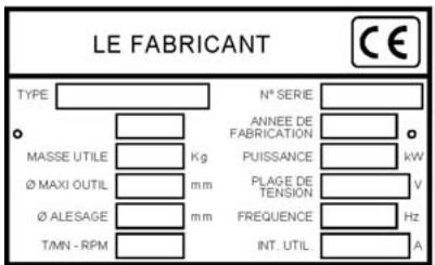
Instruction plate
FAILURE TO COMPLY WITH THESE WARNINGS COULD RESULT IN DEATH OR SERIOUS BODILY INJURY.

DO
DO carefully read and understand all the instructions before operating the saw.
DO always keep all guards in place.
DO aways wear safety approved hearing, eye, head and respiratory protection.
DO keep all parts of your body away from the blade and all other moving parts.
DO know how to stop the saw quickly in case of an emergency.
DO shut off the engine and allow it to cool before refueling.
DO inspect the blade, flanges and shafts for damage before installing the blade.
DO use only blades marked with a maximum operating speed greater than the blade shaft speed.
DO use caution and follow the instructions when loading and unloading the saw.
DO NOT
DO NOT allow other persons to be near the saw when starting, refueling or when cutting.
DO NOT operate gasoline engines in an enclosed area unless it is properly vented.
DO NOT use damaged equipment or blades.
DO NOT operate the saw in areas of combustible material. Sparks from the saw could cause a fire or an explosion.
DO NOT allow blade exposure from the guard to be over 180 degrees.
DO NOT leave the saw unattended with the motor running.
DO NOT operate the saw while under the influence of drugs or alcohol.
1 - USE
• Use : wet sawing new and old concrete and asphal
- Tools : Diamond Blades - water cooled ∅ 350 mm or 400 mm or 450 mm - bore 25.4 mm
(Information from your usual supplier).
3 – DESCRIPTION OF THE MACHINE
01 -Handle
02 -Lowering wheel
03 -Graduated scale
04 -Water intake tap
05 -Service spanner
06 -Engine Moteur
12 -Motor tensioning screw
13 -Tank
14 -Motor stop
15 -Circuit breaker
16 - Connector
17 -RCCB
18 -RCCB connector
19 - Wheel Lock
4 - HANDLING - TRANSPORT
Switch off the disk prior to moving the machine on jobsite.

Remove the disk prior to hoisting, loading, unloading and transporting the machine on jobsite.
• Height of the handle-bar adjustable by pivoting.
- To position the floorsaw on the site, simply push it. It will move easily on its four wheels without starting the engine.
- For transporting by vehicle or by any kind of lifting gear, there is a factory-fitted hoisting point on the machine.
5 – CHECK BEFORE STARTING

Please read the instructions for use prior to operating the machine for the first time.

Moteur off.
The working area must be completely cleared, well lit and all safety hazards removed (no water or dangerous
objects in the vicinity).


The operator must wear protective clothing appropriate to the work he is doing.

The use of ear protection is mandatory.

Any persons not involved in the work should leave the working area.

Use only blades marked with a maximum operating speed greater than blade shaft speed
Petrol engine machine (consult the engine maintenance manual):


Take into account the working conditions from health and safety point of view.
• Check that the fuel tank is full.
- Check that the engine oil level is correct. As the engine often operates at an angle, check the oil level (with the engine horizontal) frequently to ensure that it never falls below the second mark on the dipstick.
• For starting up refer to the engine handbook.
Machine with electric motor. Check the following:

- ELECTRICAL SAFETY : Operate this machine only on a supply equipped with a 30 mA earthed current-limiting circuitbreaker. Otherwise, consult our catalogue for appropriate models.
- The RCCB must be used correctly, including testing it regularly. For tools supplied with an integral RCCB in the cable or in the mains plug, if the cable or plug has been damaged, repairs must be carried out by the manufacturer, one of his agents or by a qualified repair workshop to avoid any risks resulting from errors.
- Motor power supply: reinforced electric cable with 4 (3P+E) or 5 (3P+N+E) conductors 2.5 mm2 for lengths less than 100 m.
• Earthing of the machine (mandatory).
• Mains voltage (400 V).
- Direction of rotation of the motor : Direction of rotation on the right hand side of the cover (if the motor does not turn in the direction required
6 – FITTING THE BLADE
Motor off.

Disconnect by removing the plug.
- Set the machine in the high position.
- Disconnet the water pipe from the blade guard.
• Unscrew the nut (K) from the guard [FIG. 1]. - Lift up guard (A).
• Fit the diamond blade.

Take care about the direction of rotation which is shown by an arrow on one of the faces (direction of rotation on the right side of the guard) Make sure the contact faces of flanges (B and C) of blade and the axle are clean.
- Firmly lock screw (D) using the spanner supplied with the machine whilst immobilising the blade by hand.
- Replace the protection guard (A).
- Close the guard water tap (G) [Fig 2].
• Reconnect the water pipe (G). - Tighten nut (K).

Replace all protective covers for your safety and that of other persons.
Note: how to adjust the « zero » according to the diameter of the blade :
• The blade must be closed to the floor.
- Loosen the screw (H) [FIG. 3]
- Line up the « zero » with the pointer, then tight the screw (H).
7 - STARTING UP

Danger : risk of injury.

Always pay extreme care and attention to the preparation of the machine before starting up.

Remove all adjustment tools and wrenches from floor and machine.

Always keep blade guard in place.
- Fill the tank with water, or connect with the water network.
- Mark the floor by drawing a line in the place to be cut.
- Fold down the front guide and position the machine so that the guide (F) and the blade line up with the mark.
Engine :
- Start the engine: refer to the instructions in the manufacturer's service manual.
Electric motor :
- Switch on by pressing knob I on the circuit breaker.
- Allow the engine to warm up.
- Open the water inlet tap (G).
- Increase the engine speed to maximum.
- Low the wheel lock (E) [FIG.3], in order to turn the wheel (2).
- Lower the blade to the desired depth indicated on the side scale on the ratchet placed on the side. We recommend a slow descent to avoid stalling the engine.
- Start moving down to the depth of cut required, indicated on the graduated scale fitted on the side. A slow descent is recommended to prevent stalling the motor.
- Once the required depth is reached, lock the wheel (2) by raising the block wheel (E).

Ensure that the water supply is abundant, when cutting wet.
8 - STOPPING THE MACHINE

Moteur off.
- Low the block wheel (E) [FIG.3] and turn the whell (2) to release the blade from the groove.
- Lock the machine in the high position by means of the block wheel (E).
• Turn off the water supply. - Allow the engine to turn at low speed.
- Stop the engine (consult the engine maintenance manual).

Emergency stop (engine) : Operate the switch on the machine's control panel.
9 – INCIDENTS DURING SAWING
Several causes can result in the blade stopping in the sawing groove or the machine stopping:
• Tension of the belt.
- Lack of fuel.
• Excessively fast feed or descent, etc.
- In all cases remove the blade from the groove and check the machine thoroughly.
Entrust repairs to authorised dealer only.
10 - MAINTENANCE

"Engine Maintenance": refer to the engine maintenance booklet.
• After use, clean the machine.
- Lubrication: apply a moderate amount of bearing lubricant to the nipples in the depth adjustment chassis (depending on the frequency of use).
- The spindle bearings must be greased after 8 hours of use, with a grease gun by pumping three to five times the grease into the greaser of the bearings. Only use a Super lithium 12 based grease in compliance with the NLG1 GRADE 2 consistency.
- Every 40 hours grease : depth control adjustment screw.
OIL
- Check ENGINE OIL daily. Read engine owners manual for O I L and OIL FILTER change intervals. Use :
- SAE 10W30 motor oil with API class MS, SD, SE or better for PETROL engines.
o API class CD or CE for Hatz diesel.

Dispose of the old oil as laid down by the regulations in force.
To empty the motor, place a funnel at the drain outlet (V) [FIG. 3].
AIR FILTER :
- Read engine owners manual for maintenance intervals. For extremely dusty conditions you may have to clean the air filter element 2 to 3 times a day.
- Replace any damaged filters or gaskets.

Store in a safe place out of reach of children.
Remove all adjustment tools and wrenches.
Store diamond tool in a safe place so it cannot be bent or damaged.
11 – MOTOR BELT TENSION
After several hours of use it may be necessary to adjust the tension of the belts (moderately). To do this proceed as follows:
- Release the screws fixing the motor to the chassis.
- Turn the tensioning screw (N) at the front of the machine one quarter turn; this screw pushes the motor backwards [FIG. 1].
- At normal tension, counterlock the nut of the screw (N).
- Relock the motor fixing screws.

Never set belts beyond original tension.
12 – IMPORTANT RECOMMENDATIONS
- Periodically tighten all nuts and bolts, particularly after the first few hours of operation.
- Check the tension of the belt. Tighten it, as instructed.
- When storing the machine, we recommend removing the blade and storing it carefully.
- Check that the blade is properly sprayed by inspecting the holes in the fork regularly.
• Tighten the blade firmly. - Make sure the contact faces of flanges, blade and axle are clean.

The manufacturer declines all responsibility for loss or damage resulting from misuse or any modification, alteration or powering that does not conform to the manufacturer's original specifications.

At the work station, the sound pressure level may exceed 85 db (A). In this case, individual protection measures must be taken.

When working in a limited or closed area, make sure that the ventilation is adequate. The exhaust gases contain carbon monoxide (exposure to this toxic gas can cause loss of consciousness and can be fatal).
13 - REPAIRS
SAV
We carry out all repairs in the shortest possible time and at the most economical prices (see overleaf for our address).
14 – SPARE PARTS
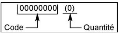
For quick supply of spare parts and to avoid any lost time it is essential to quote the data on the manufacturer's plate fixed to the machine and the part number of the part to be replaced with every order.
In the event of deterioration and scrapping of the machine, the following items must be disposed of in accordance with the requirements of the legislation in force.
Main materials :
- Motor : Aluminium (AL) - Steel (AC), Copper (CU), Polyamide (PA)
- Machine : Steel sheet (AC), Cast iron (FT) Aluminium (AL)
The instructions for use and spare parts found in this document are for information only and are not binding. As part of our product quality improvement policy, we reserve the right to make any and all technical modifications without prior notice.
11 - TENSIONE CINGHIA MOTORE
The warranty is acknowledged as of the date of purchase (date of the invoice of the distributor) and is valid for a period of 12 months.
2. WARRANTY
The warranty is limited to the free of charge replacement of parts recognised as defective by Husqvarna (excluding wear components and consumables) providing the repair is made within after-sales service of Husqvarna or a recognised Husqvarna repair centre.
The manufacturer is not responsible for any direct or indirect, material or immaterial, damages caused to persons or things by failure of the machine or the non operation of the machine.
3. WARRANTY CONDITIONS
To benefit the warranty, it is necessary to return the joined warranty certificate, duly completed, to Husqvarna within eight days of the purchase.
In case of failure of the machine during the warranty period, our after-sales services will inform you of the appropriate and most effective method of dealing with your claim and advise you if necessary of your nearest approved service centre.
As an alternative, you may return, at your cost, the machine together with a written description of the problem and damages with a copy of the invoice directly to our after sales department where upon a full investigation will be instigated without delay.
4, EXCLUSIONS
Warranty will not be applied for damages or failures caused by :
- incorrect use, error in transportation, handling or maintenance, - use of incorrect fuel or lubricants not advised by Husqvarna, - use of non-genuine parts or accessories
- repairs made by non approved service centres, - use of incorrect specifications of cutting tools. (We suggest the use of Husqvarna tools).
The goods are returned at the sole responsibility of the Buyer who must appeal against the transporter in the usual manner without delay.
Español
CONDICIONES DE GARANTIA
1. DURACION
CONDITIONS DE GARANTIE
1. DURÉE
Theorem 1.2. (A) Let f be a finite field and let g be the set of all elements of f . Then
Chardith, and the Morlhan, are a good choice of the
Warranty certificate
- Certificat de garantie
• Garantie-Zertifikat
Place here CE sticker with serial N°
To benefit from the warranty, it is mandatory to return, within eight days after the purchase, the attached warranty certificate.
Warranty certificate
Certificat de garantie • Garantie-Zertitikat • Certificato di garanzia • Garantie bewijs • Certificado de garantia • Certificado de garantia • Garanticertifikat
Company :
Société • Gesellschaft • Societa • Maatchappij • Sociedade • sociedad • Företag
Address :
Adresse • Adresse • indirizzo • Adres • Endereco • Direccion • Adress
Date of Acquisition :
Date d'achat • Datum des Kaufs • Data di acquisto • Datum van aankoop • Data de compra • Fecha de comprar • Inköpsdatum
Machine Type :
Type de la machine • Maschinen Type • Tipo della macchina • Machine Type • Tipo de maquina • Tipo de maquina • Maskintyp
Machine Serial Nr :
- FR - ASSURANCE DE CONFORMITÉ UE
- GB - EC DECLARATION OF CONFORMITY
- GB - ENVIRONMENTAL INFORMATION
- MANUTENTION TRANSPORT
- RECOMMANDATIONS IMPORTANTES
- THIS DOCUMENT WILL
- GENERAL SAFETY INSTRUCTIONS
- SPECIAL INSTRUCTIONS
- FAILURE TO COMPLY WITH THESE WARNINGS COULD RESULT IN DEATH OR SERIOUS BODILY INJURY
- USE
- DESCRIPTION OF THE MACHINE
- HANDLING - TRANSPORT
- CHECK BEFORE STARTING
- FITTING THE BLADE
- DISCONNECT BY REMOVING THE PLUG
- STARTING UP
- ALWAYS KEEP BLADE GUARD IN PLACE
- ENGINE
- ELECTRIC MOTOR
- STOPPING THE MACHINE
- INCIDENTS DURING SAWING
- MAINTENANCE
- MOTOR BELT TENSION
- IMPORTANT RECOMMENDATIONS
- REPAIRS
- SPARE PARTS
- MAIN MATERIALS
- TENSIONE CINGHIA MOTORE
- WARRANTY
- WARRANTY CONDITIONS
- 4, EXCLUSIONS
- ESPAÑOL
- CONDICIONES DE GARANTIA
- DURACION
- CONDITIONS DE GARANTIE
- DURÉE
- WARRANTY CERTIFICATE
- PLACE HERE CE STICKER WITH SERIAL N°
- TO BENEFIT FROM THE WARRANTY, IT IS MANDATORY TO RETURN, WITHIN EIGHT DAYS AFTER THE PURCHASE, THE ATTACHED WARRANTY CERTIFICATE
- COMPANY
- ADDRESS
- DATE OF ACQUISITION
- MACHINE TYPE
- MACHINE SERIAL NR
Brand : HUSQVARNA
Model : FS 400 LV
Category : Construction Equipment