
PG 680 - Construction Equipment HUSQVARNA - Free user manual and instructions
Find the device manual for free PG 680 HUSQVARNA in PDF.

| Product Type | Floor Grinding Machine |
| Brand | HUSQVARNA |
| Model | PG 680 |
| Grinding width | 680 mm (27 in) |
| Grinding discs | 3 x 240 mm (9.5 in) |
| Weight | 385 kg (850 lbs) |
| Total grinding pressure | 300 kg (660 lbs) |
| Motor power | 12.5 kW (17.0 hp) three-phase 380-480 V |
| Grinding disc speed | 600 - 1200 rpm |
| Planetary head speed | 5 - 70 rpm |
| Rotation direction | Independent FWD/REV control for discs and planetary head |
| Electrical supply | Three-phase, 380-480 V, grounding mandatory |
| Sound level (power) | 105 dB(A) measured, 106 dB(A) guaranteed |
| Sound level (pressure) | 88 dB(A) at user's ears |
| Vibration levels | Right handle: 2.7 m/s², left handle: 4.8 m/s² |
| Main functions | Polishing of marble, terrazzo, granite and concrete; Dual Drive Technology™; dry or wet grinding |
| Main components | Hour meter, electrical cabinet, planetary and grinding motors, control panel, dust guard |
| Safety | Emergency stop, overcurrent protection, ground fault, undervoltage; mandatory PPE (helmet, hearing protection, goggles, dust mask, gloves, boots) |
| Maintenance and cleaning | Daily check of head locks, head inspection, weekly planetary seal cleaning, electrical cabinet cleaning every 2 months, internal inspection every 6 months |
| Spare parts and repairability | Belt, bearings, grinding heads, springs, planetary seal, diamonds; mechanical overhauls after 12-36 months |
| General information | Manufactured by Husqvarna AB, Sweden; compliant with CE directives 2006/42/EC, 2004/108/EC, 2006/95/EC |
Frequently Asked Questions - PG 680 HUSQVARNA
User questions about PG 680 HUSQVARNA
0 question about this device. Answer the ones you know or ask your own.
Ask a new question about this device
Download the instructions for your Construction Equipment in PDF format for free! Find your manual PG 680 - HUSQVARNA and take your electronic device back in hand. On this page are published all the documents necessary for the use of your device. PG 680 by HUSQVARNA.
USER MANUAL PG 680 HUSQVARNA
natural_image
Icon of an open book inside a circular frame (no text or symbols)
Operator's manual
Please read the operator's manual carefully and make sure you understand the instructions before using the machine.

natural_image
Line drawing of a cleaning machine inside a circle (no text or symbols)GB ES DE FR
Contents
English
Contents
Key to symbols 4
Safety Instructions 6
Introduction 7
Transport 7
Storage 7
What is what 8
Setting up/Operation 10
Changing the diamonds 12
Variable speed drives/ frequency converters 13
Faults and trouble shooting 16
Diamonds 18
Diamond selection 19
Maintenance 23
Maintenance schedule 27
Technical data 28
Key to symbols
Key to symbols
The symbols below are used on the machine and in this Operator's Manual. It is important that the user understands the significance of these in order to work with the machine safely.

Please read the operator's manual carefully and make sure you understand the instructions before using the machine.

WARNING! Dust forms when grinding which can cause injuries if inhaled. Use an approved breathing mask. Always provide for good ventilation.

Always wear:
• Approved protective helmet
• Approved hearing protection
- Protective goggles or a visor.
- Dust forms when grinding, which can cause injuries if inhaled. Use dust mask.

Always wear sturdy non-slip boots with steel toe-caps.

Always wear approved protective gloves.
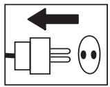
Inspection and/or maintenance should be carried out with the motor switched off and the plug disconnected.

Visual check.
Regular cleaning is required.

This product is in accordance with applicable EC directives.
Safety Instructions

WARNING
Under no circumstances may the machine be started without observing the safety instructions. Should the user fail to comply with these, Husqvarna Construction Products Sweden AB or its representatives are free from all liability both directly and indirectly. Read through these operating instructions and make sure that you understand the contents before starting to use the machine. Should you, after reading these safety instructions, still feel uncertain about the safety risks involved you must not use the machine, please contact your dealer for more information.
- Please read the operator's manual carefully.
- Only qualified staff should be allowed to operate machinery.
- Never use a machine that is faulty. Carry out the checks, maintenance and service instructions described in this manual. All repairs not covered in this manual must be performed by a repairer nominated by either the manufacturer or distributor.
- Always wear personal safety equipment such as sturdy non-slip boots, ear protection, dust mask and approved eye protection.
- The machine should not be used in areas where potential for fire or explosions exist.
- Machinery should only be started when grinding heads are resting on the ground unless carrying out a testing procedure as outlined in this manual.
- The machine should not be started without the rubber dust skirt attached. It is essential a good seal between machine and floor be established for safety, especially when operating in dry grinding applications.
- When changing the grinding discs ensure power supply to the unit is OFF by engaging the Emergency Stop button and the power-plug disconnected.
- The machine should not be lifted by handles, motor, chassis or other parts. Transportation of the machine is best done on a pallet / skid to which the machine must be firmly secured.
-
Extreme caution must be used when moving machinery by hand on an inclined plane. Even the slightest slope can cause forces/momentum making the machinery impossible to brake manually.
-
Never use the machine if you are tired, if you have drunk alcohol, or if you are taking medication that could affect your vision, your judgement or your coordination.
- Never use a machine that has been modified in any way from its original specification.
- Be on your guard for electrical shocks. Avoid having body contact with lightning-conductors/metal in the ground.
- Never drag the machine by means of the cord and never pull out the plug by pulling the cord. Keep all cords and extension cords away from water, oil and sharp edges.
- Make sure the cord is not pinched in doors, fences or the like.
- Check that the cord and extension cord are intact and in good condition. Never use the machine if the cord is damaged, hand it in to an authorized service workshop for repair.
- Do not use a rolled up extension cord
- The machine should be connected to an earthed outlet socket.
- Check that the mains voltage corresponds with that stated on the rating plate on the machine.
- Ensure the cord is behind you when you start to use the machine so that the cord will not be damaged.
At no time should lifting of machinery be attempted without mechanical means such as a hoist or fork lift.

WARNING!
Overexposure to vibration can lead to circulatory damage or nerve damage in people who have impaired circulation. Contact your doctor if you experience symptoms of overexposure to vibration. These symptoms include numbness, loss of feeling, tingling, pricking, pain, loss of strength, changes in skin colour or condition. These symptoms normally appear in the fingers, hands or wrists.
Introduction
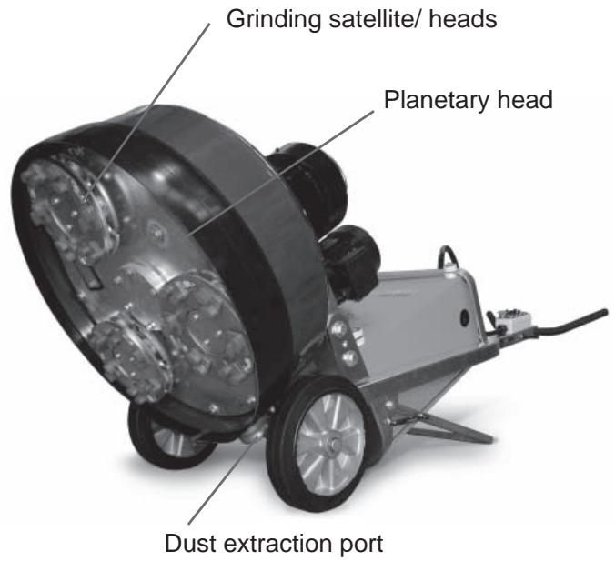
The Husqvarna PG 680/820 floor surfacing machines are designed for wet or dry grinding of marble, terrazzo, granite and concrete. Their applications range from rough grinding through to a polished finish.
This manual covers the Husqvarna PG 680/820 series of floor grinders equipped with twin motor drive here after referred to as Dual Drive Technology™.
It is extremely important all users be familiar with the contents of this manual before
commencing operation of either machine. Failure to do so may result in damage to machinery or expose operator to unnecessary dangers.

IMPORTANT!
Only staff that have received the necessary education, both practically and theoretically concerning their usage should operate the machinery.
Transportation
The machine comes equipped with inbuilt advanced electronic systems called variable speed drives or frequency converters. These drives enable the variable speed and direction component of each of the motors. The drives are located in the steel cabinet mounted on the machine chassis.
As with all electronic equipment, the drives are sensitive to excessive vibration, rough treatment and high levels of dust. Much care and attention has been given by the manufacturer to ensure maximal protection is given to the drives. Note the shock absorbing mounting system used to mount the steel cabinet on the machine chassis/frame.
When transporting, it is important to ensure the machinery is properly secured at all times to eliminate “bouncing” of the variable speed drives. Ensure the chassis or frame section of the machine is secured down at all times when in transit.
The machine should always be transported under cover limiting the exposed to natural elements – in particular rain and snow.

IMPORTANT!
The machine should not be lifted by handle, motor, chassis or other parts. Transportation of the machine is best done on a pallet/skid to which the machine must be firmly secured. Do not attempt to slide the tines/forks from a fork lift under grinding heads unless on a pallet/skid. Failure to do so can cause irreparable damage to grinding heads of machine and internal parts.
It is recommended that machinery be transported with a set of diamonds attached at all times to ensure protection of locking mechanism for diamond plates.
Storage
The machine should always be stored in a dry place when not in use.
What is what
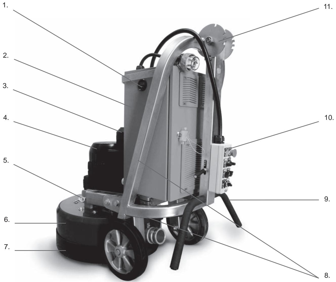
What is what
- Hour counter
- Electrical cabinet
- Planetary head motor 1.5kW/1Hp
- Grinding/Satellite heads motor 11kW/15Hp
- Lifting lugs
- Cover/Shroud
-
Skirt
-
Chassis/Frame
- Handle bars
- Control Panel
- Handle bar adjuster
The machine can be divided into two main parts. These can be identified as follows:
-
Chassis/Frame section – comprising handle bars,
electrical cabinet, steel frame and wheels. -
Head – comprising of motors, cover, grinding/satellite/
planetary heads and internal components.
The machine has been manufactured to allow movement between the chassis and head via the connection point at the lifting lugs and chassis pins. This movement is important during the grinding process as it creates a “floating” effect for the head.
The floating gives the head a self-leveling effect, negating the need to adjust the height of the head as the machine passes over floor areas with different slopes or undulations.
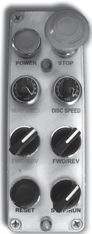
Control panel
The control panel consists of a number of switches and dials giving 8 separate controls (see picture).
Power - This button, when depressed, will turn on power supply to the unit when the EMERGENCY STOP button has been released.
Emergency Stop - When pushed will immediately shut down machine by totally stopping power supply to drives/ frequency converters in electrical cabinet.
Head Speed - Direction control for planetary head rotation.
Fwd/Rev (Yellow) - Direction control for planetary head rotation.
Disc Speed - Speed control for grinding heads.
Fwd/Rev (Red) - Direction control for grinding heads.
Reset - Will clear fault function/error message on drive/frequency converter (located in electrical cabinet) in case of fault occurring.
Stop/Run - To start or stop machine during normal operation.

IMPORTANT!
It is important to use the STOP/RUN switch to control the running of the machine, not the EMERGENCY STOP button. Each time the EMERGENCY STOP button is pressed it shuts down the drive/frequency converter. Frequently powering up and down of the drive/frequency converter will reduce the life span of the drive/ frequency converter.

IMPORTANT!
Planetary head and grinding heads are set to both turn in the same direction (i.e. both in clockwise rotation or both in counter-clockwise rotation).
Clockwise rotation of speed control will increase speed of planetary head and grinding heads.
Control panel
Setting up/Operation


Position grinder on the working area. Make sure there are diamonds underneath machine and that the head locks/shear pins are tight.

IMPORTANT!
When using the machine, each grinding head must always have the same diamond type and number of diamonds as the other grinding heads. Each grinding head must have diamonds the same height as the other grinding heads.
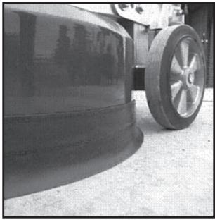
Adjust rubber skirt so that a good seal is established between the floor and head of machine (see picture below). Ensure join in skirt is at the front of the machine. Setting of the skirt is essential to obtain good dust extraction and eliminate the possibility of airborne dust when dry grinding.
natural_image
Close-up of a car wheel rim and rear wheel on pavement (no visible text or symbols)Set handle to most comfortable working height using adjustment lever.

IMPORTANT!
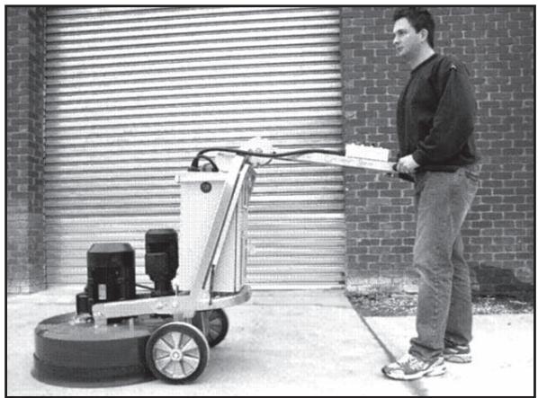
It is recommended that this height be set as close as possible to the height of the operator's hip bone. When the machine is running, there will be a grinding force/pull to one side that can be felt through the handlebars. Use the hip to resist this force instead of trying to control this through the arms (such positioning will be much easier for the operator using the machine over prolonged periods of tim.
natural_image
Man standing beside a cleaning machine in front of a brick wall (no visible text or symbols)Powering up machine
i. Ensure the STOP/RUN switch is set on Stop (rotate counter clockwise).
ii. Plug power supply to machine. Only turn power on at switch once fully connected.
iii. Disengage Emergency Stop button (twist clockwise).
iv. Depress Power button. On doing so, a soft “clunk” should be heard to come from within the electrical cabinet. This indicates the line contactors have engaged, supplying power to the drives/frequency converters.
Setting Speed and direction
On the control panel there is a FORWARD/REVERSE and Speed dial knob. Generally, when starting the machine for the first time on any given application, it is advised the speed setting should not exceed 7, initially.
When the operator is comfortable with the application, speed may be increased.
Speed and direction setting is often a matter of personal choice. Operators are encouraged to experiment to find which settings best suit the given applications. The following table lists some suggested set-ups for different applications.
| Application | Planetary head direction | Planetary head speed | Grinding disc direction | Grinding disc speed |
| Ceramic tile adhesive removal | FWD | 6-7 | FWD | 8-10 |
| Carpet glue removal | FWD | 5-7 | FWD | 8-10 |
| Epoxy paint removal | FWD | 5-10 | FWD | 8-10 |
| Rain damaged concrete | FWD | 7-10 | FWD | 8-10 |
| Smoothen exposed aggregate | FWD | 7-8 | FWD | 8-10 |
| Lippage removal in terrazzo/stone tiles | FWD | 5-7 | FWD | 8-10 |
| Concrete polishing with resin bond pads | FWD | 10 | FWD | 8-10 |
| PIRANHATM scraper tool | REV | 3-5 | REV | 3-5 |
| FLEXORTM flexible heads | FWD | 5-7 | FWD | 5-7 |
| Bushhammer/Scarrifier tools | FWD | 5 | FWD | 5-7 |
| Re-grouting procedure during HiPERFLOORTM process | FWD | 8-10 | FWD | 3-5 |

IMPORTANT!
In the above table, FWD & FWD are listed together to indicate direction settings in the same direction (i.e. It can also be REV/REV). The only application where direction settings must be in the same directions and also direction specific is when using the PIRA-NHA™ scraper tools. In this particular application the setting must be in the REV/REV direction.
Direction of rotation
The correlation between FWD/REV & Clockwise/Counter clockwise rotation can be said as follows if looking at the grinding discs from underneath the machine:
- REV—Clockwise.
- FWD—Reverse.
As mentioned, when the machine is in operation it will “pull” to one side. The direction of pull is determined by the planetary head direction of rotation. The head of the machine will pull to the right (and therefore, will be felt on the right hip of the operator) when the planetary head is set in the REVERSE direction.
This sideways pull can be very useful when grinding, particularly along a wall. Set the machine so that it pulls towards the wall, and then control the machine so it can just touch the wall. This will ensure a grind close to the wall or object.
Direction is also a matter of personal preference. It should be noted, however, that when both grinding discs and planetary heads are running in the same direction, a more powerful grinding force is created between the diamond abrasives and floor being ground. The end result is higher productivity than when the discs are set to run in opposite directions. It is here that you will also experience the benefit of Dual Drive Technology™.
Production tip - To improve the cutting efficiency of diamonds, change directions on a regular basis. This will work both sides of the diamond crystals, keeping the abrasives as sharp as possible by creating maximal exposure of the diamond crystal.
Once both a speed and direction have been nominated, switch on dust extraction or vacuum device.

IMPORTANT!
It is highly recommended to use the Husq-varna DC 5500 dust extraction system for complete dust control.
Standing behind machine with handlebars set as described earlier, apply a small amount of downward pressure on the handle. Switch the machine to run mode using the STOP/RUN switch on the control panel. The machine should start smoothly and accelerate to the selected speed over a period of 5 seconds
Changing the diamonds
As different applications require different selections of diamond tools, there will be many occasions when the grinding discs need to be changed.
Following is a guide for this procedure.
Preparation
- Ensure STOP/RUN switch is in STOP position as unintentional starting of machine while changing discs can result in serious injury.
- Have a set of gloves ready, as diamonds can get very hot during dry grinding applications.
Changing
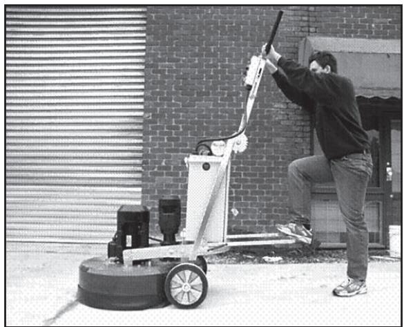
- Set handle in upright position (illustrated right).
- Pull back on handle to lift grinding head off the ground.
- Lay machine back on the ground.
- Put on gloves.
- Remove grinding disc by slightly rotating disc and then pull off (direction that the discs will need to be rotated will depend on the direction the machine was last running).
- Check to ensure all head locks/shear pins are tight.
- Once new diamonds have been attached, reverse procedure to lower machine to ground.
- As new diamonds may be a different height to set being previously used, re-adjust skirt to ensure good seal is established with the floor.
natural_image
Person using a cleaning or dust removal machine on a rooftop, no visible text or symbols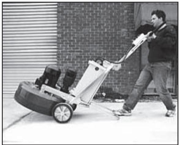
natural_image
Man pushing a large lawn mower on a paved area, with brick wall and window in background (no visible text or symbols)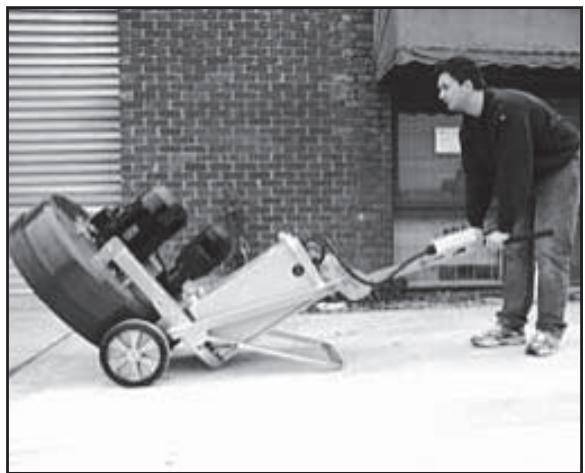
natural_image
Man pushing a manual lawn mower outdoors, no visible text or symbolsVariable speed drives/ frequency converters
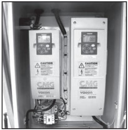
Each Husqvarna PG 680 & 820 is equipped with 2 variable speed drive or frequency converter. This unit is incorporated into the machine for the following reasons:
1. Functional
- Manipulate incoming power to enable increase/decrease in speed & direction change.
- Regulate current and voltage supply to the motors to ensure motors run at optimum levels (e.g. torque boost).
2. Protection/Diagnostic
Protection
- Monitors incoming power to ensure suitability for machine and application being performed.
- Controls current being drawn by motors to ensure motors are running within safe operational limits (to prevent damage to motor).
- Monitors load on machine to ensure the grinder is not being overloaded thus offering protection for belt, bearings and other internal components.
- Protects motors from faulty power supply (e.g. running on 2 phases).
Diagnostic
- Identifies electrical faults with the machine and registers fault code.
- Has monitoring menus that help isolate cause of potential electrical faults.
- Monitoring menus also enable operator to gauge how hard machine is working. Whilst it is not essential for an operator to intimately know every feature of the variable speed drives or frequency converters, it is useful to be familiar with both the fault codes as well as some of the monitoring menus.
Keypad/Display
Each variable speed drive or frequency converter has a keypad which will appear as illustrated on the right when the machine has power connected to it.
natural_image
Interior view of an electrical enclosure showing two CMG voltage meters with warning labels and wiring (no readable text beyond labels)
- Run direction (fwd or rev)
- Indicates if unit is either stopped or running
- Up key
- Left key
- Down key
- Reset button
- Output mode (Hertz in this example)
- Output value
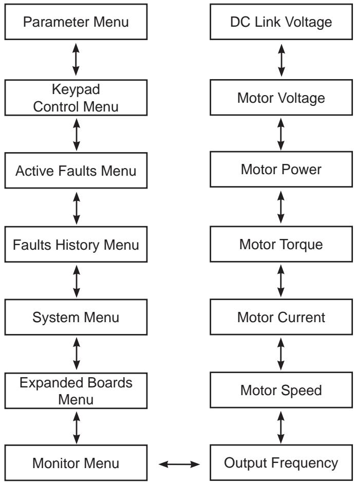
| Monitor screen | Information provided |
| OUTPUT FREQUENCY | Frequency motor is running at when machine is running. |
| REF. FREQUENCY | Frequency speed control dial is set to. |
| MOTOR SPEED | Speed of motor when machine is running. |
| MOTOR CURRENT | Current draw of motor when machine is running. |
| MOTOR TORQUE | Percentage of motor torque when machine is running. |
| MOTOR POWER | Percentage of motor power when machine is running. |
| MOTOR VOLTAGE | Percentage of motor voltage when machine is running. |
| DC LINK VOLTAGE | Indicates quality of power supply. |
The menu tree illustrated on this page outlines the important menu options that provide useful information for monitoring and diagnostic purposes when using the machine.
As can be seen on the menu tree to the right, when the machine is turned on, the variable speed drives or frequency converters are set to display the Output Frequency to the motor (a zero value will register when the machine is in stand-by mode).
The Output Frequency page also falls under the Monitor Menu.
It can be seen from the left hand column, the two primary menus important to the operator are the Monitor Menu and Fault History menu.
Navigation through the menu tree is achieved by using the up, down, left and right keys on the keypad (see previous page).
flowchart
graph TD
    A["Parameter Menu"] <--> B["Keypad Control Menu"]
    B <--> C["Active Faults Menu"]
    C <--> D["Faults History Menu"]
    D <--> E["System Menu"]
    E <--> F["Expanded Boards Menu"]
    F <--> G["Monitor Menu"]

    H["DC Link Voltage"] <--> I["Motor Voltage"]
    I <--> J["Motor Power"]
    J <--> K["Motor Torque"]
    K <--> L["Motor Current"]
    L <--> M["Motor Speed"]
    M <--> N["Output Frequency"]
Menus and information they provide
The following menu items/screens on the variable speed drive/frequency converters provide the following useful information to the operator.
OUTPUT FREQUENCY (Monitor Menu)
This screen tells the operator the frequency the motor is running at when the machine is in operation. The value for output frequency should be constant when the machine is running. If there is a fluctuation in output frequency when the machine is running, generally this indicates the motor is running at or near the limit of its programmed current limit. The current limits (predetermined and set by Husqvarna Constructions Products) are as follows:
- Large motor (which information is found on the large variable speed drive/frequency converter) - 25 amps.
- Small motor (which information is found on the small variable speed drive/frequency converter) - 5 amps.
If there is a fluctuation in output frequency when the machine is in operation, it is advisable to check the motor current as well. This can be found by pressing the UP arrow on the keypad 3 times. For trouble free operation concerning current issues, it is best to keep output current at or around 21 amps (for the large motor). The current draw of the motor can be reduced by reducing the speed of the motor using the speed dial on the control panel near the handle bars.
Generally speaking, most over-current problems will be associated with the large motor (and therefore, monitored on the large variable speed drive/frequency converter). Keep the current draw on the small motor under 3.5amps for consistent operation.
MOTOR CURRENT (Monitor Menu)
This screen displays the current draw of the corresponding motor (i.e. large variable speed drive/frequency converter monitors function of large motor, small variable speed drive/frequency converter monitors function of small motor) when the motor is running.
See comments already covered under OUTPUT FREQUENCY relating to motor current.
DC LINK VOLTAGE (Monitor Menu)
This screen displays the quality of the power supply to the machine. It will read higher values when the machine in standby and lower values when the machine is in operation.
FAULT HISTORY
The fault history menu stores the last series of faults experienced by the variable speed drive/frequency converter. If there is a recurring fault pattern experienced by the machine, the information can be obtained from the fault history menu. For more on faults, see trouble shooting faults
Faults and trouble shooting
Faults and trouble shooting
When either one of the variable speed drives or frequency converters in the machine experience a fault and “trip” out, they will cease to run and an error message will appear flashing on the keypad display (see picture below).
The following list are the most commonly experienced faults and possible action steps.
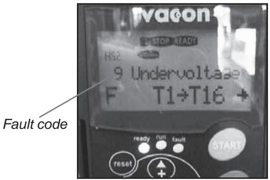
| Fault Code | Possible Cause | Action |
| 1—OVERCURRENT | Motor being worked too hard and drawing extra current. | Check current being drawn when machine is running. Reduce speed setting and current draw back into acceptable limits as described on previous page. |
| Short circuit on output side of variable speed drives or frequency converters. | Check wiring in plugs connected to motor cables or inside connection boxes on motors. | |
| Motor failure (very rare) | Have motor tested and replace if required. | |
| 3—EARTH FAULT | Short circuit on output side of variable speed drives or frequency converters. | Check wiring in plugs connected to motor cables or inside connection boxes on motors. |
| Motor failure (very rare) | Have motor tested and replace if required. | |
| 9—UNDERVOLTAGE | Insufficient voltage supply to machine. | Check power supply and ensure correct voltage. |
| Power supply to variable speed drives or frequency converters has been turned off. | Re-connect power to grinder. | |
| 11—OUTPUT PHASE SUPERVISION | Short circuit on output side of variable speed drives or frequency converters. | Check wiring in plugs connected to motor cables or inside connection boxes on motors. |
| Motor failure (very rare) | Have motor tested and replace if required. | |
| 14—UNIT OVER TEMPERATURE | Variable speed drives or frequency converter over temperature due to high temperature working environment or faulty temperature sensor. | Open door on electrical cabinet to increase ventilation.Have variable speed drives or frequency converter tested by service agent. |
| 15—MOTOR STALLED | Motor being worked too hard and drawing extra current. | Check current being drawn when machine is running. Reduce speed setting and current draw back into acceptable limits as described on previous page. |
| Mechanical jam preventing motor from turning. | Try rotating grinding discs and planetary head by hand to see if jam exists | |
| 16 - MOTOR OVERTEMPERATURE | Motor being worked too hard and drawing extra current. | Check current being drawn when machine is running. Reduce speed setting and current draw back into acceptable limits as described on previous page. |
Faults and trouble shooting
Further problems that may be experienced when using the grinder and potential solutions are as follows:
| Problem | Possible Cause | Potential Solution |
| GRINDER IS HARD TO HOLD ONTO | Not enough diamonds under the machine (if grinding thick glue or soft floors, too few diamonds under the machine will greatly increase the load on grinder and operator). Usually also accompanied by high current draw by large motor. | Increase number of diamonds under machine to reduce load on grinder and operator. |
| Large motor not working (this can be caused by fault with motor, fault with wiring to motor, or fault with large variable speed drive or frequency converter). | Check large motor is plugged in. Check there are no faults on larger variable speed drive or frequency converter. Check that large variable speed drive or frequency converter is on. Check that large variable speed drive or frequency converter is functioning properly (unplug both motors, set display on keypad to Output Frequency, switch machine to RUN, see if numbers on screen change from zero and begin counting up. If numbers stay on zero, large variable speed drive or frequency converter is not receiving run command from switch on control panel. Machine needs to be checked by an electrician or by Husqvarna Construction Products | |
| Drive belt is slipping. | Remove belt tensioner cover plate on bottom of machine and check there is no water or dust on the inside of the machine that may be causing the belt to slip on the drive pulleys. | |
| Drive belt is broken (this can be confirmed by turning one of the grinding heads by hand. If all grinding heads rotate together, belt is not broken. If only one grinding head turns, belt is broken). | Replace internal drive belt. | |
| GRINDER SOUNDS LIKE IT IS OVERREVVING | Small planetary drive motor not plugged in. | Check small planetary drive motor is plugged in. |
| Small motor not working (this can be caused by fault with motor, fault with wiring to the motor, or fault with large variable speed drive or frequency converter). | Check small motor is plugged in. Check there are no faults on small variable speed drive or frequency converter. Check that small variable speed drive and frequency converter is on. Check that small variable speed drive or frequency converter is functioning properly (unplug both motors, set display on keypad to Output Frequency, switch machine to RUN, see if numbers on screen change from zero and begin counting up. If numbers stay on zero, small variable speed drive or frequency converter is not receiving run command from witch on control panel. Machine needs to be checked by an electrician or Husqvarna Construction Products. | |
| GRINDER IS JUMPING AROUND | Grinding heads may be worn-out or damaged. | Check grinding heads for broken parts or excess movement. |
| Diamonds may not be fitted correctly or different height diamonds may be on the grinding heads. | Check to ensure all diamonds are fitted correctly and are the same height. | |
| Head locks may be loose or missing. | Check to ensure all head locks are present and tight. |
Diamonds
Background
Diamond abrasives usually consist of 2 components:
- Diamond powder (also known as diamond crystals or grit). By changing the size of the diamond powder or grit, we can change how coarse or fine the scratches will be that are left behind from the grinding process.
- A binding agent (metal or resin). Diamond powder is mixed and suspended in either a metal or resin binding agent. When suspended in a metal binding agent, the finished product is referred to as a Metal Bond or Sintered diamond segment. When suspended
in a resin binding agent, the finished product is referred to as a Resin Bond diamond segment or pad. By changing the hardness of the binding agent, we can change how fast or slow the diamond abrasive will wear.
General Principles
The following are general rules regarding diamond segments in grinding applications. As with all general rules there are exceptions or cases when it is not the case.
DIAMOND GRIT SIZE
Changing the size of the diamond grit to a smaller particle/grit size will effect the performance of the diamond tool in the following ways:
• Create a finer scratch pattern.
- Increase the life of the diamond tool.
The opposite will occur when changing to a larger particle/grit size.
BINDING AGENT—METAL BOND OR RESIN BOND Increasing hardness of bond will:
- Increase life of diamond tool.
• Decrease production rate. - Cause diamond tool to leave finer scratches in dry - grinding applications (when compared to a softer bond diamond tool with the same diamond grit size).
The opposite will occur when making the metal or resin bond softer.
NUMBER OF DIAMOND SEGMENTS/PADS UNDER THE MACHINE
Increasing the number of segments under the machine will:
- Reduce pressure on each individual diamond segment.- Reduce wear rate on diamond segments.
- Reduce load on the machine and cause the grinder to draw less current.
- Create a smoother scratch pattern (particularly on soft floors).
The opposite will occur when decreasing the number of segments under the machine.
WET AND DRY GRINDING
When using diamond segments wet, the following principles apply:
• Production rates will be higher than dry grinding.
- Diamond segments will wear faster (due to presence of slurry) and therefore, harder bonds can be used (when comparing with dry grinding).
• Scratches from diamond grit will be deeper.
When using diamond segments dry, the following principles apply:
- Production rates will be slower on harder materials than if wet grinding.
- Softer bond segments will be required in order to encourage segment wear (as there will be not slurry to help diamond segments to wear).
- Scratches from diamond grit will not be as deep compared to if it were also used for wet grinding.
- There will be more heat generated by the diamond segment.
Summary of diamond principles
Diamond segments need to wear in order to achieve productivity. Diamond segment wear can be influenced by the following factors:
- Pressure.
- Hardness of bond.
- Diamond grit size.
- Presence of water.
• Number of segments under the machine. - Adding an additional abrasive (e.g. sand, silicone carbide) on the floor will increase wear.
natural_image
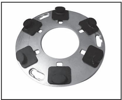
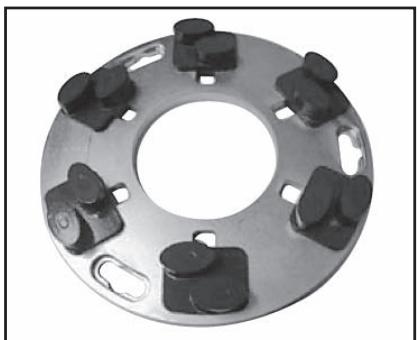
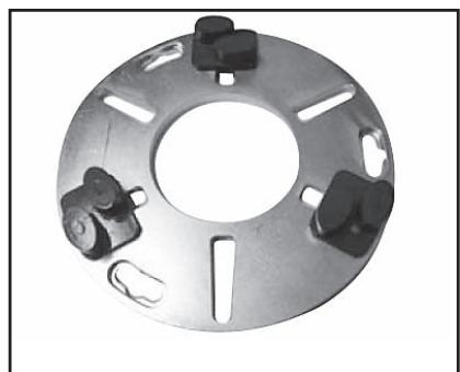
Circular mechanical component with six black buttons and a central hole, no visible text or symbols.Full set of single segments
natural_image
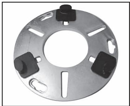
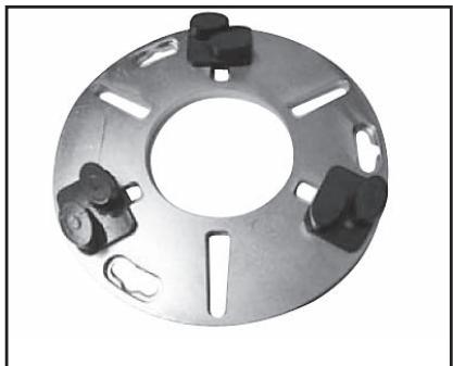
Metal flange with four black buttons and a central hole, no text or symbols visibleHalf set of single segments
natural_image
Circular mechanical component with multiple black plastic clips and a central hole (no text or symbols visible)Full set of twin segments
natural_image
Metal mechanical flange component with multiple mounting holes and a central hole (no text or symbols visible)Half set of twin segments
Generally speaking, the faster a diamond segment wears, the faster the productivity will be. By varying the above factors, changes can also be made to effect the following:
- Scratch pattern.
• Current draw of machine. - Flatness of floor (see next section).
- Ease of operation.
Diamond selection
The following section covers important factors to consider when selecting the diamond segment you are going to use for a given application.
Grinding disc set-up
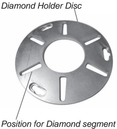
The way diamond segments are set-up on the grinding heads of the machine will also greatly influence the performance of the machine, the productivity levels and also the finished floor quality.
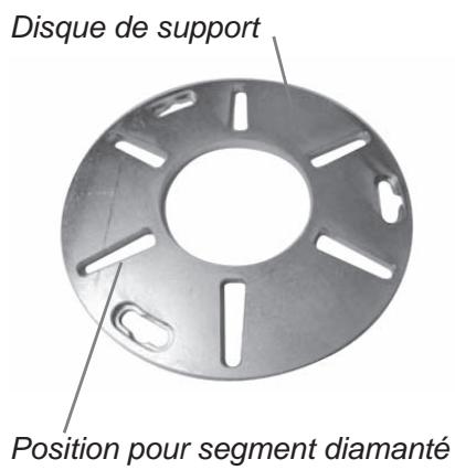
There are basically two types of diamond configurations that can be used when using the grinder:
-
Full set of diamonds – when there are diamonds placed
at each of the six positions on the diamond holder discs
(see pictures above). -
Half set of diamonds – when there are diamonds placed
at three alternating positions on the diamond holder discs (see pictures above).
Full and half sets of diamonds
By changing the way the diamonds are set-up on the diamond holder discs, an operator can significantly effect the performance of the machine and therefore, the finished product.
HALF-SET OF DIAMONDS
When the diamonds are set-up as a half-set, they tend to follow the surface of the floor. Similar to a tripod for a camera, which can be placed on an uneven surface and yet still find a stable footing.
The half-set diamond configuration should only be used when a flat floor finish is not required.
FULL-SET OF DIAMONDS
When the diamonds are set-up as a full-set, they tend not to follow the surface of the floor. If the floor has undulations, the machine will grind the high areas yet miss the low spots (unless the high areas are ground down first).
The full-set diamond configuration should be used when a flat floor finish is desired.
The below table gives some examples of possible applications for the two arrangements:
| Application | Full set is best | Half set is best |
| Ceramic tile adhesive removal | X | |
| Carpet glue removal | X | |
| Epoxy paint removal | X | |
| Vinyl adhesive removal | X | |
| Rain damaged concrete | X | |
| Smoothen exposed aggregate | X | |
| Lippage removal in terrazzo/stone tiles | X | |
| Surface polishing of concrete floors | X | |
| Grinding to expose aggregate in concrete polishing application | X | |
| Remove lippage from terrazzo/natural stone tiles | X | |
| Flatten undulations in concrete floors | X | |
| Re-polish floors that have been ground before | X |
Selecting the correct diamonds for your application
The following suggestions cover the basic principles for diamond selection for different applications.
| Application | Metal bond | Grit size | Full-set | Half set | Singles / Twins |
| Flatten floor - Hard concrete | SOFT | 16 or 30 | X | S | |
| Flatten floor - Medium concrete | MEDIUM | 16 or 30 | X | S | |
| Flatten floor - Soft concrete | HARD | 16 or 30 | X | T | |
| Ceramic tile adhesive removal | HARD | 6, 16 or 30 | X | S/T | |
| Vinyl or Carpet glue removal - Hard concrete | SOFT | 16 or 30 | X | S/T | |
| Vinyl or Carpet glue removal - Medium concrete | MEDIUM | 6 or 16 | X | T | |
| Vinyl or Carpet glue removal - Soft concrete | HARD | 6 or 16 | X | T | |
| Epoxy paint removal - Hard concrete | SOFT | 6, 16 or 30 | X | X | S |
| Epoxy paint removal - Medium concrete | MEDIUM | 6, 16 or 30 | X | S | |
| Epoxy paint removal - Soft concrete | HARD | 6, 16 or 30 | X | S/T | |
| Rain damaged concrete | HARD | 16 or 30 | X | S/T | |
| Smoothen exposed aggregate | HARD | 16 or 30 | X | S/T | |
| Lippage removal in terrazzo - stone tiles | SOFT | 30 or 60 | X | S | |
| Surface polishing of concrete floors - Hard concrete | SOFT | 60 | X | S/T | |
| Surface polishing of concrete floors - Medium concrete | MEDIUM | 60 | X | S/T | |
| Surface polishing of concrete floors - Soft concrete | HARD | 60 | X | T | |
| Grinding to exposed aggregate in concrete - Hard concrete | SOFT | 16 or 30 | X | S | |
| Grinding to exposed aggregate in concrete - Medium concrete | MEDIUM | 16 or 30 | X | S | |
| Grinding to exposed aggregate in concrete - Soft concrete | HARD | 16 or 30 | X | T | |
| Flatten undulation in concrete floors - Hard concrete | SOFT | 16 or 30 | X | S | |
| Flatten undulation in concrete floors - Medium concrete | MEDIUM | 16 or 30 | X | S | |
| Flatten undulation in concrete floors - Soft concrete | HARD | 16 or 30 | X | T |
Determining the hardness of concrete
All concrete may feel hard (particularly if you fall over on it), so what do we mean when we talk about hard, medium and soft concrete?
All concretes are measured by their compressive strength and depending on which part of the world you are from, different compressive strength indices (e.g. PSi & MPa). Generally speaking, the higher the compressive strength rating, the harder the concrete and therefore, the harder it will be to grind.
However, other factors beside compressive strength ratings determine how hard the floor will be, and therefore, the correct diamond selection. Since grinding normally only deals with the surface of the concrete (top 5mm or 1/4 inch), often the way the concrete floor has been finished or the condition of the surface will have a greater bearing on what type of diamond to select, rather than the compressive strength rating of the concrete.
SURFACE FACTORS TO CONSIDER WHEN MAKING A DIAMOND SELECTION
Generally speaking, if a concrete surface is very smooth (i.e. Most likely it has been heavily trowelled/helicoptered), the concrete will behave as if it has a high compressive strength and therefore, require a soft bond segment.
Accordingly, if a concrete surface is coarse/aggressive (e.g. rain-damaged, shot blasted, scarified, exposed aggregate e.t.c.), the concrete will behave as if it has a low compressive strength and therefore, require a hard bond segment.
Surface coatings/contaminants (e.g. Epoxy coatings, ceramic tile adhesives, levelling compounds/screeds) will often have a larger bearing on what diamond to select, than will the compressive strength of the concrete.
As a general rule, when grinding a concrete slab for the first time and you are unsure about its hardness, always begin with harder bond diamonds under the machine. This will ensure the least amount of wear on the diamond segments. If a hard diamond segment is not suited to the application, all it has cost is a little amount of time without wearing out the diamonds.
If performed the other way around (i.e. a soft segment is used to begin with) and the concrete is soft or possesses an abrasive surface or surface contaminant, it is quite possible to wear-out a considerable amount of diamond in very short period of time.
Maintenance
Used correctly, the machine is an extremely low-maintenance and reliable.

This section covers the general maintenance items that need attention on a periodic basis.
There are three main mechanical items to check:
- Grinding Heads.
- Planetary drive system.
- Planetary seal.
Grinding heads
There are 2 different grinding head options:
- Conventional / Demolition heads—designed for heavy duty preparation grinding where an extremely robust system is required.
- Spring steel head system—designed more for finishing or lighter grinding applications.
CONVENTIONAL/DEMOLITION HEADS
The below diagram illustrates the main parts comprising this type of grinding head.
- Head mate
- Head plate
- Head lock
- Head spring
The interrelation between the above four components enables a dynamic system which is both robust and flexible.
The head pins are fixed to the head plate giving rigidity and stability. The head mate is situated above the head plate and is held in place by a series of holes – head pin holes.
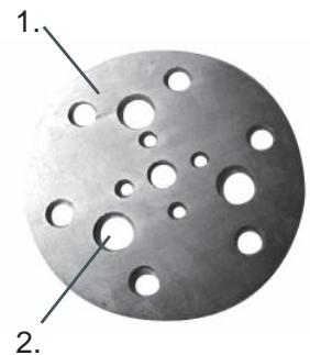
natural_image
Circular metallic object with multiple holes, labeled 1 and 2 (no text or symbols on the object itself)- Head mate
- Head pin hole
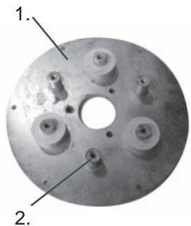
natural_image
Close-up of a metallic circular mechanical component with multiple bolt holes and a central hole (no text or symbols visible)- Head plate
- Head pins
Between the head plate and head mate are 3 white silicone springs which give shock absorption and flexibility in the system.
The head pins are able to move within the head pin holes, creating a shock absorber type system similar to that in most motor vehicles.
Over an extended period of time, the head pin holes wear open. Along with this, the head pins wear and reduce in diameter. This combined wearing of the two creates excessive movement or “slop” within the grinding heads. This “slop” will eventually cause vibration whilst the machine is operating.
Routine checks for slop in the grinding heads are recommended. Life expectancy for grinding heads can vary between 6 and 12 months depending on amount of usage.
Replacement heads are available and simply bolt into place when the old ones are removed
Maintenance
Spring Steel Heads
The below diagrams illustrate the main parts comprising this type of grinding head.
Diagram 1
- Spring steel spring
- Head plate
- Cushion ring
- Head mate
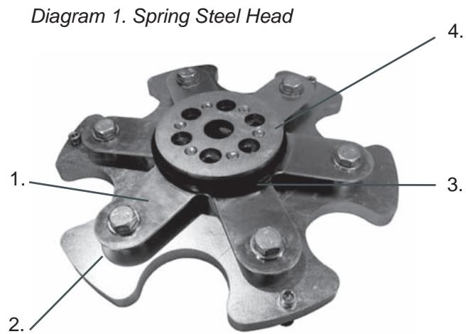
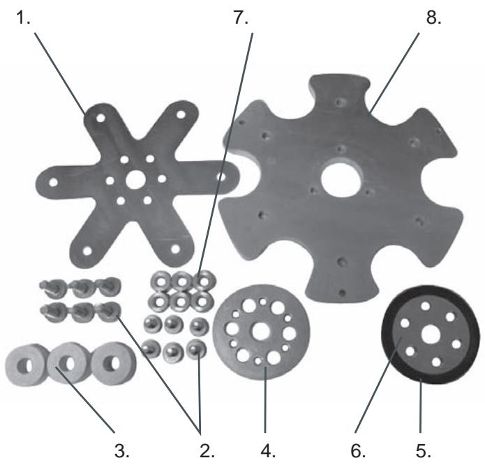
Diagram 2
- Spring steel springs
- Bolts
- Silicone spring
- Head mate
- Cushion ring
- Head buddy
- Spacers
- Head plate
Between the head plate and head mate are a series of white silicone springs, spacers and the spring steel spring which give shock absorption and flexibility in the system.
Unlike with the conventional/demolition heads, the spring steel heads are able to move in a flexible manner without any moving parts due to the presence of the spring steel spring.
Over an extended period of time the spring steel spring fatigues and the spring steel “fingers” begin to break off. This creates irregular movement within the grinding heads and will cause vibration when the machine is in operation.
Routine checks for broken “fingers” in the spring steel grinding heads are recommended. Life expectancy for grinding heads can vary between 6 and 12 months depending on the amount of usage.
Replacement spring steel springs are available and can be replaced without throwing the grinding head away.
The spring steel heads can also be made less flexible by the addition of a second spring steel spring.
Diagram 2
Grinding Heads Drive System
The grinder comes equipped with Dual Drive Technology™. As the grinding discs are driven by the large motor via an internal belt, and because the belt is sealed inside the machine, there is no maintenance regarding this drive system until a major service (belt and bearing replacement) is due. This is typically following 12-36 months of operation.
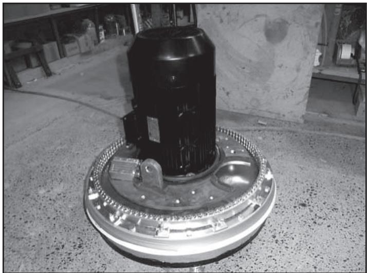
Planetary Drive System
The second component to the Dual Drive Technology™ system is the planetary head drive system which is powered by the secondary or small motor and gearbox arrangement. This system is on the outside of the machine and will require routine maintenance. The planetary drive system can be seen as illustrated diagram 1.
Diagram 1
- Grinding heads motor
- Motor terminal box
- Machine cover
- Gearbox mounting bracket
- Gearbox flange bracket
- Gearbox
- Motor terminal box
- Planetary drive motor
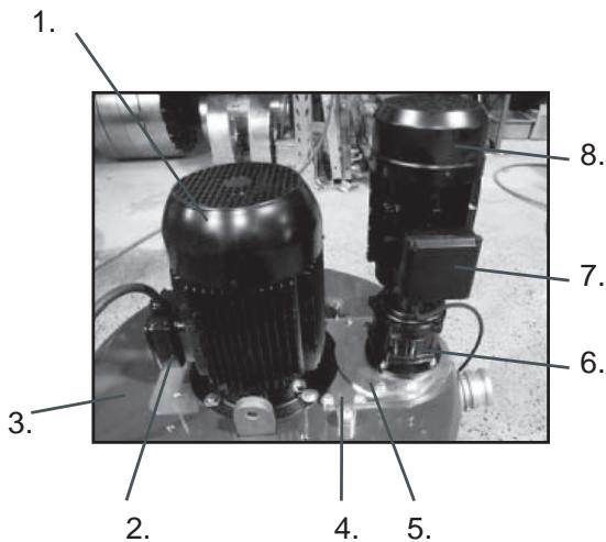
Diagram 1. Planetary Drive System
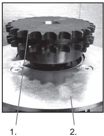
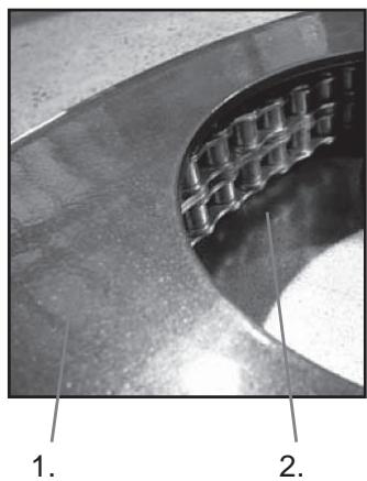
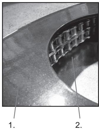
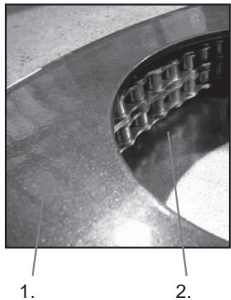
Beneath the gearbox and concealed by the mounting brackets and machine cover, there is a planetary drive sprocket situated on the output shaft of the gearbox. This planetary sprocket engages with the chain ring (also located beneath the machine cover) and together form the main drive mechanism for the planetary drive system. This system is a dry system (i.e. it is not required for there to be lubrication between the planetary drive sprocket and chain ring), to allow any dust that may come into contact with the chain ring to fall back out again.

IMOPRTANT!
Lubrication of this system will cause dust to build up in chain ring and drastically shorten the life of both the chain ring and planetary drive sprocket.
Diagram 2
natural_image
Close-up of a mechanical gear assembly with labeled parts (1 and 2), no readable text or symbols beyond labelsDiagram 3
natural_image
Close-up of a curved mechanical component with grid-like cutouts, labeled 1 and 2 (no text or symbols on the main subject)- Planetary drive sprocket
- Gearbox flange bracket
Diagram 3
- Machine cover
- Chain ring
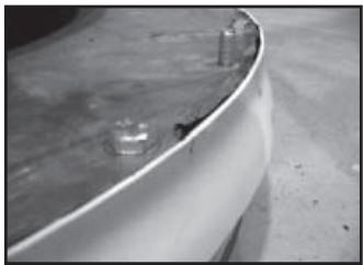
Diagram 4
- Planetary seal
As the chain ring and planetary drive sprocket are located beneath the cover of the machine, yet on the outside of the machine, there lies the potential that they can be exposed to dust and other debris created during the grinding process.
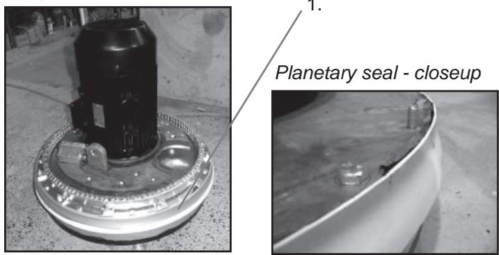
To prevent this as much as possible, a planetary seal has been installed to stop dust and other particles from coming into contact with the planetary drive mechanism.
Diagram 4
Maintenance
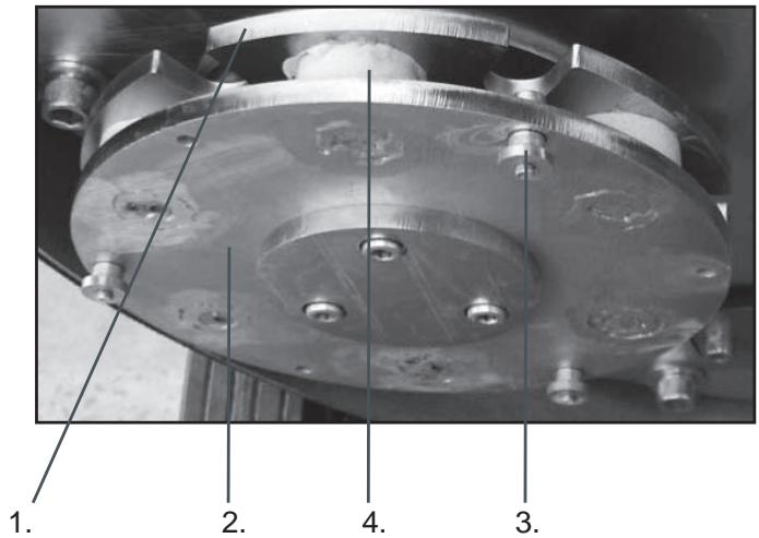
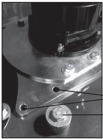
The effectiveness of the planetary seal can be monitored by the simple removal of the planetary motor / gearbox system by removing the four bolts shown below.
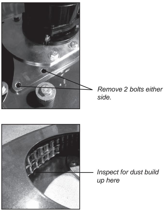
Remove 2 bolts either side.
Inspect for dust build
up here
If the planetary seal is working effectively, there should be a very minimal amount of dust observed under the cover of the machine. If there is a build-up of 5-6mm (1/4 inch), then it is more than likely it is time to remove the machine cover and check the condition of the planetary seal.
natural_image
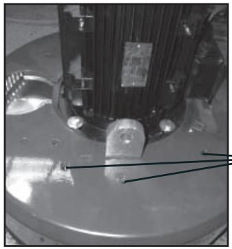
Close-up of a mechanical component with mounting holes and a central shaft (no visible text or symbols)Remove this bolt.
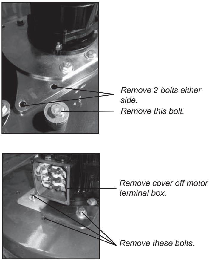
Remove 2 bolts either side.
Remove this bolt.
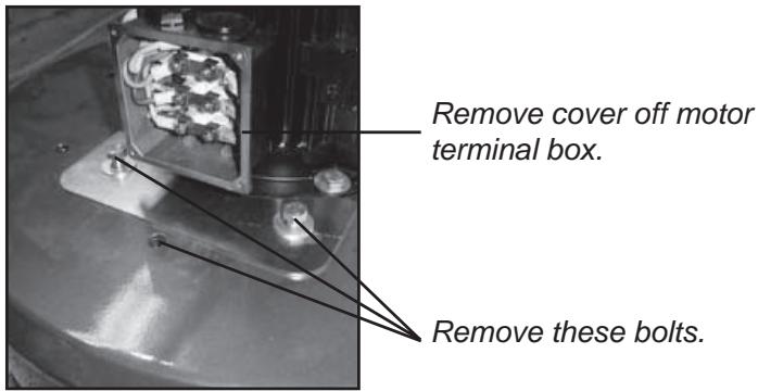
Remove cover off motor terminal box.
Remove these bolts.

natural_image
Close-up of a mechanical component mounted on a circular base, with no visible text or symbols.Lift off machine cover to reveal chain ring and planetary seal.
If planetary seal is worn or needs replacement, contact your Husqvarna Construction Products distributor for a new planetary seal replacement kit.
Maintenance schedule

| Item | Action | Frequency |
| Check that head locks are tight. | Tighten head locks and re-set in thread-locking compound if required (Suggested thread-locking compound Loctite 680) | Daily |
| Inspect heads for slop/broken “fingers” if using spring steel heads. | Examine machine heads while machine tipped back.Disconnect Planetary Drive motor (small motor) and run discs at lowest speed. Check to see how concentric/true grinding heads are running. | Daily |
| Check effectiveness of planetary seal. | Remove planetary head motor/gearbox system and check for presence of dust under machine cover . | Weekly |
| Check condition of chain ring. | Remove planetary head motor/gearbox system and inspect chain links in chain ring. Ensure links are clean and free from build-up. | Weekly with Planetary Seal |
| Check condition of Drive Sprocket. | Remove planetary head motor/gearbox system and inspect condition of planetary drive sprocket. | Weekly with Planetary Seal |
| Inspect internal components of machine. | Remove belt tensioner cover plate and check inside machine for dust, moisture or belt fragments. Ensure to re-seal cover plate with silicone sealant. | 6 monthly |
| Clean contents of electrical cabinet. | Blow out inside of electrical cabinet and variable speed drives or frequency converters with DRY compressed air. | Every 2 months |

IMOPRTANT!
Prior to removing belt tensioner cover plate, ensure cover plate and area surrounding cover plate are totally clean. Avoid debris from entering into inside of machine.
Technical Data
| Technical Data | PG 820 | PG 680 |
| Grinding width | 820mm (32") | 680mm (27") |
| Grinding disc | 3x270mm (10.5") | 3x240mm (9.5") |
| Weight | 440kg (970lbs) | 385kg (850lbs) |
| Grinding pressure total | 335kg (737lbs) | 300kg (660lbs) |
| Grinding pressure per disc | 112kg (246lbs) | 100kg (220lbs) |
| Motor Power | 3-Phase 380-480V12.5kW(17.0hp) | 3-Phase 380-480V12.5kW(17.0hp) |
| Power per grinding disc | 4.15kW (5.7hp) | 4.15kW(5.7hp) |
| Grinding disc speed | 250 - 1100rpm | 600 - 1200rpm |
| Planetary head speed | 5 - 65rpm | 5 - 70rpm |
| Direction of rotation | Independent FWD/REV direction control on both grinding discs and planetary head. | |
| Power supply | 3 phase | 3 phase |
| Noise emissions (see note 1) | ||
| Sound power level, measured dB(A) | 105 | |
| Sound power level, guaranteed LWA dB(A) | 106 | |
| Sound levels (see note 2) | ||
| Sound pressure level at the operators ear, dB(A) | 88 | |
| Vibration levels, ahv (see note 3) | ||
| Handle right, m/s2 | 2,7 | |
| Handle left, m/s2 | 4,8 | |
Note 1: Noise emissions in the environment measured as sound power ( L_WA ) in conformity with EN 61029-1.
Note 2: Noise pressure level according to EN 61029-1. Reported data for noise pressure level has a typical statistical dispersion (standard deviation) of 1.0 dB(A).
Note 3: Vibration level according to EN 61029-1. Reported data for vibration level has a typical statistical dispersion (standard deviation) of 1 m/s^2 .
EC-declaration of conformity
(Applies to Europe only)
Husqvarna AB, SE-433 81 Göteborg, Sweden, tel: +46-31-949000, declares under sole responsibility that the Husqvarna PG 680, PG 820, from 2010's serial numbers and onwards (the year is clearly stated in plain text on the rating plate with subsequent serial number), conforms with the requirements of the COUNCIL'S DIRECTIVE:
• of May 17, 2006 “relating to machinery” 2006/42/EC
• of December 15, 2004 "relating to electromagnetic compatibility" 2004/108/EC.
• of December 12, 2006 "relating to electrical equipment" 2006/95/EC.
The following standards have been applied: EN ISO 12100:2003, EN 55014-1:2006, EN 55014-2/A1:2001, EN 61000-3-2:2006, EN 61000-3-3/A1/A2:2005, EN 13862/A1:2009.
Göteborg December 29, 2009
Henric Andersson

Vice President, Head of Power Cutters and Construction Equipment
Husqvarna AB
(Authorized representative for Husqvarna AB and responsible for technical documentation.)
Español
Índice
Panel de control
natural_image
Close-up of a car wheel rim and rear wheel on pavement (no visible text or symbols)natural_image
Man standing beside a cleaning machine in front of a brick wall (no visible text or symbols)natural_image
Man operating a large industrial machine outdoors, no visible text or symbols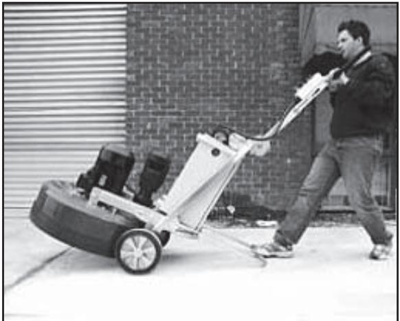
natural_image
Man pushing a large lawn mower on a paved area, with brick wall and window in background (no visible text or symbols)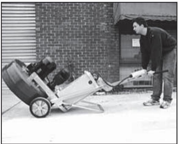
natural_image
Man pushing a manual lawn mower outdoors, no visible text or symbolsnatural_image
Interior view of an electrical enclosure showing two CMG voltage meters with warning labels and wiring (no readable text beyond labels)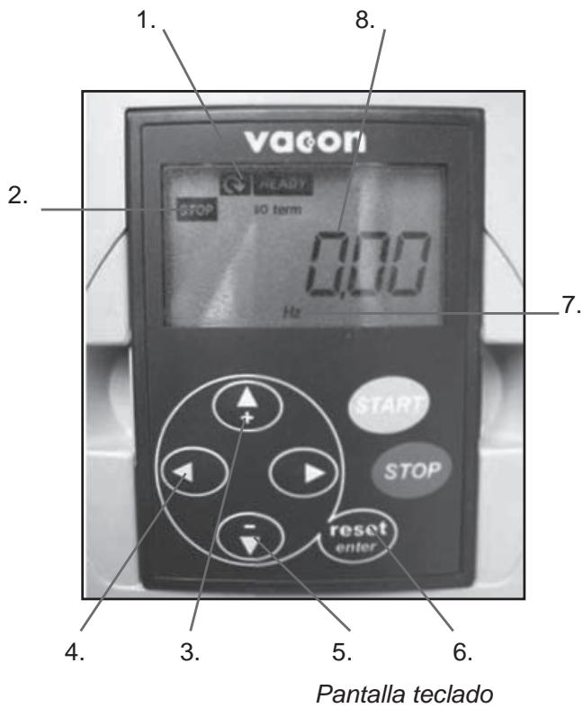
Teclado/pantalla
natural_image
Circular mechanical component with multiple black buttons and mounting holes, no visible text or symbolsnatural_image
Circular mechanical component with multiple black plastic clips and a central hole (no text or symbols visible)natural_image
Metal flange with four black buttons and a central hole, no text or symbols visiblenatural_image
Metal mechanical flange component with multiple mounting holes and a central hole (no text or symbols visible)natural_image
Close-up of a metallic circular mechanical component with multiple cylindrical features and a central hole, labeled with numbers 1 and 2 (no text or symbols on the part itself)natural_image
Close-up of a mechanical gear assembly with labeled parts (1 and 2), no readable text or symbols beyond labels.Diagrama 3
natural_image
Close-up of a curved mechanical component with internal grid pattern, labeled 1 and 2 (no text or symbols on the object itself)natural_image
Close-up of a mechanical component mounted on a circular base, no visible text or symbols1.
Junta planetaria – detalle
natural_image
Close-up of a curved metallic surface with small circular indentations, possibly a container or tank (no text or symbols visible)natural_image
Close-up of mechanical components with no visible text or symbolsnatural_image
Close-up of a metallic mechanical component with a grid-patterned inner surface (no visible text or symbols)natural_image
Close-up of a mechanical component with a central shaft and mounting holes (no visible text or symbols)Retire este perno.
natural_image
Close-up of a mechanical assembly with metallic components and mounting holes (no visible text or symbols)natural_image
Close-up of a mechanical component with internal cavity and mounting base (no visible text or symbols)natural_image
Close-up of a mechanical component mounted on a circular base, with no visible text or symbols.Maschinenteile
Steuerkasten
natural_image
Close-up of a car wheel rim and rear wheel on pavement (no visible text or symbols)natural_image
Man standing beside a cleaning machine in front of a brick wall (no visible text or symbols)natural_image
Man operating a large industrial machine outdoors, no visible text or symbols
natural_image
Man pushing a large lawn mower on a paved area, with brick wall and window in background (no visible text or symbols)
natural_image
Man pushing a manual lawn mower outdoors, no visible text or symbolsnatural_image
Two CMG voltage meters mounted in a cabinet, each with warning labels and digital displays (no readable text beyond labels)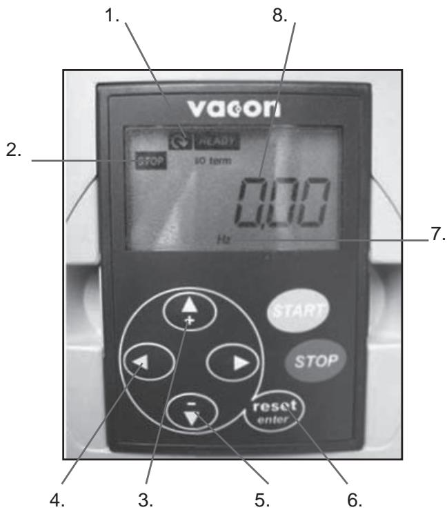
natural_image
Circular mechanical component with multiple black buttons and mounting holes, no visible text or symbolsnatural_image
Metal flange with four black buttons and a central hole, no text or symbols visiblenatural_image
Circular mechanical component with multiple black plastic components and mounting holes (no text or symbols visible)natural_image
Metal mechanical flange component with multiple bolted joints and a central hole (no text or symbols visible)natural_image
Close-up of a metallic circular mechanical component with multiple bolt holes and a central hole (no text or symbols visible)natural_image
Mechanical gear assembly with labeled parts (1 and 2), no text or symbols presentAbbildung 3

natural_image
Close-up of a curved mechanical component with grid-like internal structure, labeled 1 and 2 (no text or symbols on the object itself)natural_image
Close-up of a mechanical component mounted on a circular base, no visible text or symbols1.
natural_image
Close-up of a curved metallic surface with small circular indentations, possibly a container or tank (no text or symbols visible)Wartung
natural_image
Close-up of a mechanical assembly with metallic components and a central hub (no visible text or symbols)natural_image
Close-up of a metallic mechanical component with a grid-patterned inner surface (no visible text or symbols)natural_image
Close-up of a mechanical component with visible pins and a central shaft (no text or symbols)natural_image
Close-up of a mechanical assembly with metallic components and mounting holes (no visible text or symbols)natural_image
Close-up of a mechanical component with internal components and mounting base (no visible text or symbols)natural_image
Close-up of a mechanical component mounted on a circular base, with no visible text or symbols.Vice President, Head of Power Cutters and Construction Equipment
Husqvarna AB
Panneau de commande
natural_image
Close-up of a car wheel rim and rear wheel on pavement (no visible text or symbols)natural_image
Man standing beside a cleaning machine in front of a brick wall (no visible text or symbols)natural_image
Man operating a large industrial machine outdoors, no visible text or symbols
natural_image
Man pushing a large lawn mower on a paved area, with brick wall and window in background (no visible text or symbols)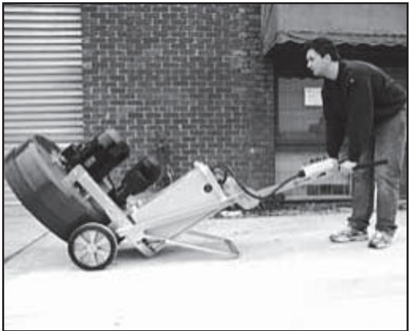
natural_image
Man pushing a manual lawn mower outdoors, no visible text or symbols2. Protection/Diagnostic
Protection
natural_image
Two CMG voltage meters mounted in a cabinet, each with warning labels and digital displays (no readable text beyond labels)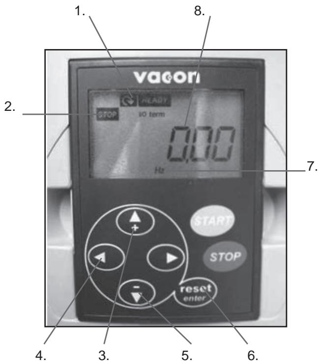
natural_image
Circular mechanical component with multiple black buttons and mounting holes, no visible text or symbolsJeu complet de segments simples
natural_image
Metal flange with four black buttons and a central hole, no text or symbols visiblenatural_image
Circular mechanical component with multiple black plastic components and mounting holes (no text or symbols visible)Jeu complet de segments dou- bles
natural_image
Metal mechanical flange component with multiple bolted features and central hole (no text or symbols visible)TÊTES CONVENTIONNELLES/DE DÉMOLITION
natural_image
Circular metallic plate with multiple holes, labeled 1 and 2 (no text or symbols on the plate itself)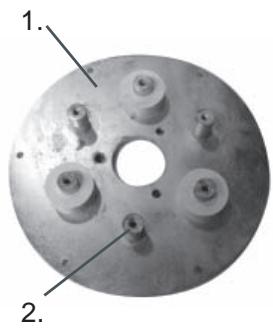
natural_image
Close-up of a metallic circular mechanical component with multiple bolt holes and a central hole (no text or symbols visible)natural_image
Close-up of a mechanical gear assembly with two labeled parts (1 and 2), no visible text or symbols on the gear itself.Diagramme 3
natural_image
Close-up of a curved mechanical component with internal grid structure, labeled 1 and 2 (no text or symbols on the object itself)natural_image
Close-up of a mechanical assembly with metallic components and a central hub (no visible text or symbols)natural_image
Close-up of a mechanical assembly with metallic components and mounting holes (no visible text or symbols)natural_image
Close-up of a mechanical component with a grid-patterned circular opening (no visible text or symbols)natural_image
Close-up of a mechanical component with internal components and mounting base (no visible text or symbols)natural_image
Close-up of a mechanical component with visible pins and mounting holes (no text or symbols)Retirez ce boulon.
natural_image
Close-up of a mechanical component mounted on a circular base, with no visible text or symbols.- Operator's manual
- Contents
- English
- Key to symbols
- Safety Instructions
- WARNING
- WARNING!
- Introduction
- IMPORTANT!
- Transportation
- Storage
- What is what
- Control panel
- Setting up/Operation
- Powering up machine
- Setting Speed and direction
- Direction of rotation
- Changing the diamonds
- Changing
- Variable speed drives/ frequency converters
- Functional
- Protection/Diagnostic
- Protection
- Diagnostic
- Keypad/Display
- Menus and information they provide
- OUTPUT FREQUENCY (Monitor Menu)
- MOTOR CURRENT (Monitor Menu)
- DC LINK VOLTAGE (Monitor Menu)
- FAULT HISTORY
- Faults and trouble shooting
- Diamonds
- Background
- General Principles
- DIAMOND GRIT SIZE
- NUMBER OF DIAMOND SEGMENTS/PADS UNDER THE MACHINE
- WET AND DRY GRINDING
- Summary of diamond principles
- Diamond selection
- Grinding disc set-up
- Full and half sets of diamonds
- HALF-SET OF DIAMONDS
- FULL-SET OF DIAMONDS
- Selecting the correct diamonds for your application
- Determining the hardness of concrete
- SURFACE FACTORS TO CONSIDER WHEN MAKING A DIAMOND SELECTION
- Maintenance
- Grinding heads
- CONVENTIONAL/DEMOLITION HEADS
- Spring Steel Heads
- Diagram 1
- Diagram 2
- Grinding Heads Drive System
- Planetary Drive System
- IMOPRTANT!
- Diagram 3
- Diagram 4
- Maintenance schedule
- EC-declaration of conformity
- Español
- Índice
- Teclado/pantalla
- Maschinenteile
- Wartung
- TÊTES CONVENTIONNELLES/DE DÉMOLITION
Brand : HUSQVARNA
Model : PG 680
Category : Construction Equipment