
EL-2607P/2607PG - Calculator SHARP - Free user manual and instructions
Find the device manual for free EL-2607P/2607PG SHARP in PDF.
| Product Type | Printing Calculator |
| Brand | SHARP |
| Model | EL-2607P / EL-2607PG |
| Working Capacity | 12 digits |
| Main Power Supply | AC 220-230 V, 50 Hz |
| Backup Power Supply | Lithium battery CR2032 (3 V) |
| Backup battery life | Approximately 2 years (at 25°C) |
| Printer Type | Mechanical printer |
| Print speed | Approximately 4.3 lines per second |
| Paper width | 57-58 mm |
| Maximum roll diameter | 80 mm |
| Power consumption | 67 mA |
| Weight | Approximately 1.9 kg (with battery) |
| Operating temperature range | 0 °C to 40 °C |
| Main functions | Basic calculations, percentage, tax (included/excluded), memory, average, grand total, printing, item count, markup/margin |
| Maintenance and cleaning | Soft dry cloth. Do not use solvents or a damp cloth. |
| Safety | Do not expose to water, moisture, or dust. Use only the specified voltage. Keep batteries out of reach of children. |
| Available spare parts | Ink ribbon, paper roll, CR2032 battery |
| Repairability | Entrust to a SHARP authorized dealer for repair |
| Included accessories | 1 lithium battery, 1 battery replacement label, 1 paper roll, 1 ink ribbon (installed), instruction manual |
Frequently Asked Questions - EL-2607P/2607PG SHARP
User questions about EL-2607P/2607PG SHARP
0 question about this device. Answer the ones you know or ask your own.
Ask a new question about this device
Download the instructions for your Calculator in PDF format for free! Find your manual EL-2607P/2607PG - SHARP and take your electronic device back in hand. On this page are published all the documents necessary for the use of your device. EL-2607P/2607PG by SHARP.
USER MANUAL EL-2607P/2607PG SHARP
OPERATION MANUAL
BEDIENUNGSANLEITUNG
MODE D'EMPLOI
MANUAL DE MANEJO
MANUAL DE INSTRUÇÕES
KÄYTTÖOHJE
Notes for handling Lithium batteries:
CAUTION
Danger of explosion if battery is incorrectly replaced.
Replace only with the same or equivalent type recommended by the manufacturer.
Dispose of used batteries according to the manufacturer's instructions.
The socket outlet shall be installed near the equipment and shall be easily accessible.
Vorsicht!
To insure trouble-free operation of your SHARP calculator, we recommend the following:
- The calculator should be kept in areas free from extreme temperature changes, moisture, and dust.
- A soft, dry cloth should be used to clean the calculator. Do not use solvents or a wet cloth.
- Since this product is not waterproof, do not use it or store it where fluids, for example water, can splash onto it. Raindrops, water spray, juice, coffee, steam, perspiration, etc. will also cause malfunction.
- While the memory protection battery is not installed, the tax / discount rate set up will be cleared upon terminating the AC power supply. The tax / discount rate set up will also be cleared when the memory protection battery is removed from the unit.
- If service should be required on this equipment, use only a SHARP servicing dealer, a SHARP approved service facility or SHARP repair service where available.
- Do not wind the AC cord around the body or otherwise forcibly bend or twist it.
CONTENTS
Page
- INSTALLING OF BATTERY FOR MEMORY PROTECTION .... 3
• OPERATING CONTROLS 4 - INK RIBBON REPLACEMENT .... 7
- PAPER ROLL REPLACEMENT .... 8
- ERRORS 9
- REPLACEMENT OF BATTERY FOR MEMORY PROTECTION....10
- SPECIFICATIONS .... 11
- RESETTING THE UNIT .... 13
• CALCULATION EXAMPLES ...... 129
• TAX RATE CALCULATIONS ...... 149
SHARP will not be liable nor responsible for any incidental or consequential economic or property damage caused by misuse and/or malfunctions of this product and its peripherals, unless such liability is acknowledged by law.
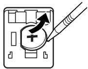
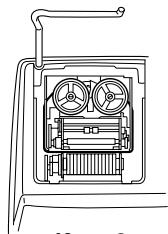
INSTALLING OF BATTERY FOR MEMORY PROTECTION
Before using for the first time, remove the attached lithium battery, and install it in the equipment according to the following procedure.
If the power cord is unplugged by accident when operating with AC power only, the tax / discount rate and the contents of memory set up will be lost.
1) Turn the power switch "OFF" and unplug the power supply plug from the outlet.
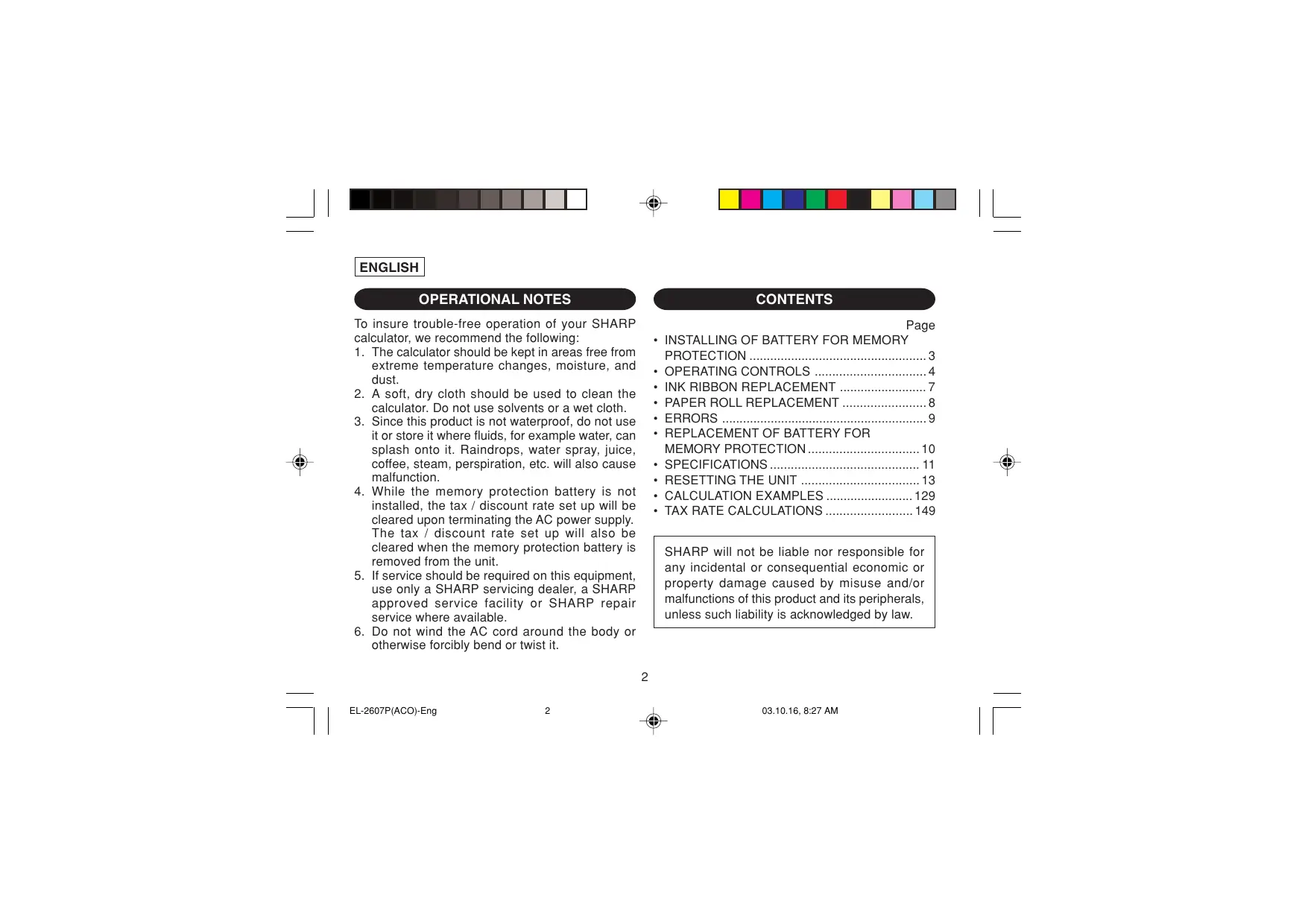
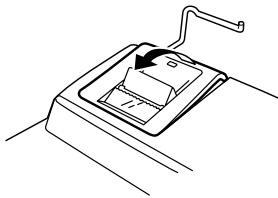
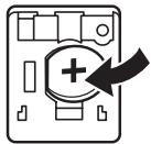
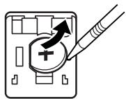
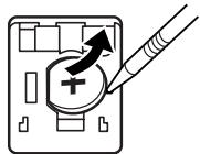
2) Remove the battery cover on the back of the unit. (Fig. 1)
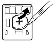
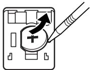
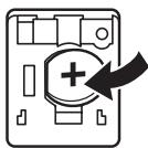
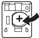
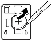
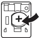
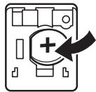
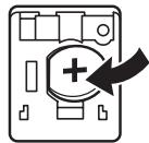
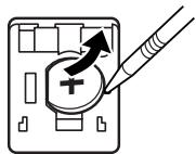
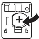
3) Wipe the battery well with a dry cloth and place the plus “+” side upward. (Fig. 2)
4) Replace the battery cover by reversing the removal procedure.
5) Press the RESET switch on the back of the unit (See page 13).
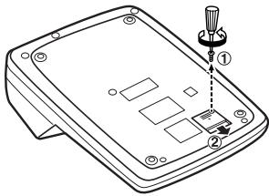
Fig. 1
natural_image
Diagram of a device with a plus sign and arrow indicating direction (no text or symbols)Fig. 2
After battery installation
- Connect the power supply plug to an outlet and turn the power switch "ON".
Check that "0." is displayed. If "0." is not displayed, remove the battery, reinstall it, and check the display again. - On the battery replacement date label found on the back of the unit, write down the month and year when the battery is installed, as a reference for the next battery replacement.
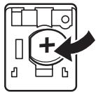
OPERATING CONTROLS
"OFF": Power off.
“●”: Power ON. Set to the non-print mode.
"P": Power ON. Set to the print mode.
“P•IC”: Power ON. Set to the print and item count mode.
1) The counter will count the number of times that the ± key has been pressed in addition.
Note: • Each time the -- key is used in subtraction, 1 will be subtracted from the count.
- The count is printed when the calculated result is obtained.
- Pressing of the *, ×, ÷, AVG or MU key clears the counter.
2) When the grand total/rate setting mode selector is in the ON position (GT), the counter will count the number of times that the calculation results have been stored in the grand total memory. To print and clear the count, press the GT key.
3) The memory item counter will count the number of times that the M^+ key has been pressed in the addition.
Note: • Each time the M- key is used in the subtraction, 1 will be subtracted from the count.
- The count is printed when the memory is recalled.
- Pressing of the *M key clears the counter.
Note: The counter has a maximum capacity of 3 digits (up to ±999 ). If the count exceeds the maximum, the counter will recount from zero.
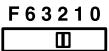
F63210
DECIMAL SELECTOR:
Presets the number of decimal places in the answer. In the “F” position, the answer is displayed in the floating decimal system.
K·A
CONSTANT/ADD MODE SELECTOR:
“K”: The following constant functions will be performed:
Multiplication:
The calculator will automatically remember the first number entered (the multiplicand) and ☒ instruction.
Division:
The calculator will automatically remember the second number entered (the divisor) and ÷ instruction.
“●”: Neutral
“A”: Use of the Add mode permits addition and subtraction of numbers without an entry of the decimal point. When the Add mode is activated, the decimal point is automatically positioned according to the decimal selector setting.
Use of ☐, ✗ and ÷ will automatically override the Add mode and decimally correct answers will be printed at the preset decimal position.

ROUNDING SELECTOR:
“↑”: An answer is rounded up.
"5/4": An answer is rounded off.
“↓”: An answer is rounded down.
Note: The decimal point floats during successive calculation by the use of × or ÷ .
If the decimal selector is set to "F" then the answer is always rounded down (↓).
RATE GT·SET GRAND TOTAL / RATE SETTING MODE SELECTOR:
"GT": Grand Total
“●”: Neutral
“RATE”: Set this selector to the “RATE SET” position before storing each rate.
- Enter the adding tax rate, then press TAX+.
- To store a discount rate, press +/- before pressing TAX+.
- A maximum of 4 digits can be stored (decimal point is not counted as a digit).
Note: • Be sure to set this selector to the “•” position after storing an each rate.
- Only one rate can be stored. If you enter a new rate, the previous rate will be cleared.

✗ MULTIPLICATION KEY
DIVISION KEY
- = MINUS EQUAL KEY
PLUS EQUAL KEY
+/- CHANGE SIGN KEY
MU MARKUP KEY
*M MEMORY TOTAL CLEAR KEY
◇M MEMORY SUBTOTAL RECALL KEY
M+ MEMORY PLUS KEY
M- MEMORY MINUS KEY
TAX+ TAX-INCLUDING KEY
TAX- PRE-TAX KEY
% PERCENT KEY
/◇ NON-ADD/SUBTOTAL KEY:
Non-add – When this key is pressed right after an entry of a number in the Print mode, the entry is printed on the left-hand side with the symbol “#”.
This key is used to print out numbers not subjects to calculation such as code, date, etc.
Subtotal – Used to get subtotal(s) of additions and/or subtractions. When pressed following the ± or -key, the subtotal is printed with the symbol “◇” and the calculation may be continued.
By pressing this key even in the Non-print mode, the displayed number is printed with the symbol “P”.
AVG AVERAGE KEY:
Used to calculate the average.
DISPLAY SYMBOLS:
M : A number has been stored in memory.
- : The display value is negative.
E : Error or overflow of capacity.
- : Appears when a number is in the grand total memory.
* Although all available symbols are shown here for instruction purposes, these symbols will not appear on the screen simultaneously.
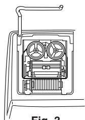
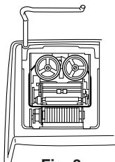
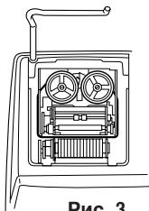
INK RIBBON REPLACEMENT
- Remove the paper roll from the calculator. (Tear the paper and remove it from the print mechanism by using 📂.)
- Turn the power off before replacing ribbon.
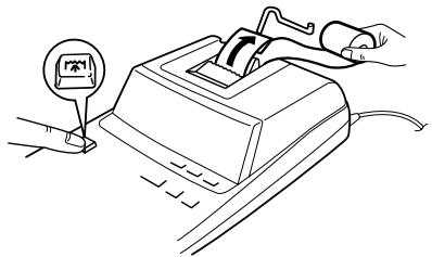
- Remove the printer cover. (Fig. 1)
- Remove the old ribbon by pulling it up.
- Insert the new ribbon.
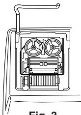
- With the black side of the ribbon facing upwards, place one of the reels on the reel shaft on the right. (Fig. 2) Make sure that the reel is securely in place.
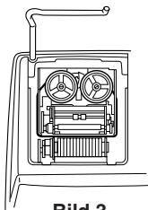
- Thread the ribbon around the outside of the metal guides. (Fig. 3)
- Take up any slack by manually turning one of the reels.
- Replace the printer cover. (Fig. 4)
- Replace the paper roll.
natural_image
Line drawing of a mechanical device with a lever and handle, no text or symbols presentFig. 1

natural_image
Two gray geometric shapes: a circle and an 'X' symbol, both on white background (no text or labels)
natural_image
Two abstract geometric shapes with spiral patterns, no text or symbols presentFig. 2
natural_image
Technical line drawing of a mechanical device with internal components and a handle (no text or symbols)Fig. 3

Fig. 4
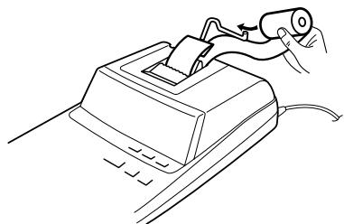
PAPER ROLL REPLACEMENT
Never insert paper roll if torn. Doing so will cause paper to jam.
Always cut leading edge with scissors first.
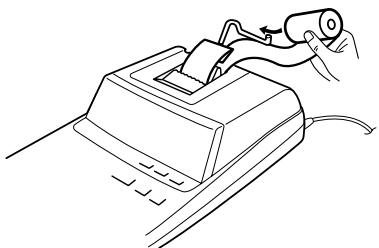
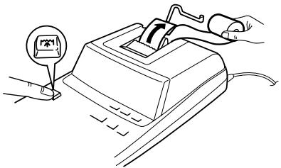
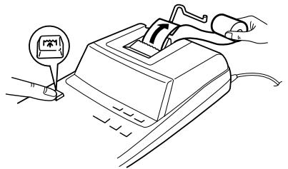
1) Insert the leading edge of the paper roll into the opening. (Fig. 1)
2) Turn the power on and feed the paper by pressing ⚠️. (Fig. 2)
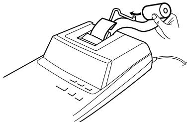
3) Insert the paper roll to the paper holder. (Fig. 3)
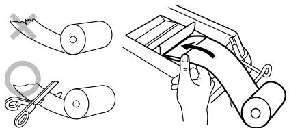
Fig. 1

Fig. 2
natural_image
Line drawing of a mechanical device with a lever and cable (no text or symbols)Fig. 3
DO NOT PULL PAPER BACKWARDS AS THIS MAY CAUSE DAMAGE TO PRINTING MECHANISM.
ERRORS
There are several situations which will cause an overflow or an error condition. When this occurs, "E" will be displayed. The contents of the memory at the time of the error are retained.
If an “0•E” is displayed at the time of the error, * must be used to clear the calculator. If an “E” with any numerals except zero is displayed, the error may be cleared with CE or and the calculation can still be continued.
Also, in rare cases, printing may stop midway and the indication “E” appear on the display. This is not a malfunction but is caused when the calculator is exposed to strong electromagnetic noise or static electricity from an external source. Should this occur, press the ☐ key and then repeat the calculation from the beginning.
Error conditions:
- Entry of more than 12 digits or 11 decimals. This error can be cleared with CE or →.
-
When the integer portion of an answer exceeds 12 digits.
-
When the integer portion of the contents of the memory or grand total memory exceeds 12 digits.
(Ex. *M 9999999999999 M+ 1 M+)
- When any number is divided by zero.
(Ex. 5 ÷ 0 ±)
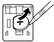
REPLACEMENT OF BATTERY FOR MEMORY PROTECTION
Time for battery replacement
Replace with a new battery once 2 year.
Method of battery replacement
Use one lithium battery (CR2032).
Note: When replacing the battery, the set tax / discount rate and the memory contents will be lost.
You may want to write down the tax / discount rate and other important numbers on a sheet of paper.
1) Turn the power switch "OFF" and unplug the power supply plug from the outlet.
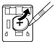
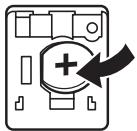
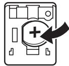
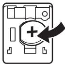
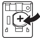
2) Remove the battery cover on the back of the unit. (Fig. 1)
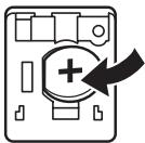
3) Remove the exhausted battery and install one new lithium battery. Wipe the battery well with a dry cloth and place the plus “+” side upward. (Fig. 2)
4) Replace the battery cover by reversing the removal procedure.
5) Press the RESET switch on the back of the unit (See page 13).
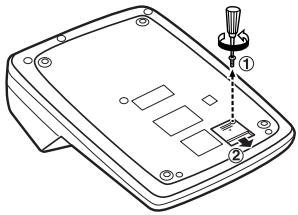
Fig. 1

natural_image
Diagram of a computer monitor with an icon and directional arrow, no text or symbols presentFig. 2
After battery replacement
- Connect the power supply plug to an outlet and turn the power switch "ON".
Check that "0." is displayed. If "0." is not displayed, remove the battery, reinstall it, and check the display again. - Reset the tax / discount rate.
- On the battery replacement date label found on the back of the unit, write down the month and year when the battery is replaced, as a reference for the next battery replacement.
Precautions on battery use
- Do not leave an exhausted battery in the equipment.
- Do not expose the battery to water or flame, and do not take it apart.
- Store batteries out of the reach of small children.
SPECIFICATIONS
Operating capacity: 12 digits Power supply: Operating: AC: 220V–230V, 50Hz Memory backup: 3V ≈ (DC) (Lithium battery CR2032 × 1)
Memory Protection Battery lifespan: Approx. 2 years. (tested and confirmed at 25^ C ( 77^ F); may change due to usage environment)
PRINTING SECTION
Printer: Mechanical printer Printing speed: Approx. 4.3 lines/sec. Printing paper: 57 mm(2-1/4") - 58 mm(2-9/32") wide 80 mm(3-5/32") in diameter (max.)
Operating temperature: 0^ C – 40^ C ( 32^ F – 104^ F) Power consumption: 67 mA
Dimensions:
$$ \begin{array}{l} \begin{array}{l} 2 2 2 \mathrm{mm(W)} \times 3 2 7 \mathrm{mm(D)} \ \times 7 8 \mathrm{mm(H)} \end{array} \ \begin{array}{l} 8 - 3 / 4" (W) \times 1 2 - 7 / 8" (D) \times \ 3 - 1 / 1 6" (H) \end{array} \ \end{array} $$
Weight:
$$ \begin{array}{l} \text { Approx.1.9kg(4.19lb.)} \ \text {(with battery)} \end{array} $$
Accessories:
1 lithium battery, 1 battery replacement date label (attached on the unit's back body), 1 paper roll, 1 ink ribbon (installed) and operation manual
WARNING
THE VOLTAGE USED MUST BE THE SAME AS SPECIFIED ON THIS CALCULATOR. USING THIS CALCULATOR WITH A VOLTAGE HIGHER THAN THAT SPECIFIED IS DANGEROUS AND MAY RESULT IN A FIRE OR OTHER TYPE OF ACCIDENT CAUSING DAMAGE. SHARP WILL NOT BE HELD RESPONSIBLE FOR ANY DAMAGE RESULTING FROM USE OF THIS CALCULATOR WITH OTHER THAN THE SPECIFIED VOLTAGE.
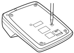
RESETTING THE UNIT
Strong impacts, exposure to electrical fields, or other unusual conditions may render the unit inoperative, and pressing the keys will have no effect. If this occurs, you will have to press the RESET switch on the bottom of the unit. The RESET switch should be pressed only when:
- an abnormal event occurs and all keys are disabled.
- you install or replace the battery.
Notes:
- Pressing the RESET switch will clear the stored tax / discount rate and other data stored in the memory.
- Use only a ballpoint pen to press the RESET switch. Do not use anything breakable or anything with a sharp tip, such as a needle.
- After pressing the RESET switch, connect the power supply plug to an outlet. Turn the power switch "ON" and check that "0." is displayed.
natural_image
Line drawing of a device with a screwdriver inserted into a rectangular base (no text or symbols)Abb. 1

natural_image
Diagram of a computer RAM module with an arrow indicating direction (no text or symbols)Abb. 2
natural_image
Line drawing of a mechanical component with an arrow indicating direction (no text or symbols)Abb. 1

natural_image
Two gray geometric shapes: a circle and an 'X' symbol, both on white background (no text or labels)
natural_image
Two abstract spiral-shaped outlines with no text or symbolsAbb. 2

natural_image
Technical line drawing of an electrical cabinet or motor housing with no visible text or symbolsAbb. 3
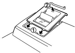
Abb. 4
ERSETZEN DER PAPIERROLLE
natural_image
Simple line drawing of a rolled paper or scroll with a wavy edge and a gray X mark (no text or symbols)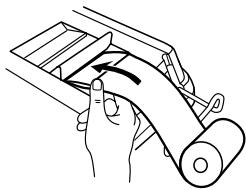
natural_image
Illustration of a hand holding a roller with an arrow indicating motion (no text or symbols)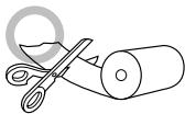
natural_image
Line drawing of scissors cutting a rolled paper with a circular mark overlay (no text or symbols)Abb. 1

natural_image
Line drawing of a hand pressing a button on a computer keyboard (no text or symbols present)Abb. 2
natural_image
Line drawing of a mechanical device with a hand holding a cylindrical component (no text or symbols)Abb. 3
Abb. 1
natural_image
Diagram of a computer mouse with a plus button and an arrow indicating action (no text or symbols)Abb. 2
natural_image
Line drawing of a device with a screwdriver inserted into a housing (no text or symbols)PRÉCAUTIONS
Fig. 1

natural_image
Diagram of a computer mouse with a plus button and an arrow indicating direction (no text or symbols)Fig. 2
"OFF": Mise hors tension.
REPLACEMENT DU RUBAN ENCREUR
natural_image
Simple line drawing of a mechanical device with a handle and internal component (no text or symbols)Fig. 1

natural_image
Two gray geometric shapes: a circle and an 'X' symbol, both on white background (no text or labels)
natural_image
Two abstract geometric shapes with spiral patterns, no text or symbols presentFig. 2

natural_image
Technical line drawing of a mechanical device with internal components and a handle (no text or symbols)Fig. 3
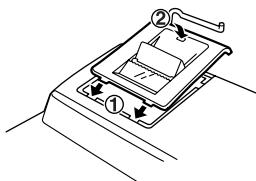
Fig. 4
REMPLACEMENT DU ROULEAU DE PAPIER
Fig. 1
natural_image
Line drawing of a hand pressing a button on a computer keyboard (no text or symbols present)Fig. 2

natural_image
Line drawing of a mechanical device with a hand holding a cylindrical component (no text or symbols)Fig. 3
NE PAS TIRER LE PAPIER EN ARRIÈRE, CAR CELA POURRAIT ENDOMMAGER LE MÉCANISME IMPRIMANT.
ERREURS
Fig. 1

natural_image
Diagram of a computer mouse with a plus sign and arrow indicating action (no text or symbols present)Fig. 2
222 mm (L) × 327 mm (P)
× 78 mm (H)
natural_image
Line drawing of a device with a screwdriver inserted into the top panel (no text or symbols)NOTAS AL MANEJARLA
Fig. 1

natural_image
Diagram of a computer RAM module with an arrow indicating direction (no text or symbols)Fig. 2
natural_image
Line drawing of a mechanical device with a handle and internal component (no text or symbols)Fig. 1

natural_image
Two gray geometric shapes: a circle and an 'X' symbol, both on white background (no text or labels)
natural_image
Two abstract geometric shapes with spiral patterns, no text or symbols presentFig. 2
natural_image
Technical line drawing of a mechanical device with internal components and a handle (no text or symbols)Fig. 3

Fig. 4
Fig. 1

Fig. 2

natural_image
Line drawing of a hand holding a cylindrical object above a mechanical device (no text or symbols)Fig. 3
Fig. 1

natural_image
Diagram of a computer mouse with a plus button and an arrow indicating action (no text or symbols)Fig. 2
natural_image
Line drawing of a device with a screwdriver inserted into the top panel (no text or symbols)NOTE INTRODUTTIVE
Fig. 1
natural_image
Diagram of a computer monitor with an icon and arrow indicating action (no text or symbols)Fig. 2
natural_image
Simple line drawing of a mechanical device with a handle and internal components (no text or symbols)Fig. 1

natural_image
Two gray geometric shapes: a circle and an 'X' symbol, on white background (no text or labels)
natural_image
Two abstract geometric shapes with spiral patterns, no text or symbols presentFig. 2
natural_image
Technical line drawing of a mechanical device with internal components and a handle (no text or symbols)Fig. 3

Fig. 4
SOSTITUZIONE DEL ROTOLO DI CARTA
Fig. 1
natural_image
Line drawing of a computer with hands operating it, no text or symbols presentFig. 2

natural_image
Line drawing of a mechanical device with a handle and cable, no text or symbols presentFig. 3
NON FAR RETROCEDERE IL MOVIMENTO DEL ROTOLO DI CARTA. CIÒ POTREBBE DANNEGGIARE IL MECCANISMO DI STAMPA.
ERRORI
(Es. *M 9999999999999 M+ 1 M+)
Fig. 1
natural_image
Diagram of a computer mouse with a plus button and an arrow indicating direction (no text or symbols)Fig. 2
222 mm (L) × 327 mm (P) × 78 mm (A)
natural_image
Line drawing of a device with a screwdriver inserted into the top panel (no text or symbols)OBSERVERA VID ANVÄNDNING
Fig. 1
natural_image
Diagram of a computer RAM module with a plus button and an arrow indicating direction (no text or symbols)Fig. 2
TANGENT FÖR TÖMNING AV HELA MINNET

TANGENT FÖR ÅTERKALLNING AV DELSVARSMINNET

TANGENT FÖR MINNESPLUS

TANGENT FÖR MINNESMINUS

TANGENT FÖR SKATTEPÅLÄGG

TANGENT FÖR SKATTEFRÅNDRAG

PROCENTTANGENT

TANGENT FÖR ICKE-ADDITION/DELSVAR:
natural_image
Line drawing of a mechanical device with a lever and handle, no text or symbols presentBild 1

natural_image
Two gray geometric shapes: a circle and an 'X' symbol, both on white background (no text or labels)
natural_image
Two abstract geometric shapes with spiral patterns, no text or symbols presentBild 2
natural_image
Technical line drawing of a mechanical device with internal components and a handle (no text or symbols)Bild 3
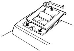
Bild 4
BYTE AV PAPPERSRULLEN
Bild 2
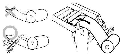
Bild 1

natural_image
Line drawing of a mechanical device with a hand holding a tool, no text or symbols presentBild 3
DRA ALDRIG PAPPERET BAKÅT DÅ DETTA KAN ORSAKA SKADOR PÅ SKRIVAR-MEKANISMEN.
FEL
BYTE AV BATTERI FÖR MINNESSKYDD
Tid för batteribyte
Fig. 1
natural_image
Diagram of a device with a plus sign and arrow indicating direction (no text or symbols)Fig. 2
After batteribyte
natural_image
Line drawing of a device with a screwdriver inserted into the top panel (no text or symbols)Afb. 1
natural_image
Diagram of a computer RAM module with a plus button and an arrow indicating direction (no text or symbols)Afb. 2
natural_image
Line drawing of a mechanical component with an arrow indicating direction (no text or symbols)Afb. 1

natural_image
Two gray geometric shapes: a circle and an 'X' symbol, on white background (no text or labels)
natural_image
Two abstract geometric shapes with spiral patterns, no text or symbols presentAfb. 2

natural_image
Technical line drawing of an electrical enclosure with internal components (no text or symbols)Afb. 3

Afb. 4
PAPIERROL VERVANGEN
Afb. 1
Afb. 2

natural_image
Line drawing of a mechanical device with a hand holding a cylindrical component (no text or symbols)Afb. 3
TREK HET PAPIER NIET IN ACHTERWAARTSE RICHTING TERUG AANGEZIEN DIT ZOU KUNNEN RESULTEREN IN BESCHADIGING VAN HET AFDRUKMECHANISME.
FOUTEN
Afb. 1
natural_image
Diagram of a computer monitor with an icon and directional arrow, no text or symbols presentAfb. 2
natural_image
Line drawing of a device with a screwdriver inserted into the top panel (no text or symbols)Fig. 1
natural_image
Diagram of a computer mouse with a plus button and an arrow indicating action (no text or symbols)Fig. 2
natural_image
Simple line drawing of a mechanical device with a handle and internal components (no text or symbols)Fig. 1

natural_image
Two gray geometric shapes: a circle and an 'X' symbol, both on white background (no text or labels)
natural_image
Two abstract geometric shapes with spiral patterns, no text or symbols presentFig. 2

natural_image
Technical line drawing of a mechanical device with internal components and a handle (no text or symbols)Fig. 3

Fig. 4
TROCA DO ROLO DE PAPEL
Fig. 1

natural_image
Line drawing of a computer with hands operating it, no text or symbols presentFig. 2

natural_image
Line drawing of a mechanical device with a hand holding a cable and a scroll, no text or symbols presentFig. 3
NÃO PUXE O PAPEL PARA TRÁS, POIS ISSO PODERIA CAUSAR DANOS AO MECANISMO DE IMPRESSÃO.
ERROS
Fig. 1
natural_image
Diagram of a computer mouse with a plus sign and arrow indicating action (no text or symbols)Fig. 2
natural_image
Line drawing of a device with a screwdriver inserted into the top panel (no text or symbols)KÄYTTÖHUOMAUTUKSIA
Kuva 1
natural_image
Diagram of a computer RAM module with an arrow indicating direction (no text or symbols)Kuva 2
natural_image
Line drawing of a mechanical component with an arrow indicating direction (no text or symbols)Kuva 1

natural_image
Two gray geometric shapes: a circle and an 'X' symbol, both on white background (no text or labels)
natural_image
Two abstract geometric shapes with spiral patterns, no text or symbols presentKuva 2
natural_image
Technical line drawing of an electrical enclosure or motor unit with no visible text or symbolsKuva 3

Kuva 4
PAPERIRULLAN VAIHTO
Kuva 1

natural_image
Line drawing of a hand pressing a computer with a circular icon showing a symbol (no text or labels present)Kuva 2
natural_image
Line drawing of a hand holding a cylindrical object above a mechanical device (no text or symbols)Kuva 3
ÄLÄ VEDÄ PAPERIA TAAKSEPÄIN, SILLÄ SE SAATTAA VAHINGOITTAA TULOSTUS-MEKANISMIA.
VIRHEET
Kuva 1


natural_image
Diagram of a computer monitor with an icon and arrow, no text or symbols presentKuva 2
Pariston vaihdosta
natural_image
Line drawing of a device with a screwdriver inserted into the top panel (no text or symbols)Рис. 1
natural_image
Diagram of a computer mouse with a plus sign and arrow indicating direction (no text or symbols)Рис. 2
natural_image
Simple line drawing of a mechanical device with a handle and internal components (no text or symbols)Рис. 1

natural_image
Two gray geometric shapes: a circle and an 'X' symbol, both on white background (no text or labels)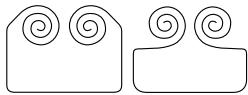
natural_image
Two abstract line drawings with spiral patterns, no text or symbols presentРис. 2
natural_image
Technical line drawing of a mechanical device with internal components and a handle (no text or symbols)Рис. 3

Рис. 4
ЗАМЕНА РУЛОНА БУМАГИ
Рис. 1

natural_image
Line drawing of a computer keyboard with hands operating it (no text or symbols present)Рис. 2

natural_image
Line drawing of a mechanical device with a hand holding a cylindrical component (no text or symbols)Рис. 3
Рис. 1
natural_image
Diagram of a computer mouse with a plus button and an arrow indicating direction (no text or symbols)Рис. 2
natural_image
Line drawing of a device with a screwdriver inserted into the top panel (no text or symbols)CALCULATION EXAMPLES
- Set the decimal selector as specified in each example.
The rounding selector should be in the "5/4" position unless otherwise specified. - The constant/add mode selector and grand total/ rate setting mode selector should be in the “•” position (off) unless otherwise specified.
- The print/item count mode selector should be in the "P" position unless otherwise specified.
- If an error is made while entering a number, press CE or and enter the correct number.
- Negative values are printed with “—” symbol in red.
RECHNUNGSBEISPIELE
B. 11.11 ÷ 77.77 =
$$ 2 2. 2 2 \div 7 7. 7 7 = $$
K·A

F63210

| (1) | (2) | (3) |
| 11.11 ÷ | 11.11 | 11 · 11 ÷ |
| 77.77 ± | 77 · 77 = K | |
| 0 · 143 * | ||
| 0.143 | ||
| 22.22 ± | 22 · 22 = K | |
| 0 · 286 * | ||
| 0.286 |
PERCENT / PROZENT / POURCENTAGE / PORCENTAJES / PERCENTUALE / PROCENTRÄKNING / PERCENTAGE / PORCENTAGEM / PROSENTTI / ПРОЦЕНТЫ
| (1) | (2) | (3) |
| 100 × | 100. | 100 · × |
| 25 % | 25 · % | |
| 25 · 00* | ||
| 25.00 |
| B. (123÷1368)×100= | F63210 |
| (1) | (2) | (3) |
| 123 + 1368 % | 123. | 123 ÷1·368 %8·99* |
| 8.99 |
ADD-ON AND DISCOUNT / AUFSCHLAG UND ABSCHLAG / MAJORATION ET RABAIS / RECARGOS Y DESCUENTOS / MAGGIORAZIONE E SCONTO / TILLÄGG OCH RABATT / OPSLAG/KORTING / ACRÉSCIMO E DESCONTO / LISÄYS/VÄHENNYS / НАЦЕНКА И СКИДКА
A. 5% add-on to 100. / Ein Aufschlag von 5% auf 100. / Majoration de 5% de 100. / Un 5% de recargo sobre 100. / Maggiorazione del 5% su 100. / 5% tillägg på 100. / Een opslag van 5% op 100. / Um acréscimo de 5% sobre 100. / 5% lisätään 100:aan / 5% naценka na 100.
F63210
| (1) | (2) | (3) |
| 100 × 5 | 100. | 100 × 5 % |
| 5 00 Increased amount\ Erhöhung\ Majoration\ Incremento\ Importo incrementato\ Tillagt belopp\ Extra bedrag\ Quantia aumentada\ Lisätty määrä\ Величина наценки . | ||
| 105 00 * New amount\ Neuer Betrag\ Total majoré\ Nueva cantidad\ Nuovo importo\ Nytt belopp\ Nieuwe bedrag\ Nova quantia\ Uusi määrä\ Новая сумма . | ||
| 105.00 |
B. 10% discount on 100. / Ein Abschlag von 10% auf 100. / Rabais de 10% sur 100. / Un 10% de descuento sobre 100./Sconto del 10% su 100. / 10% rabatt på 100. / Een korting van 10% op 100. / Desconto de 10% de 100. / 10% alennus 100:sta. / 10% скидка со 100.
| (1) | (2) | (3) |
| 100 × 10 +/- MU | 100. | 100 ×- 10 %{DiscountAbschlagRemiseDescuentoScontoRabattKortingDescontoAlennusСкидка |
| - 10 · 00{Net amountNettobetragMontant netCantidad netaNuovo importoNettobeloppNettobedragQuantia líquidaUusi määräНовая сумма | ||
| 90.00 |
MARKUP AND MARGIN / GEWINNAUFSCHLAG UND GEWINNSPANNE / HAUSSE ET MARGE BÉNÉFICIAIRE / INCREMENTO PORCENTUAL Y MARGEN / MARGINE LORDO E MARGINE NETTO / PÅSLAG OCH MARGINAL / PROCENTUELE VERHOGING EN WINSTMARGE / REMARCAÇÃO PARA CIMA E MARGEM / KATE- JA VOITTOPROSENTTI / НАЦЕНКА И ПРИБЫЛЬ
Markup and Profit Margin are both ways of calculating percent profit.
– Profit margin is percent profit vs. selling price.
– Markup is percent profit vs. cost.
- Cost is the cost.
– Sell is the selling price.
– GP is the gross profit.
- Mkup is the percent profit based on cost.
– Mrgn is the percent profit based on selling price.
- "Cost" is de inkoopprijs.
- "Sell" is de verkoopprijs.
- "GP" is de brutowinst.
| Cost | Sell | GP | Mkup | Mrgn |
| 200 | 250 | $50 | 25% | 20% |
F63210
| (1) | (2) | (3) |
| 200 ÷ 20 | 200. | 200 · ÷ Cost20 · %M Mrgn250 · 00* Sell50 · 00 GP GP |
| 50.00 |
PERCENT CHANGE / ÄNDERUNG DER PROZENTE / VARIATION EN POUR CENT / CAMBIO PORCENTUAL / VARIAZIONE IN PERCENTUALE / ÄNDRING I PROCENT / PROCENTUELE VERANDERING / VARIAÇÃO PERCENTUAL / PROSENTTIMUUTOS / ПРОЦЕНТНОЕ ИЗМЕНЕНИЕ
- Calculate the dollar difference (a) and the percent change (b) between two yearly sales figures \1,500 in one year and \1,300 in the previous.
- Berechne den Unterschied in Dollar (a) und die Änderung der Prozente (b) zwischen zwei Jahresumsätzen von \1.500 in einem Jahr und \1.300 im Vorjahr.
- Calculer la différence en dollars (a) et la variation en pour cent (b) entre deux prix. 1.500 \pour cette année et 1.300 \ pour l'année précédente.
- Calcular la diferencia en dólares (a) y el cambio porcentual (b) entre dos cifras de ventas anuales, \1.500 en un año y \1.300 en el año anterior.
- Calcolare la differenza in dollari (a) e la variazione in percentuale (b) tra due cifre delle vendite pari a 1500\in un anno e 1300\ in quello precedente.
-
Beräkna skillnaden i dollar (a) och ändringen i procent (b) mellan två årliga försäljningssiffror på \1.500 det ena året och \1.300 året innan.
-
Bereken het verschil in dollars (a) en de procentuele verandering (b) tussen twee jaarlijkse verkoopcijfers: \1.500 in een bepaald jaar en \1.300 het jaar ervoor.
- Calcule a diferença em dólares (a) e a variação percentual (b) entre duas vendas anuais de \1.500 em um ano e de \1.300 no ano anterior.
- Laske ero dollareina (a) ja muutos prosentteina (b) kahden vuosittaisen myyntiluvun välillä, 1500\yhtenä vuonna ja 1300\ edellisenä.
- Вычислить разность в долларах (a) и процентное изменение (b) между двумя численными значениями годовых продаж \1500 в одном году и \1300 в предыдущем.
F63210
| (1) | (2) | (3) |
| 1500 ± | 1,500.00 | 1·500·00 + |
| 1300 — = MU | 200.00 | 1·300·00 –200·00 * (a)15·38 %C (b) |
| 15.38 |
ITEM COUNT CALCULATION / BERECHNUNG MIT DEM POSTENZÄHLER / CALCUL DE COMPTE D'ARTICLES / CÁLCULO DE CUENTA DE ARTÍCULOS / CALCOLO CONTEGGIO VOCI / RÄKNING MED POSTRÄKNAREN / REKENEN MET DE POSTENTELLER / CÁLCULO DA CONTAGEM DE ITENS / TEKIJÄLASKURI / ВЫЧИСЛЕНИЯ С ПОДСЧЕТОМ КОЛИЧЕСТВА ОПЕРАЦИЙ
| Bill No.Rechnung Nr.Facture n°N° de facturaNumero di fatturaFakturanr.Rekeningnr.N° da faturaLaskunr.Cчет No. | Number of billsAnzahl der RechnungenNbre de facturesCantidad de facturasNumero delle fattureAntal fakturorAantal rekeningenNúmero de faturasLaskujen lukumääräКоличество счетов | AmountBetragMontantImporteImportoBeloppBedragQuantiaMääräСумма |
| 1 | 1 | 100.55 |
| 2 | 1 | 200.00 |
| 3 | 1 | 200.00 |
| 4 | 1 | 400.55 |
| 5 | 1 | $500.65 |
| Total / Summe / TotalTotal / Totale / SvarTotaal / Total / Summa /Bcero | (a) | (b) |
OFF • P P•IC
F63210


| (1) | (2) | (3) | ||
| * | ||||
| 100.55 | ± | 100.55 | 100 · 55 + | |
| 200 | ± | 300.55 | 200 · 00 + | |
| ± | 500.55 | 200 · 00 + | ||
| 400.55 | ± | 901.10 | 400 · 55 + | |
| 500.65 | ± | 1,401.75 | 500 · 65 + | |
| * | 005 | (a) | ||
| 1,401 · 75 * | (b) | |||
| 1,401.75 | ||||
GRAND TOTAL / ENDSUMME / TOTAL GÉNÉRAL / TOTAL GLOBAL / TOTALE GENERALE / SLUTSVAR / EINDTOTAAL / TOTAL GERAL / KOKONAISSUMMA / ОБЩАЯ СУММА
$$ 1 0 0 + 2 0 0 + 3 0 0 = $$
$$ +) 5 0 0 - 6 0 0 + 7 0 0 = $$
EXAMPLE 1: Set a 5% tax rate. Calculate the total amount for adding a 5% tax to \$800.
This equipment complies with the requirements of Directives 89/336/EEC and 73/23/EEC as amended by 93/68/EEC.