
LL-151-3D - Calculator SHARP - Free user manual and instructions
Find the device manual for free LL-151-3D SHARP in PDF.

| Product Type | 3D LCD Monitor |
| Brand | SHARP |
| Model | LL-151-3D |
| Screen Diagonal | 38 cm (15 inches) |
| Maximum Resolution | 1024 x 768 (XGA) |
| Displayable Colors | 16.19 million (6 bit + FRC) |
| Brightness (2D / 3D mode) | 370 cd/m² / 140 cd/m² |
| Contrast Ratio | 500:1 |
| Viewing Angle (Horizontal / Vertical) | 130° / 115° |
| Weight (with stand / without stand) | 5.3 kg / 3.4 kg |
| Power Supply | 100-240 V AC, 50/60 Hz (power adapter NL-A56J) |
| Power Consumption (max / standby) | 29 W / 2 W |
| Video Inputs | DVI-I (digital and analog) |
| Audio Input | Mini-stereo jack |
| Headphone Output | Mini-stereo jack |
| USB Port | Yes (for 3D display) |
| Built-in Speakers | 2 x 1 W |
| Main Features | Glasses-free 3D display, 2D/3D switching, height/tilt adjustment, adjustable backlight, settings lock, VESA compatibility (75x75 mm) |
| Maintenance and Cleaning | Unplug before cleaning. Use a soft, dry cloth. Do not use solvent, alcohol, or glass cleaner. |
| Safety | Do not expose to moisture, direct sunlight, or high temperatures. Do not block ventilation openings. Unplug if not used for a long time. |
| Spare Parts and Repairability | The backlight has a limited lifespan. Contact an authorized Sharp repair center for replacement. Use only the supplied power adapter. |
Frequently Asked Questions - LL-151-3D SHARP
User questions about LL-151-3D SHARP
0 question about this device. Answer the ones you know or ask your own.
Ask a new question about this device
Download the instructions for your Calculator in PDF format for free! Find your manual LL-151-3D - SHARP and take your electronic device back in hand. On this page are published all the documents necessary for the use of your device. LL-151-3D by SHARP.
USER MANUAL LL-151-3D SHARP
natural_image
Line drawing of a flat-screen computer monitor with a circular base (no text or symbols)Notice for Users in the USA 3
Notice for Users in Europe 4
Notice for Users in the UK 5
Notice for Users in Australia 5
English 7
Deutsch 35
Français 63
Italiano 91
Español.... 119
IMPORTANT:
To aid in reporting in case of loss or theft, please record the monitor's model and serial numbers in the space provided. The numbers are located on the rear of the monitor.
Model No.:
Serial No.:
FCC Statement
WARNING – FCC Regulations state that any unauthorized changes or modifications to this equipment not expressly approved by the manufacturer could void the user's authority to operate this equipment.
Note: This equipment has been tested and found to comply with the limits for a Class B digital device pursuant to Part 15 of the FCC Rules.
These limits are designed to provide reasonable protection against harmful interference in a residential installation. This equipment generates, uses and can radiate radio frequency energy and, if not installed and used in accordance with the instructions, may cause harmful interference to radio communications. However, there is no guarantee that interference will not occur in a particular installation. If this equipment does cause harmful interference to radio or television reception, which can be determined by turning the equipment off and on, the user is encouraged to try to correct the interference by one or more of the following measures:
- Reorient or relocate the receiving antenna.
- Increase the separation between the equipment and receiver.
- Connect the equipment into an outlet on a circuit different from that to which the receiver is connected.
- Consult the dealer or an experienced radio/TV technician for help.
Use nothing but the included cables and AC cord to insure compliance with FCC regulation for Class B computing equipment.
Declaration of Conformity
SHARP LCD Color Monitor LL-151-3D
This device complies with part 15 of the FCC rules. Operation is subject to the following conditions: (1) this device may not cause harmful interference, and (2) this device must accept any interference received, including interference that may cause undesired operation.
Responsible Party: SHARP ELECTRONICS CORPORATION
Sharp Plaza, Mahwah, New Jersey 07430
TEL: 1-800-BE-SHARP

* As an ENERGY STAR® Partner, SHARP has determined that this product meets the ENERGY STAR® guidelines for energy efficiency.
This product utilizes tin-lead solder, and fluorescent lamp containing a small amount of mercury. Disposal of these materials may be regulated due to environmental considerations. For disposal or recycling information, please contact your local authorities or the Electronics Industries Alliance: www.eiae.org
Notice for Users in Europe
This equipment complies with the requirements of Directives 89/336/EEC and 73/23/EEC as amended by 93/68/EEC.
The wires in this mains lead are coloured in accordance with the following code:
GREEN-AND-YELLOW : Earth
BLUE : Neutral
BROWN : Live
As the colours of the wires in the mains lead of this apparatus may not correspond with the coloured markings identifying the terminals in your plug proceed as follows:
- The wire which is coloured GREEN-AND-YELLOW must be connected to the terminal in the plug which is marked by the letter E or by the safety earth 12 or coloured green or green-and-yellow.
- The wire which is coloured BLUE must be connected to the terminal which is marked with the letter N or coloured black.
- The wire which is coloured BROWN must be connected to the terminal which is marked with the letter L or coloured red.
Ensure that your equipment is connected correctly. If you are in any doubt consult a qualified electrician.
"WARNING: THIS APPARATUS MUST BE EARTHED."
Notice for Users in Australia
Service Inquiries
Please contact your dealer for service if required or contact Sharp Corporation of Australia on 1 300 13 50 22 for referral to your nearest Sharp authorized Service Center.
Table of Contents
Tips and safety precautions....8
Product description 10
Angle adjustment, height adjustment 11
Connecting the monitor and turning the monitor on and off.... 12
Connecting the monitor to a computer 13
Connection of headphones (commercially available) 14
Connecting the monitor to a power source 14
Turning the power on 15
Turning the power off 15
Adjusting the screen display and speaker volume.... 16
Adjusting the backlight.... 16
Adjusting the speaker volume 16
Adjusting the screen display 17
Automatic screen adjustment (When using an analog signal) 17
Manual screen adjustment.... 18
Preparation for 3D display....21
How to install SHARP Stereo Display 21
Supplied software 22
Displaying 3D images 23
Monitor care 24
Monitor care 24
Storage 24
Troubleshooting 24
Specifications 26
Installing set-up information and the ICC profile (For Windows) 30
Information about the ColorSync profile (For MacOS) 33
Instructions for attaching a VESA-compliant arm 34
Tips and safety precautions
- The TFT color LCD panel used in this monitor is made with the application of high precision technology. However, there may be minute points on the screen where pixels never light or are permanently lit. Also, if the screen is viewed from an acute angle there may be uneven colors or brightness. Please note that these are not malfunctions but common phenomena of LCDs and will not affect the performance of the monitor.
- Do not display a still picture for a long period, as this could cause a residual image.
- If the brightness is adjusted to the minimum setting it may be difficult to see the screen.
- The quality of the computer signal may influence the quality of the display. We recommend using a computer able to emit high quality video signals.
- Never rub or tap the monitor with hard objects.
- Please understand that SHARP Corporation bears no responsibility for errors made during use by the customer or a third party, nor for any other malfunctions or damage to this product arising during use, except where indemnity liability is recognized under law.
- This monitor and its accessories may be upgraded without advance notice.
- Be sure to observe the following when viewing a stereoscopic (3D) display.
- If you feel eyestrain, headache, symptoms similar to motion sickness, or other unusual symptoms, immediately stop looking at the screen and take a rest. If the symptom does not subside after a rest, consult a doctor.
- If you continue looking at the 3D display for a long time, every 30 minutes give your eyes a rest by taking a break of about 30 minutes.
- Do not allow children under the age of 16 to view the 3D display in order to protect the development of their eyes.
Location
- Do not use the monitor where ventilation is poor, where there is a lot of dust, where humidity is high, or where the monitor may come into contact with oil or steam, as this could lead to fire.
- Ensure that the monitor does not come into contact with water or other fluids. Ensure that no objects such as paper clips or pins enter the monitor as this could lead to fire or electric shock.
- Do not place the monitor on top of unstable objects or in unsafe places. Do not allow the monitor to come into contact with strong shocks or vibrations. Causing the monitor to fall or topple over may damage it.
- Do not use in places where the monitor will be subject to direct sunlight, near heating equipment or anywhere else where there is likelihood of high temperature, as this may lead to generation of excessive heat and outbreak of fire.
- When carrying the monitor, firmly grasp both the display and stand section. If the monitor is lifted by the display only, the stand may abruptly pop out or move, and this could lead to injury. If the monitor is inclined, the stand may move and cause injury.
- Be careful not to allow your fingers to be pinched between the display and stand. (Especially in the area of attachment.)
Tips and safety precautions
The Power Cord
- Do not damage the power cord nor place heavy objects on it, stretch it or over bend it. Also, do not add extension cords. Damage to the cord may result in fire or electric shock.
- Use only the power cord supplied with the monitor.
- Insert the power plug directly into the AC outlet. Adding an extension cord may lead to fire as a result of overheating.
- Do not remove or insert the power plug with wet hands. Doing so could result in electric shock.
Use of AC adapter
- Do not use the AC adapter for other than the specified equipment.
- Unplug the AC adapter if it is not used for long time.
- Do not place any objects on the AC adapter.
- Do not use the AC adapter outdoors.
- Do not attempt to repair the AC adapter if it is broken or malfunctioning. Refer the servicing to the service representative.
- Do not try to open the AC adapter.
- Do not use water or wet cloth for cleaning the AC adapter.
Monitor and accessory checklist
- Please check that the following items are included in the package.
- LCD monitor (1)
- AC adapter (1) (model name: NL-A56J)
- Power cord (1)
- Digital signal cable (1) (model name: QCNW-1088MPZZ)
- Analog signal cable (1) (model name: QCNW-1122MPZZ)
- Audio cable (1) (model name: QCNW-1124MPZZ)
- USB cable (1) (model name: QCNW-1123MPZZ)
- CD-ROM (1)
- Operation manual (1)
Notes:
- Use only the cables supplied with the monitor.
- You are advised to retain the carton in case the monitor needs to be transported.
- Sharp Corporation holds authorship rights to the Utility program. Do not reproduce it without permission.
- The shape of the supplied accessories may not be exactly same as shown in this manual.
Manual Scope
- In this manual, Microsoft Windows XP will be referred to as "Windows XP", Microsoft Windows Millennium as "Windows Me", Microsoft Windows 2000 as "Windows 2000", Microsoft Windows 98 as "Windows 98", Microsoft Windows 95 as "Windows 95", and Microsoft Windows Version 3.1 as "Windows 3.1". When there is no need to distinguish between programs, the term "Windows" will be used.
- Microsoft and Windows are registered trademarks of Microsoft Corporation.
- Macintosh is a registered trademark of Apple Computer, Inc.
- All other brand and product names are trademarks or registered trademarks of their respective holders.
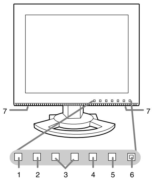
- MENU button ...... This button is used to pop-up, select and close the OSD (On Screen Display) Menu.
- ▼ button.... This button is used to select menu options when the OSD Menu is displayed.
- ◀▶ buttons ...... When the OSD Menu is displayed:
These buttons are used to select an option or adjust the value of the selected option.
When the OSD Menu is not displayed:
These buttons are used to adjust backlight brightness and speaker volume.
- 3D button ...... Switches display between 2D and 3D mode.
- Power button.... Pressing this button turns the power on.
Press the button again to turn the power off.
- Power LED ...... This LED is lit green when in 2D mode, blue when in 3D mode, and orange when in power-saving mode.
- Speakers......Audio entering via the external device connected to the monitor can be heard.
- Power terminal
- DVI-I input terminal .... The computer's digital RGB output terminal or analog RGB output terminal can be connected here.
For a digital signal input: It can be connected to a computer with a DVI-compatible output terminal (DVI-D 24 pin or DVI-I 29 pin) and which has XGA output ability. Depending on the computer to be connected, correct display may or may not be possible.
-
Security lock anchor ....By connecting a security lock (commercially available) to the security lock anchor, the monitor is fixed so that it cannot be transported. The security slot works in conjunction with Kensington Micro Saver Security Systems.
-
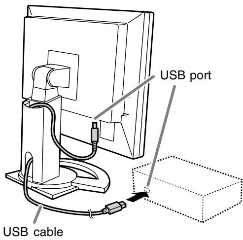
USB port (for 3D display) ...... Connects to the computer's USB port using the supplied USB cable.
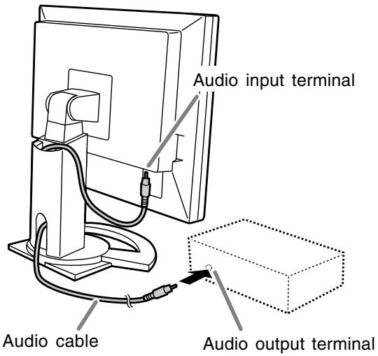
- Audio input terminal ...... A computer's audio output terminal can be connected here. The audio cable included should be used.
- Headphone terminal ...... Headphones (commercially available) can be connected here.
- Ventilation openings...... Never block the ventilation openings as this may lead to overheating inside the monitor and result in malfunction.
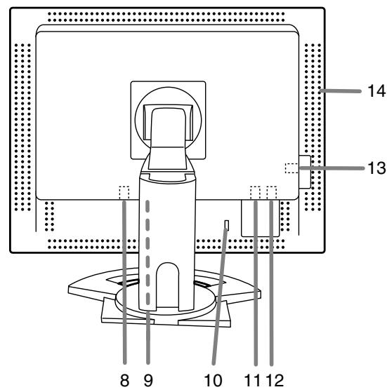
Angle adjustment, height adjustment
CAUTION!
- Be sure to hold both sides of the monitor when adjusting the viewing angle. The LCD panel used in this monitor is made of glass. Pressure from hands on the LCD panel could cause damage.
- Be careful not to allow your fingers to be pinched.
Angle adjustment
Adjust to an easy to view angle.
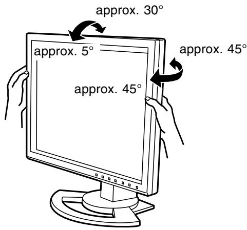
Height adjustment
Adjust to an easy to view height.
Connecting the monitor and turning the monitor on and off
CAUTION!
- When connecting, ensure that both the monitor and computer are switched off.
- Be careful not to over bend the cable or add extension cords as this could lead to a malfunction.
Cable storage
If necessary, excess cable can be housed in the stand.
- Remove the cover.
Gently pull the top of the cover towards yourself.
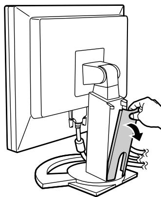
natural_image
Illustration of a hand using a computer monitor to press or install a device (no text or symbols visible)- Run cable along the back of the stand.
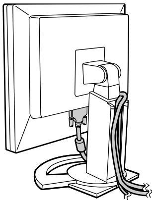
natural_image
Line drawing of a computer monitor mounted on a stand with cables, no text or symbols present- Refit the cover.
Be careful not to pinch the cable.
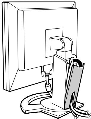
natural_image
Line drawing of a computer monitor mounted on a stand with cables, no text or symbols present- If the cover is hard to refit, do not force it. Check whether cables are trapped.
Connecting the monitor and turning the monitor on and off
Connecting the monitor to a computer
Digital connection
Connect the supplied digital signal cable to the digital RGB output terminal of the computer.
- The monitor has an input for connecting to a computer with a DVI-compatible output connector (DVI-D 24 pin or DVI-I 29 pin) and XGA output capability. (Depending on the type of computer to be connected, the display may not work correctly.)
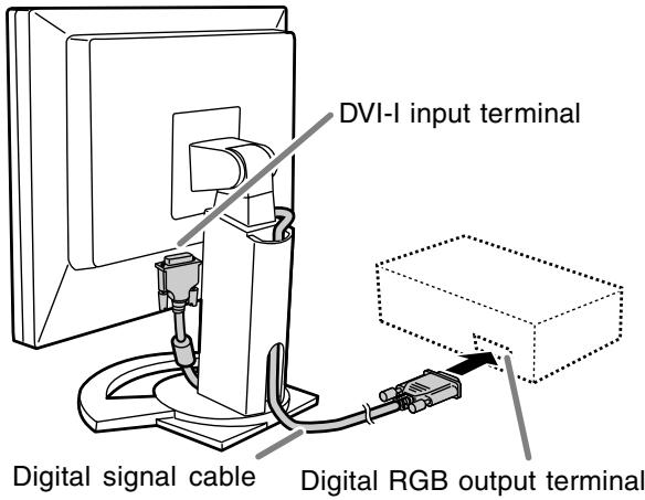
- Paying attention to connector direction, firmly insert the signal cable vertically into the connector, and then tighten the screws at both sides.
Set the monitor as follows when establishing a digital connection with a Power Mac using an ADC-DVI adapter made by Belkin. (Operation has been checked with the Power Mac G4 M7627J/A.)
- Perform settings with the Power Mac power supply off.
- Connect the AC adapter and the power cord.
- Press the ◀ button and ▶ button simultaneously, and while doing this press the power button (i.e. turn the power on).

- Set to [ON] with the ◀▶ buttons.
- Do not set to [ON] if you are not using a Belkin ADC-DVI adapter, as this may result in incorrect display.
- Press the MENU button.
This completes setting.
Analog connection
Connect the supplied analog signal cable to the analog RGB output terminal of the computer.
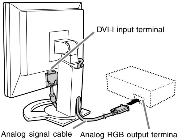
- Paying attention to connector direction, firmly insert the signal cable vertically into the connector, and then tighten the screws at both sides.
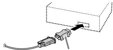
If connecting to a D-sub 15 pin 2 row Apple Power Macintosh, attach a Macintosh conversion adapter (commercially available) to the analog signal cable.
natural_image
Diagram of a cable connector inserted into a rectangular box, showing wiring and a plug (no text or symbols)Macintosh conversion adapter
Connecting the monitor and turning the monitor on and off
Connect the supplied audio cable
When the supplied audio cable is connected to the audio output terminal of the computer, the sound of the connected computer is output from the monitor speakers. You can also use the headphone jack of the display.
Connection of headphones (commercially available)
Headphones (commercially available) can be connected.
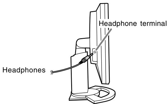
Notes:
- When the headphones are connected, no sound can be heard from the monitor speakers.
- Use headphones with a cable less than 3 m in length.
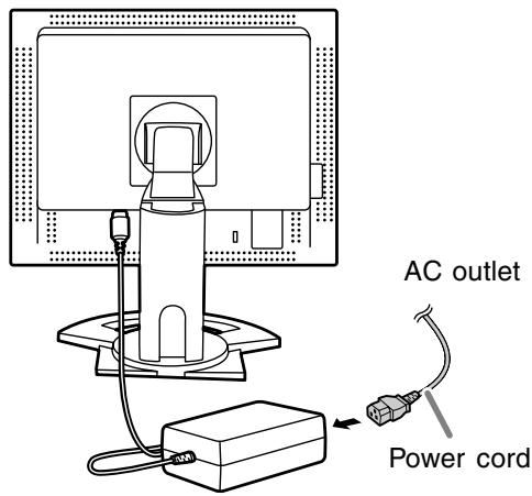
Connecting the monitor to a power source
CAUTION!
- Always use the AC adapter that came with the monitor.
- Connect the AC adapter to the power terminal.
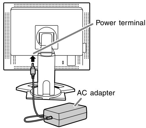
- Plug the power cord into the AC adapter and then place the power plug into an AC outlet.
Connecting the monitor and turning the monitor on and off
Turning the power on
- Press the monitor's power button.
- Turn on the computer.
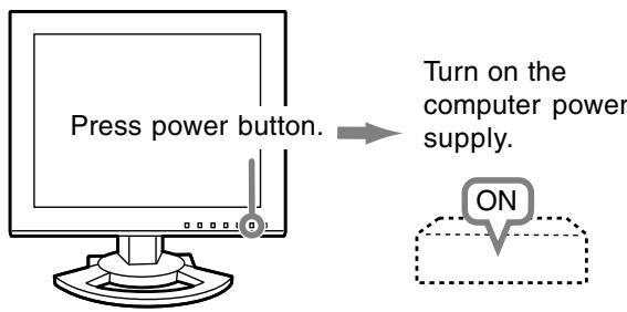
When a signal is input from the computer, the power LED lights up green, and the screen is displayed. (After power is turned on, it may take a little time until the screen is displayed.)
Turning the power off
- Turn the computer off.
- Press the monitor's power button.
The power LED will disappear.
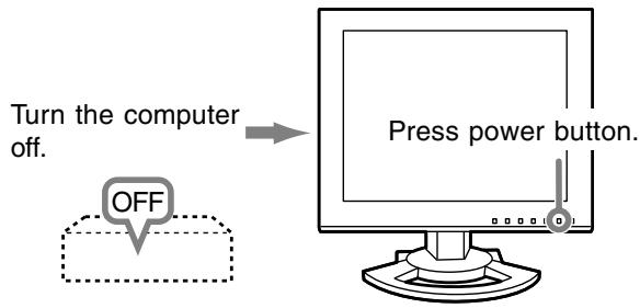
If the monitor is not going to be used for a long period of time, be sure to unplug it from the AC outlet.
Notes:
- When using an analog signal, perform an automatic screen adjustment under the following conditions (p.17):
- Using the monitor for the first time.
- After having changed the system settings during use.
- When using the monitor with a digital connection, automatic screen adjustment is unnecessary.
- Depending on the type of computer or OS, you may need to install the monitor set-up information on your system. (p.30)
- When connecting to a notebook, if the notebook computer's screen is set to display at the same time, the MS-DOS screen may not display properly. In this case, change the setting to display only the LCD monitor.
Adjusting the screen display and speaker volume
For digital signal
The monitor can generally be used without adjustment. If necessary perform manual adjustment. (p.18)
For analog signal
- First perform an automatic adjustment. (p.17)
- Perform manual adjustment where necessary. (p.18)
Note:
- All adjustments will be saved even after turning the power off.
Resetting all adjustment values
All adjustment values can be returned to their original ex-factory values in one command.
- Turn off the monitor power.
- Press the MENU button and the ▼ button simultaneously, and while doing this press the power button (i.e. turn the power on). Continue to press the buttons until [ALL RESET] appears on the screen. Reset is complete when the displayed message disappears.
Notes:
- While [ALL RESET] is displayed, the control buttons are disabled.
- It is not possible to reset values when the adjustment lock is in place. Remove the adjustment lock before attempting to operate control buttons.
ADJUSTMENT Menu reset
Settings of items in the ADJUSTMENT Menu (CLOCK, PHASE, H-POS, V-POS) can be returned to their original ex-factory values.
- Turn on the monitor power.
- Press the MENU button and the ◀ button simultaneously. When [RESET] appears on the screen, the reset is complete.
Notes:
- While [RESET] is displayed, the control buttons are disabled.
- It is not possible to reset values when the adjustment lock is in place. Remove the adjustment lock before attempting to operate control buttons.
Adjustment lock function
By disabling the control buttons (i.e. setting the lock) any attempted changes to adjusted values will be voided.
- Turn off the monitor power.
-
While pressing the MENU button, press the power button (i.e. turn the power on).
Continue to press the buttons until [LOCK ADJUSTMENT?] appears on the screen. -
Press the ▶ button.
Note:
- When the lock is in place, all buttons other than the power button are disabled.
Adjustment lock release
- Turn off the monitor power.
-
While pressing the MENU button, press the power button (i.e. turn the power on). Continue to press the buttons until [UNLOCK ADJUSTMENT?] appears on the screen.
-
Press the ▶ button.
Adjusting the backlight
- Without the OSD Menu being displayed, press the ◀ or the ▶ button.
- Check that [BRIGHT] is selected. If it is not selected, press the ▼ button and select [BRIGHT].
![VOLUME 18 BRIGHT 31 SELECT...[▼]](/content/2019/11/78774/images/771656ee9266829643f0602ca49d00d516fd4312d41ecbd944530c7b56ca290d.jpg)
- Adjust by pressing the ◀ button (darker) or ▶ button (lighter).
Note:
- On Screen display for adjustment disappears several seconds after the last operation.
Adjusting the speaker volume
- Without the OSD Menu being displayed, press the ◀ or the ▶ button.
- Check that [VOLUME] is selected. If it is not selected, press the ▼ button and select [VOLUME].
![VOLUME 18 BRIGHT 31 SELECT...[▼]](/content/2019/11/78774/images/d4891d21fa411ec7c78946fa80a1fc66d34fdf3fc38ab85f0c863b71bcbfd0c9.jpg)
- Adjust by pressing the ◀ button (decrease) or ▶ button (increase).
Note:
- On Screen display for adjustment disappears several seconds after the last operation.
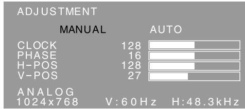
Automatic screen adjustment (When using an analog signal)
Options in the ADJUSTMENT Menu can be adjusted automatically (CLOCK, PHASE, H-POS, V-POS).
Notes:
- When setting up this monitor for the first time or after having changed an aspect of the current system, perform an automatic screen adjustment before use.
- Automatic screen adjustment is unnecessary when the monitor is used with a digital connection. Perform manual screen adjustment when necessary. (p.18)
Screen display for adjustment
First display an image that makes the entire screen light.
If you are using Windows, you can use the Adjustment Pattern on the supplied CD-ROM.
Opening the Adjustment Pattern (for Windows)
This explanation is for Windows 95/98/2000/Me/XP, and assumes that the CD-ROM drive is "D" drive.
- Load the supplied CD-ROM into the CD-ROM drive of the computer.
- Open [My Computer] and select CD-ROM. If using Windows 3.1, open [File Manager] and choose "D" drive.
- Double click on [Adj_uty.exe] to run the Adjustment Program. The Adjustment Pattern will appear.
Adjustment Pattern
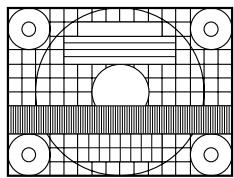
natural_image
Abstract geometric pattern with concentric circles and a central semicircle on a grid background (no text or symbols)After completing the adjustments, press the computer's [Esc] key to exit the Adjustment Program.
Note:
- If your computer's display mode is set to 65K colors, you may see the different color levels in each color pattern or the gray scale may look colored. (This is due to the specification of the input signal and is not a malfunction.)
Adjusting the screen automatically
- Press the MENU button. The ADJUSTMENT Menu will be displayed.
- Press the ▶ button.
The screen will become dark and [ADJUSTING] will be displayed. After a few seconds the ADJUSTMENT Menu will return. (The automatic adjustment is now complete.)
- Press the MENU button 4 times to make the OSD (On Screen Display) Menu disappear.
Notes:
- In most cases automatic adjustment is sufficient.
- It may not be possible to achieve correct adjustment with the first automatic adjustment. In such a case, try repeating the automatic adjustment 2 or 3 times.
- If necessary due to any of the following, manual adjustments (p.18) can be performed after the automatic adjustment.
- When further fine adjustment is needed.
- When [OUT OF ADJUST] is displayed. (When the screen displays an entirely dark image, the automatic screen adjustment may be disabled. When making an automatic adjustment, be sure to either use the Adjustment Pattern or try displaying an image that makes the entire screen very bright.)
- Automatic adjustment may not be achieved correctly depending on what is displayed on the screen - moving pictures or the MS-DOS prompt etc.
Adjusting the screen display
Manual screen adjustment
- Display an image that makes the entire screen light. (p.17)
- Display the OSD Menu by pressing the MENU button.
ADJUSTMENT Menu
Select the option by pressing the ▼ button.
GAIN CONTROL Menu
Select the option by pressing the ▼ button.
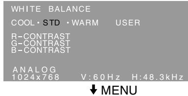
WHITE BALANCE Menu
Select the option by pressing the ◀ or the ▶ button.
MODE SELECT Menu
Select the option by pressing the ▼ button.
Notes:
- When the monitor is used with a digital connection, ADJUSTMENT and GAIN CONTROL Menu adjustments are not necessary.
- The OSD Menu automatically disappears approximately 30 seconds after the last command.
- This chapter provides the procedure how to adjust the screen by using Adjustment Pattern (for Windows).
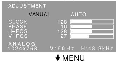
ADJUSTMENT Menu
When the monitor is used with a digital connection, this menu adjustment is not necessary.
AUTO
When [AUTO] is selected with the ▶ button, the [CLOCK], [PHASE], [H-POS] and [V-POS] settings are automatically adjusted.
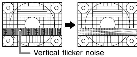
CLOCK
The figure below demonstrates how to adjust so that vertical flicker noise is not emitted.
(<► buttons)
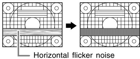
PHASE
The figure below demonstrates how to adjust so that horizontal flicker noise is not emitted.
(<► buttons)
Note:
- Adjustments to [PHASE] should be made only after [CLOCK] has been correctly set.
H-POS (horizontal positioning) and V-POS (vertical positioning)
To center the Adjustment Pattern within the boundaries of the screen, adjust the left-right (H-POS) values and the up-down (V-POS) values.
(<► buttons)
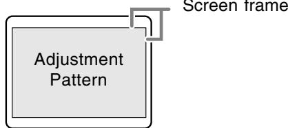
flowchart
graph TD
    A["Adjustment Pattern"] --> B["Screen frame"]
Adjusting the screen display
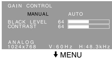
GAIN CONTROL Menu
When the monitor is used with a digital connection, this menu adjustment is not necessary.
AUTO
When [AUTO] is selected with the ▶ button, the [BLACK LEVEL] and [CONTRAST] settings are automatically adjusted. After the automatic adjustment, perform manual adjustment when necessary.
BLACK LEVEL
Total screen brightness can be adjusted while watching the color pattern. (◀▶ buttons)
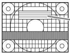
natural_image
Abstract geometric pattern with concentric circles and a diagonal bar, no text or symbols presentColor pattern
CONTRAST
While watching the color pattern, adjustments can be made so that all gradations appear.
(<► buttons)
Notes:
About AUTO (Auto Gain Control function)
- The Auto Gain Control adjusts contrast and black level based on the brightest and darkest colors of the image displayed.
- If you are not using the Adjustment Pattern it is necessary to have black area and white area of at least 5 mm x 5 mm on the screen. Adjustment may not be possible without those areas.
- If [OUT OF ADJUST] is displayed, perform manual adjustment.
WHITE BALANCE Menu
COOL ... Color tone bluer than standard
• ...... Color tone slightly bluer than standard
STD ..... Color tone standard setting
• ...... Color tone slightly redder than standard
WARM .. Color tone redder than standard USER
- Selecting [USER] will display the setting values for [R-CONTRAST], [G-CONTRAST] and [B-CONTRAST], in order to make fine adjustments.
- Use the ▼ button to select [R-CONTRAST], [G-CONTRAST] and [B-CONTRAST].
R-CONTRAST .....◀ button for blue-green
▶ button for red
G-CONTRAST .....◀ button for purple
▶ button for green
B-CONTRAST ..... ◀ button for yellow
▶ button for blue
Note:
- On settings other than [STD] not all gradations can be displayed. To display all gradations, set to [STD].
Adjusting the screen display
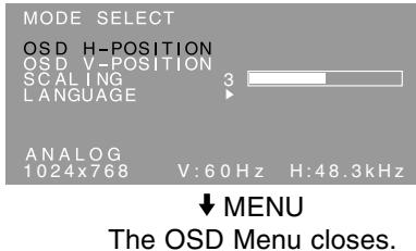
MODE SELECT Menu
Note:
- Depending on the resolution of the input signal, even if menu options can be selected, the display may not change.
OSD H-POSITION (OSD horizontal position)
The position of the OSD Menu can be moved to the left and right. (◀▶ buttons)
OSD V-POSITION (OSD vertical position)
The position of the OSD Menu can be moved up and down. (◀▶ buttons)
SCALING (Level of scaling)
The sharpness of the image can be adjusted.
(<► buttons)
Note:
- When an image area with a resolution smaller than 1024 x 768 pixels is selected, it is enlarged to cover the whole screen (i.e. the side ratio of the display may change).
LANGUAGE
You can choose the language used in OSD Menu.
- Press the ▶ button.
The Language Selection Menu will be displayed on the screen. - Use the ▼ button to choose a language.
- Press the MENU button.
This product is a 3D-ready LCD monitor which allows users to see stereoscopic images and videos without using special glasses. You can switch between 3D mode for stereoscopic (3D) display and 2D mode for conventional (2D) display.
Basic principle
In 3D mode, the parallax barrier divides light so that the right and left eyes of a viewer receive different lights. Consequently, the viewer can see stereoscopic images and videos.
In 2D mode, the parallax barrier does not divide light. Since the right and left eyes of a viewer receive the same light, the viewer sees conventional flat images.
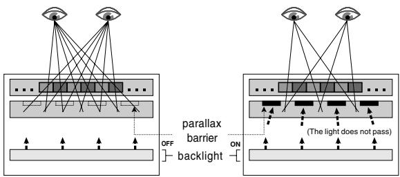
flowchart
graph TD
    A["Eye"] --> B["Parallax Barrier"]
    B --> C["Backlight"]
    C --> D["OFF"]
    D --> E["Light"]
    F["Light"] --> G["(The light does not pass)"]
    G --> H["ON"]
    H --> I["Light"]
    style A fill:#f9f,stroke:#333
    style F fill:#f9f,stroke:#333
    style I fill:#f9f,stroke:#333
Requirements for displaying 3D images
Applicable software for displaying 3D images
- Software which supports SHARP 3D Technology
- Other software which supports 3D display
Operating environment for 3D display
- The operation of the software supporting SHARP 3D Technology is guaranteed only on Windows XP (English version).
Operation in other language versions or other operating systems is not guaranteed.
- A digital connection is recommended for connecting to a computer.
- The required operating environment may vary depending on the software. Be sure to confirm the operating environment of your software.
Notes:
- SHARP 3D Technology was originally developed by SHARP to provide a 3D display on a computer screen.
- If your eyesight greatly differs between the right and left eye, or if you watch the screen mainly with a single eye, you may not see stereoscopic images. Images may or may not be able to see stereoscopically depending on the displayed contents.
- 3D effect varies depending on the person.
How to install SHARP Stereo Display
Supported OS: Windows XP (English version) Operation in other language versions is not guaranteed.
To display 3D images with this monitor using the software supporting SHARP 3D Technology, you must install the following software on your computer and connect the computer to the monitor with a USB cable.
- Sharp Stereo Display Driver (Driver to control the monitor's display mode through the USB port)
- Sharp Stereo Display Manager (Software to manage the monitor's display mode according to application status)
- Sharp Stereo Display Component (Software to display 3D images properly with this monitor)
Start installation with the USB cable disconnected. For software installation and USB connection procedures, refer to [ReadmeE.txt] in the [3D], [SSD], [English] folder in the supplied CD-ROM.
Notes:
- Be sure to follow the installation and connection procedures described in [ReadmeE.txt]. Otherwise, the installation may fail.
Supplied software
Install the following software from the supplied CD-ROM as necessary after installing the SHARP Stereo Display.
Note:
- If you want to install the following software, install the SHARP Stereo Display first.
SHARP Smart Stereo Photo Editor
Supported OS: Windows XP (English version) Operation in other language versions is not guaranteed.
This software supports SHARP 3D Technology. It converts images, taken with a digital camera, etc., using a stereo lens adapter, into a format which can be displayed in 3D with this monitor. Available style is Side-by-Side and Left/Right Independent.
Side-by-Side
| Left image | Right image |
Left/Right independent
| Left image | Right image |
(File1)
(File2)
How to install
If Microsoft.NET. Framework is not installed in your computer, install it before installing this software. In the CD-ROM, double click on [dotnetfx.exe] in the [3D], [3DSOFT], [dotnet], [English] folder, and follow the instructions displayed on the screen to complete the procedure.
- Load the supplied CD-ROM into the CD-ROM drive of the computer.
- Double click on [PhotoEditor.exe] in the [3D], [3DSOFT], [SLE], [English] folder.
- Follow the instructions displayed on the screen to complete the procedure.
How to use
Refer to [SHARP SmartStereo Photo Editor User Guide] or [SHARP SmartStereo Slide Show User Manual], by clicking on the [Start] button, and choosing [SHARP SmartStereo Photo Editor] from [All Programs].
SHARP Smart Stereo Camera Calculator
Supported OS: Windows XP (English version) Operation in other language versions is not guaranteed.
This software calculates attribute values to display an image taken with a stereo camera on the screen of this monitor.
How to install
- Load the supplied CD-ROM into the CD-ROM drive of the computer.
- Double click on [CamCalc.exe] in the [3D], [3DSOFT], [SLE], [English] folder.
- Follow the instructions displayed on the screen to complete the procedure.
How to use
Refer to [User Guide] by clicking on the [Start] button, and choosing [SHARP SmartStereo Calculator] from [All Programs].
Displaying 3D images
Notices on displaying 3D images
- Set the screen resolution to 1024 x 768. It is unable to display 3D image with other setting.
- Be sure to connect the USB cable while the monitor and computer are turned off. Then, turn on the monitor first and finally turn on the computer.
- Do not connect/disconnect the USB cable while the computer and/or monitor are turned on. Otherwise, a malfunction may result.
- Do not select 3D mode unless you display 3D images.
- If you select 2D mode while displaying a 3D image, the image may not display properly.
- For analog connection, adjust the screen properly using the automatic screen adjustment, etc.
- If the OSD Menu is hard to see in 3D mode, select 2D mode to make adjustments.
- Also refer to [ReadmeE.txt] in the [3D], [SSD], [English] folder in the supplied CD-ROM.
For software supporting SHARP 3D Technology
- The 3D display may be disabled when two or more users are logged on. In this case, let all users log off, and then log on as the user who logged on first.
Viewing position
To see images in 3D mode, there should be approximately 60 cm between you and the screen and you should be positioned in front of the screen. Straighten your back and direct both eyes so that you are looking straight at the screen.
Guideline for proper viewing position
In 3D mode, a red strip is displayed at the bottom of the screen. The best viewing position in 3D mode is the position where the entire red strip (or its bottom) appears darkest. Move your head slightly up/down, right/left, and forward/backward to adjust your position.
Note:
- With software that does not display a full screen, the red strip may not display at the bottom of the screen.
Switching display between 2D and 3D mode
For software supporting SHARP 3D Technology
When you display a 3D image with 3D display-ready software, the display mode is automatically switched to 3D mode and the power LED color changes to blue. When you display a 2D image, the display mode returns to 2D mode and the power LED color changes back to green.
If the display mode does not automatically switch to 3D mode, press the 3D button to switch the mode.
(When the 3D button is pressed again, the mode returns to 2D mode.)
Notes:
- When 3D mode is selected by pressing the 3D button, the mode may automatically return to 2D mode after the monitor resumes from power-saving mode.
- After the 3D mode is activated by pressing the 3D button, if the monitor is turned off once and turned on again, the mode returns to 2D mode.
For other software supporting 3D display
Confirm details by referring to the operation manual of the software.
Monitor care
Always remove the plug from the AC outlet when cleaning the monitor.
Cabinet and control panel section
Use a soft dry cloth to lightly wipe away any grime from the cabinet and control panel.
If they are very dirty, apply neutral detergent to a dampened soft cloth, wring it out well and wipe away grime.
LCD panel section
Use a soft dry cloth to lightly wipe away dirt and dust from the surface of the LCD panel. (A soft cloth such as gauze or that used for lens cleaning is suitable.)
CAUTION!
- Never use thinner, benzine, alcohol, glass cleaner, etc, as this could lead to color change or change in shape.
- Never scratch the monitor with anything hard or apply strong pressure as this could leave marks or result in malfunction.
Storage
If the monitor will not be used for a long period of time, be sure to remove the power plug from the AC outlet.
CAUTION!
- Do not leave the monitor in contact with rubber or plastic items for long periods of time as this could lead to color change or change in shape.
Troubleshooting
If you think the monitor may be faulty, please check the following points before taking it to be repaired. If afterwards it still does not work, please contact the shop where you purchased the monitor or your nearest SHARP authorized Service Center.
The monitor's fluorescent tubes have a limited life span.
- If the screen darkens, persistently flickers or does not light up, the fluorescent tube has reached the end of its operational life span.
Please inquire at the shop where you purchased the monitor or your nearest SHARP authorized Service Center. - In the initial period of use, due to the characteristics of fluorescent tubes the screen may flicker. (This is not a malfunction.) Should this happen, check by first turning off the power, then turning it on again.
No image appears on the screen (power LED is not lit).
- Are the AC adapter and power cord connected properly? (p.14)
No image appears on the screen (power LED is lit).
- Is the computer connected properly? (p.13)
- Is the computer turned on?
- Does the computer's signal timing correspond to monitor specifications? (p.28)
- Is the computer in power-saving mode?
Control buttons do not work.
- Is the adjustment lock on? (p.16)
The image appears distorted.
- Does the computer's signal timing correspond to monitor specifications? (p.28)
- If you are using the analog signal, perform automatic screen adjustment. (p.17)
- If you can change the refresh rate on the computer you are using, change the value to a lower frequency. (p.28)
No sound can be heard from the speakers.
- Is the audio cable connected correctly? (p.14)
- Perform the volume adjustment procedure. (p.16)
- Are the headphones connected?
- There is no sound from the speakers when the monitor is in power-saving mode (the power LED lights up orange).
Monitor care
The 3D image on the display appears blurred and doubled.
- Confirm if the 3D display compatible software is running.
- For software supporting SHARP 3D Technology
- Press the 3D button to enter 3D mode (the power LED changes to blue).
- Confirm that screen resolution is set to 1024 x 768.
- When two or more users are logged on, let all users log off, and then log on as the user who logged on first.
- The best viewing position in 3D mode is the position where the entire red strip (or its bottom) appears darkest. Move your head slightly up/down, right/left, and forward/backward to adjust your position.
When it is in 3D mode, the screen appears a little darker.
- In 3D mode, the screen appears a little darker than in 2D mode. (This is not a malfunction.)
The mode cannot be switched to 3D mode by pressing the 3D button.
- Does the current software support SHARP 3D Technology? If you are using software that does not support SHARP 3D Technology, refer to the operation manual of the software.
Specifications
Product specifications
Model name
LL-151-3D
LCD display
38 cm measured diagonally TFT 3D LCD module
Resolution (max.)
XGA 1024 x 768 pixels
(In 2D mode only. In 3D mode, the actual resolution is half because the horizontal pixels are divided between right and left eyes.)
Displayable colors (max.)
Approx.16.19 million colors (6 bit + FRC)
Brightness (max.)
2D mode: 370 cd/m²
3D mode: 140 cd/m²
(The screen brightness deteriorates over time.
Constant brightness cannot be maintained.)
Dot pitch
0.297 (H) x 0.297 (V) mm
Contrast ratio
500:1
Angle of visibility (2D mode)
Left-right 130°; up-down 115°
(contrast ratio > 10)
Screen display size
Horizontal 304.1 mm x Vertical 228.1 mm
Video signal
Analog: Analog RGB (0.7 Vp-p) [75Ω]
Digital: DVI standard based on 1.0
Sync signal
Separate Sync (TTL level: +/-)
Expansion compensation
Digital scaling (Enlarges VGA/SVGA etc. to full screen size.)
Plug & Play
VESA DDC2B compatible
Power management
VESA: based on DPMS
DVI: based on DMPM
Speaker output
1 W + 1 W
Input signal terminal
Digital/Analog: DVI-I 29 pin
PC connection terminal for 2D/3D selection
USB
Audio input terminal
Mini stereo jack
Headphone terminal
Mini stereo jack
Height adjustment
Adjustment range: approx. 60 mm
Screen tilt
Upward approx. 0-30°; downward approx. 0-5°
Screen swivel
Approx. 45° from the center to the left and
approx. 45^ from the center to the right.
Power supply
100-240 VAC, 50/60 Hz (Uses special AC adapter, type NL-A56J of Sharp Corporation)
Temperature of operating environment 5-35°C
Power consumption
25 W (with no audio input)
(29 W maximum, 2 W when in power-saving mode) (Uses special AC adapter)
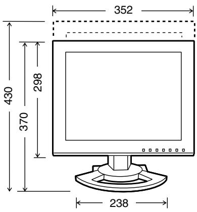
Dimensions
Approx. 352 (W) x 185 (D) x 370-430 (H) mm
Weight
Approx. 5.3 kg (approx. 3.4 kg excluding stand) (excluding signal cable and AC adapter)
Specifications
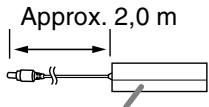
Dimensions (Units: mm)
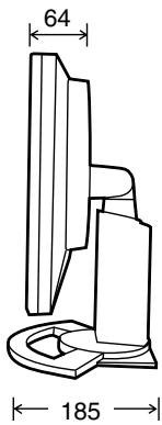
- Digital signal cable: approx. 2.0 m
- Analog signal cable: approx. 2.0 m
- Audio cable: approx. 2.0 m
- USB cable: approx. 2.0 m
- Special AC adapter:
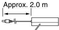
Approx. 125 (W) x 60 (D) x 33 (H) mm
Note:
- As a part of our policy of continuous improvement, SHARP reserves the right to make design and specification changes for product improvement without prior notice. The performance specification figures indicated are nominal values of production units. There may be some deviations from these values in individual units.
Specifications
Relevant signal timings (digital)
| Screen resolution | Hsync | Vsync | Dot frequency | |
| VESA | 640x480 | 31.5kHz | 60Hz | 25.175MHz |
| 37.9kHz | 72Hz | 31.5MHz | ||
| 37.5kHz | 75Hz | 31.5MHz | ||
| 800x600 | 37.9kHz | 60Hz | 40.0MHz | |
| 48.1kHz | 72Hz | 50.0MHz | ||
| 46.9kHz | 75Hz | 49.5MHz | ||
| 1024x768 | 48.4kHz | 60Hz | 65.0MHz | |
| 56.5kHz | 70Hz | 75.0MHz | ||
| 60.0kHz | 75Hz | 78.75MHz | ||
| US text | 720x400 | 31.5kHz | 70Hz | 28.3MHz |
- Recommended resolution is 1024 x 768.
- All are compliant only with non-interlaced.
- A computer with an output terminal conforming to DVI (DVI-D 24 pin or DVI-I 29 pin) and with XGA output capability can be connected here. (Depending on the type of computer to be connected, the display may not work correctly.)
- If the monitor is receiving timing signals that are not compatible, [OUT OF TIMING] will appear. Follow your computer's instruction manual to set the timing so that it is compatible with the monitor.
- If the monitor is not receiving any signal (synch signal), [NO SIGNAL] will appear.
Relevant signal timings (analog)
| Screen resolution | Hsync | Vsync | Dot frequency | |
| VESA | 640x480 | 31.5kHz | 60Hz | 25.175MHz |
| 37.9kHz | 72Hz | 31.5MHz | ||
| 37.5kHz | 75Hz | 31.5MHz | ||
| 800x600 | 35.1kHz | 56Hz | 36.0MHz | |
| 37.9kHz | 60Hz | 40.0MHz | ||
| 48.1kHz | 72Hz | 50.0MHz | ||
| 46.9kHz | 75Hz | 49.5MHz | ||
| 1024x768 | 48.4kHz | 60Hz | 65.0MHz | |
| 56.5kHz | 70Hz | 75.0MHz | ||
| 60.0kHz | 75Hz | 78.75MHz | ||
| US text | 720x400 | 31.5kHz | 70Hz | 28.3MHz |
| Power Macintosh series | 640x480 | 35.0kHz | 66.7Hz | 30.2MHz |
| 832x624 | 49.7kHz | 74.6Hz | 57.3MHz | |
| 1024x768 | 60.2kHz | 75Hz | 80.0MHz | |
- Recommended resolution is 1024 x 768.
- All are compliant only with non-interlaced.
- Frequencies for Power Macintosh are reference values. To connect, another adapter (commercially available) may be required.
- If the monitor is receiving timing signals that are not compatible, [OUT OF TIMING] will appear. Follow your computer's instruction manual to set the timing so that it is compatible with the monitor.
- If the monitor is not receiving any signal (synch signal), [NO SIGNAL] will appear.
Specifications
The DVI-I input connector pin
(DVI-I connector with 29 pins)
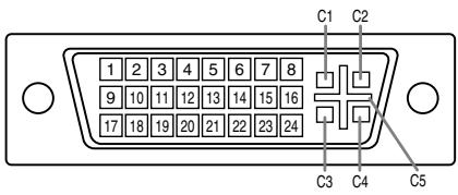
| No. | Function | No. | Function |
| 1 | TMDS data 2- | 16 | Hot plug detection |
| 2 | TMDS data 2+ | 17 | TMDS data 0- |
| 3 | TMDS data 2/4 shield | 18 | TMDS data 0+ |
| 4 | N.C. | 19 | TMDS data 0/5 shield |
| 5 | N.C. | 20 | N.C. |
| 6 | DDC clock | 21 | N.C. |
| 7 | DDC data | 22 | TMDS clock shield |
| 8 | Analog vertically synchronized signal | 23 | TMDS clock + |
| 9 | TMDS data 1- | 24 | TMDS clock - |
| 10 | TMDS data 1+ | C1 | Analog red image signal |
| 11 | TMDS data 1/3 shield | C2 | Analog green image signal |
| 12 | N.C. | C3 | Analog blue image signal |
| 13 | N.C. | C4 | Analog horizontally synchronized signal |
| 14 | +5V | C5 | Analog GND |
| 15 | GND |
Power management
The monitor is based on the VESA DPMS and the DVI DMPM standards. To activate the power management function, the video card and the computer used with it must also conform to these standards.
DPMS: Display Power Management Signalling
| DPMS mode | Screen | Power consumption | H-sync | V-sync |
| ON | Display on | 29 W | Yes | Yes |
| STANDBY | Display off | 2 W | No | Yes |
| SUSPEND | Yes | No | ||
| OFF | No | No |
DMPM: Digital Monitor Power Management
| DMPM mode | Screen | Power consumption |
| ON | Display on | 29 W |
| OFF | Display off | 2 W |
DDC (Plug & Play)
This monitor supports the VESA DDC (Display Data Channel) standard.
DDC is a signal standard for carrying out Plug & Play functions on the monitor or computer. It transfers information such as degree of resolution between the monitor and computer. You can use this function if your computer is DDC compliant and if it is set so that it can detect the Plug & Play monitor.
There are many varieties of DDC due to the differences between systems. This monitor works with DDC2B.
Installing set-up information and the ICC profile (For Windows)
Depending on the type of computer or OS, you may need to install the monitor set-up information on your system. If so, follow the steps below to install the monitor set-up information. (Depending on the type of computer or OS, command names and methods may differ. Please follow the computer's own operation manual while reading this.)
About the ICC profile
An ICC (International Color Consortium) profile is a file that describes the color reproduction characteristics of the LCD monitor. Using an application compatible with an ICC profile, highly accurate color reproduction can be realized.
- Windows 98/2000/Me/XP all use the ICC profile.
- When installing Windows 98/2000/Me/XP set-up information (described below), the ICC profile is also installed. If you would like to install the ICC profile only, please refer to Installing the ICC profile on page 32.
- When using the ICC profile, set the [WHITE BALANCE] to [STD].
For Windows 95
Installing monitor set-up information into Windows 95.
This explanation assumes that the CD-ROM drive is "D" drive.
- Load the supplied CD-ROM into the CD-ROM drive of the computer.
- Click on the [Start] button. From [Settings], choose [Control Panel].
- Double click on [Display].
- Click on [Settings], [Advanced Properties], and [Monitor], then [Change].
- Click on [Have disk], confirm that [Copy manufacturer's files from:] is [D:] then click [OK].
- Confirm that the monitor details are selected, and click [OK].
- Check that the monitor details are displayed, then click [Apply].
- Click [OK], and close the window.
- Eject the CD-ROM from the CD-ROM drive.
For Windows 98
Installing monitor set-up information into Windows 98, and setting the monitor's ICC profile as a predetermined value.
This explanation assumes that the CD-ROM drive is "D" drive.
If the "Add New Hardware Wizard" has appeared:
1. Load the supplied CD-ROM into the CD-ROM drive of the computer.
2. Click [Next].
3. Check [Display a list of all the drivers in a specific location, so you can select the driver you want.], then click [Next].
4. When [Models] is displayed, click on [Have disk], confirm that [Copy manufacturer's files from:] is [D:], and click [OK].
5. Confirm that the monitor details are selected, then click [Next], [Next], and [Finish]. If the "Add New Hardware Wizard" appears, repeat the installation commands beginning from 2 above.
6. Eject the CD-ROM from the CD-ROM drive.
If the "Add New Hardware Wizard" has not appeared:
- Load the supplied CD-ROM into the CD-ROM drive of the computer.
- Click on the [Start] button. From [Settings], choose [Control Panel].
- Double click on [Display].
-
Click on [Settings], [Advanced] and [Monitor].
-
In [Options], check [Automatically detect Plug & Play monitors] and click on [Change].
-
Click [Next].
-
Click on [Display a list of all the drivers in a specific location, so you can select the driver you want.], then click [Next].
-
When [Models] is displayed, click on [Have disk], confirm that [Copy manufacturer's files from:] is [D:], and click [OK].
-
Confirm that the monitor details are selected, then click [Next], [Next], and [Finish].
-
Check that the monitor details are displayed, then click [Apply].
-
Click [OK], and close the window.
-
Eject the CD-ROM from the CD-ROM drive.
Installing set-up information and the ICC profile (For Windows)
For Windows 2000
Installing monitor set-up information into Windows 2000, and setting the monitor's ICC profile as a predetermined value.
This explanation assumes that the CD-ROM drive is "D" drive.
- Load the supplied CD-ROM into the CD-ROM drive of the computer.
- Click on the [Start] button. From [Settings], choose [Control Panel].
- Double click on [Display].
- Click on [Settings], [Advanced] and [Monitor].
- Click on [Properties], [Driver] and [Update Driver].
- When [Upgrade Device Driver Wizard] appears, click [Next].
- Check [Display a list of the known drivers for this device so that I can choose a specific driver] and click [Next].
- When [Models] is displayed, click on [Have disk], confirm that [Copy manufacturer's files from:] is [D:], and click [OK].
- Select the monitor from the list displayed and click [Next].
- Click [Next], confirm that the monitor's name appears on the screen, and click [Finish]. If [The Digital Signature Not Found] appears, click [Yes].
- Click on [Close].
- Click [OK], and close the window.
- Eject the CD-ROM from the CD-ROM drive.
For Windows Me
Installing monitor set-up information into Windows Me, and setting the monitor's ICC profile as a predetermined value.
This explanation assumes that the CD-ROM drive is "D" drive.
If the "Add New Hardware Wizard" has appeared:
1. Load the supplied CD-ROM into the CD-ROM drive of the computer.
2. Check [Specify the location of the driver [Advanced]] and click [Next].
3. Check [Display a list of all the drivers in a specific location, so you can select the driver you want.], then click [Next].
4. When [Models] is displayed, click on [Have disk], confirm that [Copy manufacturer's files from:] is [D:], and click [OK].
5. Select the monitor details from the list, then click [Next], [Next], and [Finish]. If the "Add New Hardware Wizard" appears, repeat the installation commands beginning from 2 above.
6. Eject the CD-ROM from the CD-ROM drive.
If the "Add New Hardware Wizard" has not appeared:
- Load the supplied CD-ROM into the CD-ROM drive of the computer.
- Click on the [Start] button. From [Settings], choose [Control Panel].
- Double click on [Display].
- Click on [Settings], [Advanced] and [Monitor].
- In [Options], check [Automatically detect Plug & Play monitors] and click on [Change].
- Check [Specify the location of the driver [Advanced]] and click [Next].
- Check [Display a list of all the drivers in a specific location, so you can select the driver you want.] and click [Next].
- When [Models] is displayed, click on [Have disk], confirm that [Copy manufacturer's files from:] is [D:], and click [OK].
- Select the monitor details, then click [Next], [Next], and [Finish].
- Check that the monitor details are displayed, then click [Apply].
- Click [OK], and close the window.
- Eject the CD-ROM from the CD-ROM drive.
Installing set-up information and the ICC profile (For Windows)
For Windows XP
Installing monitor set-up information into Windows XP, and setting the monitor's ICC profile as a predetermined value.
This explanation assumes that the CD-ROM drive is "D" drive.
- Load the supplied CD-ROM into the CD-ROM drive of the computer.
- Click on the [Start] button. Choose [Control Panel].
- Switch to "Classic View".
- Double click on [Display].
- Click on [Settings], [Advanced] and [Monitor].
- Click on [Properties], [Driver] and [Update Driver].
- When [Hardware Update Wizard] appears, check [Install from a list or specific location [Advanced]] and click [Next].
- Check [Don't search. I will choose the driver to install.] and click [Next].
- Click on [Have Disk], confirm that [Copy manufacturer's files from:] is [D:], and click [OK].
- Select the monitor from the list displayed and click [Next]. If [has not passed Windows Logo testing...] appears, click [Continue Anyway].
- Confirm that the monitor's name appears on the screen.
- Click on [Finish].
- Click on [Close].
- Click [OK], and close the window.
- Eject the CD-ROM from the CD-ROM drive.
Installing the ICC profile
Installing the monitor's ICC profile. (If the set-up information has already been installed, so too has the profile, and there is no need to install it.)
This explanation assumes that the CD-ROM drive is "D" drive.
- Load the supplied CD-ROM into the CD-ROM drive of the computer.
- Click on the [Start] button. From [Settings], choose [Control Panel].
- Double click on [Display].
- Click on [Settings] and [Advanced].
- Click on [General] and from [Compatibility] select [Apply the new display setting without restarting], then click on [Color Management].
- Click [Add], and select CD-ROM as the file location.
- Choose the color profile that you would like to install, and click on [Add].
- Choose the profile and click on [Set As Default].
- Click [OK], and close the window.
- Eject the CD-ROM from the CD-ROM drive.
- When using the ICC profile, set the [WHITE BALANCE] to [STD].
Information about the ColorSync profile (For MacOS)
About the ColorSync profile
ColorSync is Apple Computer's color management system and enables color reproduction characteristics to be realized when used with a compatible application. A ColorSync profile describes the color characteristics of the LCD monitor.
Notes:
- This monitor's ColorSync profile works with MacOS 8.5 or above.
- When using the ColorSync profile, set the [WHITE BALANCE] to [STD].
Setting up the ColorSync profile
Notes:
- It is necessary to have PC Exchange or File Exchange installed in your system.
-
Depending on the type of computer or OS, command names and methods may differ. Please follow the computer's own operation manual while reading this.
-
Load the supplied CD-ROM into the CD-ROM drive of the computer.
- Copy the profile to be used from the CD-ROM to the ColorSync profile folder in the system folder.
- Using the ColorSync on the control panel, choose the profile to be used.
Instructions for attaching a VESA-compliant arm
An arm or stand based on the VESA standard (commercially available) can be attached to the monitor. Procurement of the arm or stand is at the customer's discretion.
Arms or stands able to be used
Attachments must satisfy the following.
- Compatible with the VESA standard.
- Have a gap of 75 mm x 75 mm between the screw holes on the section to be attached.
- Not be likely to fall off or break off after being attached to the monitor.
How to attach the arm or stand
- Be careful not to over bend the cable or add extension cords as this could lead to malfunction.
-
While following these instructions, please also refer to the installation instructions in the operation manual included with the arm or stand.
-
Remove the cables.
- Spread out a soft cloth on a suitable horizontal surface.
- Being careful not to damage the monitor, gently lay the monitor on it display-side down.
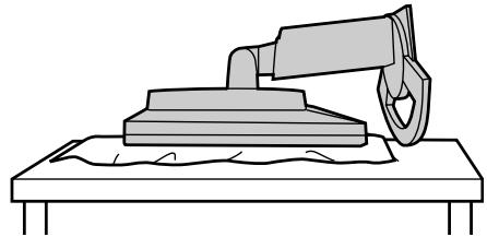
natural_image
Line drawing of a mechanical device pressing down on a workbench (no text or symbols)
CAUTION!
Securely grasp both the display and stand, and gently tip over. When the monitor is inclined, the stand may suddenly pop out and cause injury.
- Remove the four screws and then remove the stand from the monitor.
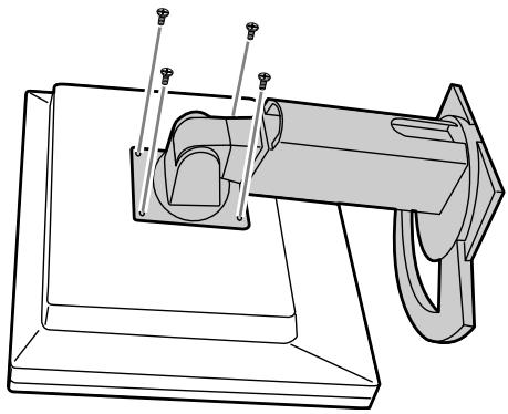
natural_image
Technical line drawing of a mechanical assembly with mounting base and cylindrical component (no text or symbols)Notes:
- The stand is specially made for use with this monitor. Once having removed the stand, never attempt to attach it to another device.
- Once having removed the screws, store them together with the stand and if the stand is ever re-attached be sure to use the original screws. Using different screws could lead to a malfunction.

CAUTION!
Do not disassemble the stand. Parts may spring out and cause injury.
- Attach the arm to the monitor with the four screws.
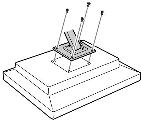
natural_image
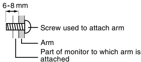
Technical line drawing of a mechanical assembly with three pins and a central base (no text or symbols)Note:
- The screws used to attach the arm should be M4 screws with a length of 6-8 mm protruding from the surface to be attached. Using different screws could cause the monitor to fall off or to be internally damaged.
Inhaltsverzeichnis
natural_image
Illustration of a hand using a computer monitor to press or install a device (no text or symbols visible)natural_image
Line drawing of a computer monitor with cables attached to its base (no text or symbols)natural_image
Line drawing of a computer monitor mounted on a stand with cables, no text or symbols presentnatural_image
Diagram of a cable connector inserted into a rectangular block, showing wiring and a plug (no text or symbols)Macintosh-Wandleradapter
natural_image
Abstract geometric pattern with concentric circles and horizontal stripes on a grid background (no text or symbols)natural_image
Abstract geometric pattern with concentric circles and a diagonal bar, no text or symbols presentFarbmuster
CONTRAST
DPMS: Display Power Management Signalling
DMPM: Digital Monitor Power Management
natural_image
Line drawing of a mechanical device pressing down on a workbench (no text or symbols)
ACHTUNG:
natural_image
Technical line drawing of a mechanical assembly with pins and a central component (no text or symbols)Hinweise:
natural_image
Technical line drawing of a mechanical assembly with three pins and a central base (no text or symbols)Hinweis:
natural_image
Illustration of a hand using a computer monitor to press or install a device (no text or symbols visible)natural_image
Line drawing of a computer monitor mounted on a stand with cables, no text or symbols presentnatural_image
Line drawing of a computer monitor mounted on a stand with cables, no text or symbols presentnatural_image
Diagram showing a connector inserted into a rectangular block with an arrow indicating insertion (no text or symbols present)natural_image
Abstract geometric pattern with concentric circles and a central semicircle on a grid background (no text or symbols)natural_image
Abstract geometric pattern with concentric circles and a diagonal stripe, no text or symbols presentMire de couleur
CONTRAST
| Image Gauche | Image Droite |
| Image Gauche | Image Droite |
Dimensions (L x P x H)
Approx. 352 mm x 185 mm x 370 - 430 mm
Poids
Approx. 125 mm (L) x 60 mm (P) x 33 mm (H)
Remarque :
DPMS: Display Power Management Signalling
natural_image
Simple line drawing of a mechanical device with a lever and base, resting on a flat surface (no text or symbols)
Attention :
natural_image
Technical line drawing of a mechanical assembly with mounting base and clamping device (no text or symbols)Remarques :
natural_image
Technical line drawing of a mechanical assembly with three pins and a central base (no text or symbols)Remarque :
natural_image
Illustration of a hand using a computer monitor to press or install a device, with no visible text or symbols.natural_image
Line drawing of a computer monitor with cables attached to its base (no text or symbols)natural_image
Line drawing of a computer monitor mounted on a stand with cables, no text or symbols presentnatural_image
Diagram showing a cable inserted into a rectangular block with a connector inserted (no text or symbols present)natural_image
Abstract geometric pattern with concentric circles and a horizontal bar, no text or symbols presentMenu ADJUSTMENT (REGOL)
natural_image
Abstract geometric pattern with concentric circles and a diagonal bar, no text or symbols presentTracciato di colore
CONTRAST (CONTRASTO)
DPMS: Display Power Management Signalling
DMPM: Digital Monitor Power Management
natural_image
Line drawing of a mechanical device pressing down on a workbench (no text or symbols)
ATTENZIONE:
natural_image
Technical line drawing of a mechanical assembly with mounting base and clamping device (no text or symbols)Note:
natural_image
Technical line drawing of a mechanical assembly with three pins and a central base (no text or symbols)Nota:
(On Screen Display).
Ajuste de altura
natural_image
Illustration of a hand using a computer to switch a device, no text or symbols presentnatural_image
Line drawing of a computer monitor mounted on a stand with cables, no text or symbols presentnatural_image
Line drawing of a computer monitor mounted on a stand with cables, no text or symbols presentnatural_image
Diagram showing a cable inserted into a rectangular box with a connector inserted (no text or symbols present)natural_image
Abstract geometric pattern with concentric circles and a horizontal bar, no text or symbols presentnatural_image
Abstract geometric pattern with grid, curved shapes, and a diagonal line (no text or symbols)Patrón cromático
CONTRAST
natural_image
Line drawing of a robotic arm gripping a mechanical component on a workbench (no text or symbols)
Precaución:
natural_image
Technical line drawing of a mechanical assembly with pins and a curved component (no text or symbols)Notas:
natural_image
Technical line drawing of a mechanical assembly with three pins and a central base (no text or symbols)Nota:
- IMPORTANT:
- FCC Statement
- Declaration of Conformity
- SHARP LCD Color Monitor LL-151-3D
- Notice for Users in Europe
- Notice for Users in Australia
- Service Inquiries
- Table of Contents
- Tips and safety precautions
- Location
- The Power Cord
- Use of AC adapter
- Monitor and accessory checklist
- Notes:
- Manual Scope
- Angle adjustment, height adjustment
- CAUTION!
- Angle adjustment
- Height adjustment
- Connecting the monitor and turning the monitor on and off
- Cable storage
- Connecting the monitor to a computer
- Digital connection
- Analog connection
- Connect the supplied audio cable
- Connection of headphones (commercially available)
- Connecting the monitor to a power source
- Turning the power on
- Turning the power off
- Adjusting the screen display and speaker volume
- For digital signal
- For analog signal
- Note:
- Resetting all adjustment values
- ADJUSTMENT Menu reset
- Adjustment lock function
- Adjustment lock release
- Adjusting the backlight
- Adjusting the speaker volume
- Automatic screen adjustment (When using an analog signal)
- Screen display for adjustment
- Opening the Adjustment Pattern (for Windows)
- Adjusting the screen automatically
- Adjusting the screen display
- Manual screen adjustment
- ADJUSTMENT Menu
- AUTO
- CLOCK
- PHASE
- H-POS (horizontal positioning) and V-POS (vertical positioning)
- GAIN CONTROL Menu
- BLACK LEVEL
- CONTRAST
- About AUTO (Auto Gain Control function)
- WHITE BALANCE Menu
- MODE SELECT Menu
- OSD H-POSITION (OSD horizontal position)
- OSD V-POSITION (OSD vertical position)
- SCALING (Level of scaling)
- LANGUAGE
- Basic principle
- Requirements for displaying 3D images
- Applicable software for displaying 3D images
- Operating environment for 3D display
- How to install SHARP Stereo Display
- Supplied software
- SHARP Smart Stereo Photo Editor
- How to install
- How to use
- SHARP Smart Stereo Camera Calculator
- Displaying 3D images
- Notices on displaying 3D images
- For software supporting SHARP 3D Technology
- Viewing position
- Guideline for proper viewing position
- Switching display between 2D and 3D mode
- For other software supporting 3D display
- Monitor care
- Cabinet and control panel section
- LCD panel section
- Storage
- Troubleshooting
- The image appears distorted.
- No sound can be heard from the speakers.
- The 3D image on the display appears blurred and doubled.
- When it is in 3D mode, the screen appears a little darker.
- The mode cannot be switched to 3D mode by pressing the 3D button.
- Specifications
- Product specifications
- The DVI-I input connector pin
- Power management
- DDC (Plug & Play)
- Installing set-up information and the ICC profile (For Windows)
- About the ICC profile
- For Windows 95
- For Windows 98
- For Windows 2000
- For Windows Me
- For Windows XP
- Installing the ICC profile
- Information about the ColorSync profile (For MacOS)
- About the ColorSync profile
- Setting up the ColorSync profile
- Instructions for attaching a VESA-compliant arm
- Arms or stands able to be used
- How to attach the arm or stand
- Inhaltsverzeichnis
- ACHTUNG:
- Hinweise:
- Hinweis:
- Remarque :
- Attention :
- Remarques :
- Menu ADJUSTMENT (REGOL)
- CONTRAST (CONTRASTO)
- ATTENZIONE:
- Nota:
- Ajuste de altura
- Precaución:
- Notas:
Brand : SHARP
Model : LL-151-3D
Category : Calculator