Superbe Comfort - Electric bike Raleigh - Free user manual and instructions
Find the device manual for free Superbe Comfort Raleigh in PDF.


| Brand | Raleigh |
| Model | Superbe Comfort |
| Product type | Electric bike with pedal assistance |
| Drive unit | Bosch Drive Unit 45 (ref. 0 275 007 003) |
| Nominal power | 350 W |
| Maximum torque | 50 Nm |
| System nominal voltage | 36 V |
| Battery | Lithium-ion Bosch, 36 V, 8 Ah, 288 Wh (ref. 1 270 020 500-507) |
| Battery weight | 2.5 kg |
| Drive unit weight | 4 kg |
| Control computer weight | 0.15 kg |
| Charger weight | 0.8 kg |
| Control computer | Bosch HMI (ref. 1 270 020 900) |
| Assistance modes | ECO, TOUR, SPORT, SPEED (3 levels each + off) |
| Maximum assisted speed | 45 km/h |
| Maximum range | Up to 105 km (depending on conditions) |
| Front light | 2.7 W (6 V) |
| Rear light | 0.3 W (6 V) |
| Charger | Bosch, 115/230 V, 50/60 Hz, 4 A (normal) / 1 A (silent) |
| Charging time (8 Ah) | Approx. 2.5 h (normal mode) / 8 h (silent mode) |
| Protection (IP rating) | IP54 (dust and splash water protected) |
| Operating temperature | -5 °C to +40 °C |
| Storage temperature | -10 °C to +50 °C (battery: -10 °C to +60 °C) |
| Permissible charging temperature range | 0 °C to +40 °C |
| Maintenance | Clean with a damp cloth; do not immerse or use a high-pressure cleaner |
| Repairs | Entrust to an authorized bicycle dealer; use only genuine Bosch spare parts |
Frequently Asked Questions - Superbe Comfort Raleigh
User questions about Superbe Comfort Raleigh
0 question about this device. Answer the ones you know or ask your own.
Ask a new question about this device
Download the instructions for your Electric bike in PDF format for free! Find your manual Superbe Comfort - Raleigh and take your electronic device back in hand. On this page are published all the documents necessary for the use of your device. Superbe Comfort by Raleigh.
USER MANUAL Superbe Comfort Raleigh
natural_image
Modern white bicycle with black frame and visible exhaust plume, no text or symbols on the body
natural_image
Side view of a modern light green bicycle with black frame and front wheel (no text or symbols visible)Bruksanvisning
Svenska
I Allmän bruksanvisning
II Bruksanvisning | Snabb Pedelec
III Bruksanvisning | Pedelec med mittmotor
IV User Manual | Pedelec with front motor (English version)
V User Manual | Pedelec Impulse (English version)
VI User Manual | Pedelec Groove (English version)
VII User Manual | BionX (English version)
VIII Bruksanvisning | Bosch

natural_image
Side view of a modern light green bicycle with black frame and front seat (no text or symbols visible)
natural_image
Side view of a modern bicycle with blue frame and black front wheel (no visible text or symbols)I
natural_image
White and black bicycle with a white frame and 'PALEIGH' branding, shown against a plain white background (no text or symbols on the bike body)natural_image
Side-by-side illustrations of a person wearing a helmet, showing correct and incorrect posture (no text or symbols)natural_image
Side view of a modern bicycle with front wheel and rear suspension (no visible text or symbols)natural_image
Black bicycle with a simple design and front livery, shown in isolated posture (no text or symbols visible)natural_image
Side view of a modern bicycle with black frame and white wheels (no text or symbols visible)natural_image
Side view of a black bicycle with red accents and white frame (no visible text or symbols)natural_image
Close-up of a black mechanical component with threaded end (no visible text or symbols)natural_image
Close-up of a black mechanical component with threaded end (no visible text or symbols)natural_image
Six mechanical components with exploded views, numbered 1 to 3, showing internal structures without any text or symbols.1 Systempedaler MTB
2 Touring- eller sportpedaler
3 Systempedaler racingcykel
natural_image
Mechanical clamp or lever component with labeled parts (1, 2), no visible text or symbols on the main body.natural_image
Close-up of a black mechanical lever handle with 'OPEN' label and directional arrow (no readable text or symbols)natural_image
Close-up of a black mechanical clamp or bracket with a white arrow indicating rotation (no text or symbols visible)
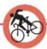
natural_image
Silhouette of a person riding a bicycle, no text or symbols present
natural_image
Silhouette of a person riding a bicycle with a red downward arrow indicating motion (no text or symbols)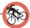
natural_image
Close-up of a hand adjusting a car suspension system with visible springs and tubing (no text or symbols)natural_image
Close-up of a bicycle's seat structure with visible tracks and legs (no text or symbols)Tvåskruvsstöd
natural_image
Close-up of a black bicycle saddle resting on a metal stand (no text or symbols visible)Klämfäste
natural_image
Close-up of a robotic arm with black and white bands, no visible text or symbolsFjädrad sadelstolpe
natural_image
Close-up of a hand using a tool to adjust or install a mechanical component (no visible text or symbols)natural_image
Close-up of a mechanical component with directional arrows indicating motion (no text or symbols)natural_image
Close-up of a bicycle steering wheel with attached brake calipers and a 'COTRANT' brand logo (no text or symbols on the diagram itself)natural_image
Close-up of a robotic arm with red dashed lines indicating motion or force, no visible text or symbolsnatural_image
Close-up of hands using a tool to adjust or install a mechanical component (no visible text or symbols)natural_image
Close-up of a black and white FSB brand headbell with visible branding (no text or symbols on body)Styrsats
natural_image
Black mechanical fork with engraved markings (no visible text or symbols)
natural_image
Close-up of a black bicycle front post with visible brackets and mounting feet (no text or symbols)Kolfibergaffel Fjädergaffel
natural_image
Technical line drawing of a mechanical frame assembly (no text or symbols)Helfjädrad ram
natural_image
Close-up of a hand using a screwdriver to adjust the wheel rim (no text or symbols visible)natural_image
Mechanical assembly diagram showing a chain and gear mechanism (no text or labels)Kassettknut
natural_image
Technical line drawing of a mechanical assembly with no visible text or symbols
Guide OK
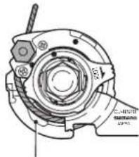
natural_image
Technical line drawing of a mechanical assembly with no visible text or symbols
Guide inte OK
19 Cykelväxlar
19.1 Kedjeväxel
natural_image
Mechanical assembly diagram showing a lever mechanism with a downward arrow indicating motion (no text or symbols present)
natural_image
Two black bicycle tire clips with metallic caps, shown against a white background (no text or symbols visible)Nytt bromsbelägg
natural_image
Close-up of a black mechanical component with a metallic shaft and flange (no visible text or symbols)Slitet bromsbelägg

natural_image
Mechanical components including a pair of pliers and a circular brake disc (no text or symbols visible)Skivbroms

natural_image
Close-up of a black industrial valve component with a handle attachment (no visible text or symbols)Däckdynamo
natural_image
Exterior view of a modern electric bus with visible brand name 'Nexus' and internal components (no additional signage or text)Navdynamo
natural_image
Close-up of a bicycle wheel rim with visible spokes and a central hub (no text or symbols)natural_image
Close-up of a bicycle's front wheel and rear truss (no text or symbols visible)natural_image
Close-up of bicycle wheel and suspension components (no visible text or symbols)
natural_image
Close-up of a bicycle's wheel and suspension mechanism (no text or symbols visible)natural_image
Side profile illustration of a person wearing a helmet with a pull bar (no text or symbols)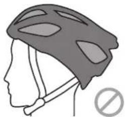
natural_image
Side profile of a person wearing a helmet with a no-smoking symbol (no text or labels)
natural_image
Close-up of a bicycle brake lever with black grip and white caliper (no visible text or symbols)
Copyright © 2012 Raleigh Univega GmbH
natural_image
Black and white photo of a modern bicycle with red accents, showing front wheel, rear seats, and front wheel (no visible text or symbols)
natural_image
White electronic device with a cable and labeled pin (no visible text or symbols)Laddare

LCD-manöverelement

1 Batteri
2 Batterilås
3 Motorenhet
4 Manöverelement
5 Laddare
Bästa kund,
natural_image
White portable electronic device with a black logo on its side (no visible text or symbols)4.1 Manöverelementets funktion
4.1.1 Knapp på/av
natural_image
Close-up of a bicycle's front wheel and side panel, showing black and white components (no text or symbols visible)natural_image
White electronic device with a small internal component and a cable, no visible text or symbols.8Felavhjälpning20
natural_image
Close-up of a hand adjusting a white plastic device mounted on a silver vehicle (no visible text or symbols)Låsa upp batteriet
natural_image
Close-up of a bicycle seatbelt mechanism with hand adjusting the component (no visible text or symbols)natural_image
Close-up of a black motorcycle handle and grip with a circular button, no visible text or symbolsHastighetsbrytare
3 Laddabatteriet
natural_image
Close-up of a hand adjusting a white electronic device with a control panel (no visible text or symbols)Låsa upp batteriet

natural_image
Close-up of a bicycle seatbelt mechanism with a hand adjusting the component (no visible text or symbols)Copyright © 2012 Raleigh Univega GmbH
natural_image
Raleigh 100 bicycle with green accents and front wheel, shown from front and side (no text or symbols on the bike body)
natural_image
White electronic device with a cable and labeled pin (no visible text or symbols)Laddare
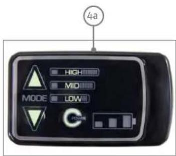
LED-manöverelement
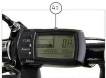
LCD-manöverelement

1 Batteri
2 Batterilås
3 Motorenhet
4 Manöverelement
4a LED
4b LCD
5 Laddare
Bästa kund,
natural_image
White portable electronic device with a black logo on its side (no visible text or symbols on the device body)
4.1 LED-manöverelement 12
4.1.1 Automatiskavstängning 13
4.2 LCD-manöverelement 13
natural_image
Close-up of a bicycle's front wheel and side panel, showing black and white components with no visible text or symbols.5.1 Stödets funktion 17
5.2 Räckvidd 18
natural_image
White plastic electronic device with a cable and a small display (no visible text or symbols)8.1.2.3 Indikation "E1" 25
8.1.2.4 Indikation "E9" 25
Dover 125th Impulse, Dover Premium Impulse, Dover XXL Impulse, Dover HS Impulse, Impulse XXL, Impulse, Impulse HS, Impulse Compact, Leeds Compact, Dover Impulse
natural_image
Close-up of a hand adjusting a car's battery compartment with a sensor (no visible text or symbols)Låsa upp batteriet
natural_image
Close-up of a bicycle seatbelt mechanism with a hand adjusting the component (no visible text or symbols)natural_image
Close-up of a black motorcycle handle with attached grip and control knob (no visible text or symbols)natural_image
Close-up of a hand adjusting a car's seatbelt switch (no visible text or symbols)Låsa upp batteriet

natural_image
Close-up of a bicycle's front wheel assembly with a hand adjusting the seat (no visible text or symbols)Copyright © 2012 Raleigh Univega GmbH
User Manual Pedelec with front motor
English
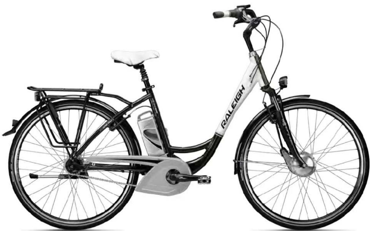
natural_image
Black and white exterior view of a Raleigh bicycle with visible front wheel, rear seat, and side panel (no text or symbols on the bike body)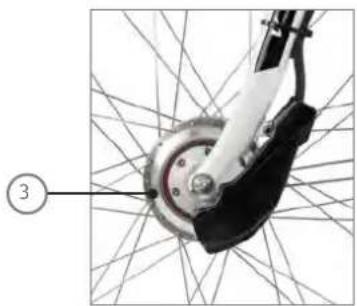
natural_image
Close-up of a bicycle wheel assembly with a numbered label pointing to the component (no text or symbols on the diagram itself)Motor
LED control panel

natural_image
White electronic device with a cable and labeled pin (no visible text or symbols)Charger

Dear Customer,
Thank you for choosing a Pedelec (pedal electric cycle) from us. This bike is equipped with an electric drive that assists you when you are cycling. This will make your trip much more enjoyable if you are riding up hills, carrying loads or riding into the wind. You can decide yourself how much you want to use it. The purpose of this User Manual is to help you get the most out of your Pedelec and use it correctly.
Structure of User Manual
If you want to get started right away, refer to the brief introduction in ➔ Chapter 1 "Quick start"
The individual steps are subsequently explained in detail, supplemented by illustrations and diagrams.
For more detailed information on your Pedelec, refer to Chapter 12 "Technical data".
The information in this User Manual specifically refers to your Pedelec only. For general information, on the bike technology that features in your Pedelec for example, refer to the General User Manual.

Even if you can't wait to go for your first ride, in the interest of your own safety you should read Chapter 1 "Quick start" carefully without fail before use.
In addition to texts and tables, the User Manual contains the following symbols that denote important information or dangers.

WARNING about possible physical injury, increased risk of falls or other injuries

IMPORTANT ADDITIONAL INFORMATION or special information on using the bike

NOTE about possible damage to property or the environment
Content
EC Declaration of Conformity
2012
2013
1 Quick start 7
2 Pedelec / fundamental legal principles 8
2.1 Meaning for the rider 8
2.2 Pushing assistance 8
3 Charging the battery 9

natural_image
White portable electronic device with a black logo on its side (no visible text or symbols)3.1 Charging operation
3.2 Fitting the battery
4 LED control panel (display)

4.1 Switching the light on and off
4.2 Automaticswitch-off
5
6
9
9
10
11
11
5 Assistance by the electric motor
12
natural_image
Close-up of a bicycle wheel and suspension mechanism with connecting lines (no text or symbols visible)5.1 Operating principle of assistance 12
5.2 Riding your Pedelec efficiently 13
6 Battery 14
6.1 Straightforwardcharging 14
6.2 High degree of safety due to battery management 14
6.3 Straightforwardstorage 14
6.4 Battery information system 15
6.4.1 Checking the battery charge state 15
6.4.2 Checking the battery capacity 15
6.5 Service life and warranty 16
6.5.1 the electric drive 16
6.5.2thebattery 16
7 Charger 17

natural_image
White electronic device with a small internal component and a visible label (no readable text or symbols)8 Troubleshooting 17
8.1 Problems/solutions: Flash patterns and their meaning 18
8.1.1 Additional possible sources of errors 18
9 Removing the front wheel 19
10 Cleaning 20
11 Warnings 21
12 Technical data 22
EC Declaration of Conformity 2012 CE
The manufacturer: Raleigh Univega GmbH
Siemensstraße 1–3
49661 Cloppenburg, Germany
Telephone: +49 (0) 4471/9234-0
hereby declares that the following products:
Product description: Raleigh Pedelec Panasonic
Model designation:
Dover de Luxe 7G, Dover de Luxe 8G, Dover 3G, Dover Premium 8G, Leeds Sport 11G, Leeds HS 8G, Leeds Roller, Leeds Tour 7G, Stoker Lite Premium, Stoker 360, Stoker Lite 8G, Stoker DD, Dover LTD, Dover XXL LTD
Product description: Raleigh Impulse
Model designation:
Dover 125th Impulse, Dover Premium Impulse, Dover XXL Impulse, Dover HS Impulse, Impulse XXL, Impulse, Impulse HS, Impulse Compact, Leeds Compact, Dover Impulse
Product description: Raleigh Groove
Model designation:
Groove F3, Groove F8
Product description: Raleigh BionX
Model designation:
Blackburn 7, Blackburn 5, Blackburn 3
Product description:
Raleigh Bosch Pedelec
Model designation:StokerB
Year of manufacture:
2012
comply with all of the relevant requirements of the Machinery Directive (2006/42/EC).
Furthermore, the machine complies with all of the requirements of the Electromagnetic Compatibility Directive (2004/108/EC).
The following harmonized standards have been applied:
DIN EN 15194 Cycles – Electrically power-assisted cycles – EPAC cycles
DIN EN 14764 City and trekking bikes – Safety requirements and test methods
Technical documentation filed at:
49661 Cloppenburg, Germany

Olaf Flunkert
Production, Purchasing and
Technology Manager
M. K. Chen Hoge
Karl-Heinz Lange
Design and Development Manager
49661 Cloppenburg, Germany
21.09.2011
EC Declaration of Conformity 2013 CE
The manufacturer: Raleigh Univega GmbH
Siemensstraße 1–3
49661 Cloppenburg, Germany
Telephone: +49 (0) 44 71 / 92 34 - 111
hereby declares that the following products:
Product description: Raleigh Pedelec Panasonic
Model designation: Dover de Luxe P8 36V, Dover de Luxe P8R 36V, Dover de Luxe P8 26V, Dover de Luxe 8G 26V, Dover de Luxe 7G 26V, Dover de Luxe 2x8 8G, Leeds Sport
Product description: Raleigh Impulse Pedelec
Model designation: Impulse iR, Impulse iR HS, Impulse iR Classic, Impulse iR Premium, Impulse iR XXL, Impulse iR Compact, Stocker i11 Di2, Stocker i Light Premium, Stocker iR Light, Stocker IDD, Leeds i Light, Leeds i HS, Leeds iR HS, Leeds i Roller, Leeds iR Tour, Leeds I Compact, Dundee iR Cargo, Dundee i Compact, Dover i, Dover I HS, Dover i XXL, Dover i Premium, Dover i360, Dover i360 Harmony
Product description: Raleigh Groove Pedelec
Model designation: GrooveF8
Product description: Raleigh Xion Pedelec
Model designation: Blackburn 5, Blackburn 3
Product description: Raleigh Bosch Pedelec
Model designation: Stoker B8, Stoker B9
Year of manufacture: 2013
comply with all of the relevant requirements of the Machinery Directive (2006/42/EC).
Furthermore, the machine complies with all of the requirements of the
Electromagnetic Compatibility Directive (2004/108/EC).
The following harmonized standards have been applied:
DIN EN 15194 Cycles – Electrically power-assisted cycles – EPAC cycles
DIN EN 14764 City and trekking bikes – Safety requirements and test methods
Technical documentation filed at:
49661 Cloppenburg, Germany

Olaf Flunkert
Production, Purchasing and
Technology Manager
Mard-Heni Hoge
Karl-Heinz Lange
Design and Development Manager
49661 Cloppenburg, Germany
14.05.2012
1 Quickstart
- Charge the battery completely before riding for the first time.
natural_image
Close-up of a hand adjusting a car's seatbelt with a small emblem (no visible text or symbols)Unlocking the battery
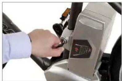
- To remove the battery, grip the handle, insert the key into the lock and turn it anticlockwise. The battery is now unlocked.
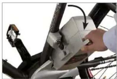
- Tilt the battery sideways and lift it with both hands out of the holder.
natural_image
Close-up of a bicycle's front wheel assembly with a hand adjusting the seat (no visible text or symbols)Tilt when removing
- Put the battery in the docking station of the charger. The battery LEDs light up or flash. You must fully charge the battery before using it for the first time.
- Once all LEDs have gone out, take the battery out of the docking station.
- Reinsert the battery into the holder on the Pedelec from the left-hand side. Move the battery outwards at an angle of roughly 45^ as you do so, as you did when you took it out of the holder. Move the battery into the upright position until the locking mechanism engages. If the key is still in the lock, you will need to turn it clockwise and pull it out to allow the battery to lock in place.
- Make sure that the battery is securely positioned and that the key is no longer in the lock.
- Push the "Power" button on the control panel on the handlebar. Wait for 2 seconds before turning the pedals. The drive system requires this time
when no force is applied to the pedals to adjust the power sensor correctly.
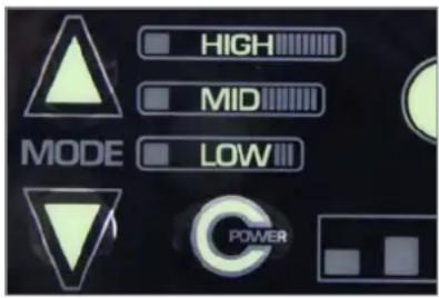
- The intermediate power-assist mode appears on the display panel of the LED control panel. Press the "Mode" buttons to select the amount of assistance: "gentle/LOW", "intermediate/MID" or "powerful/HIGH". Press this button once to change the assist level by one level. You can increase or reduce the assistance, depending on which "Mode" button you press.
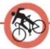
Always operate one of the brakes before putting one of your feet on a pedal as the motor pulls your bike away immediately. This starting assistance is very convenient, especially when starting on hills. If you start off in road traffic or on unsurfaced roads without controlling your speed, you could come off your bike and seriously injure yourself.
- You can now ride off.
2 Pedelec/fundamental legal principles
The fundamental idea behind the Pedelec is not only to be able to cover greater distances more quickly, but also do this comfortably. You can choose to relax and let the bike do the work, exert yourself more physically, or simply to get from A to B as fast as possible. You can decide this yourself by choosing an appropriate assist level.
This gives you more confidence on the road, as the powerful acceleration gives you more control and a greater degree of security. Your Pedelec assists you with up to 250 watts of power which takes you up to the speed of 25 km/h.
In some EU countries, the Pedelec, like all other bikes, must comply with certain regulations, the Road Traffic Licensing Regulations (StVZO) in Germany for example. Please observe the relevant explanations and general information provided in the General User Manual.
These statutory requirements apply for a Pedelec:
- The motor is designed only to provide pedalling assistance, i.e. it can only "assist" the rider when he/she turns the pedals.
- The average motor output must not exceed 250 W.
- As the speed increases, the rate at which the motor output reduces must also increase more intensely.
- The motor must switch off once the bike reaches a speed of 25 ~km / h .
2.1 Meaning for the rider
You do not legally have to wear a helmet. In the interest of your own safety, however, you should never ride without a helmet.
- You do not legally have to have a driving licence.
- You do not legally have to have insurance.
- No age restriction applies for a Pedelec.
- The regulations governing the use of cycle paths are the same as for normal bikes.
These regulations apply to you wherever you are in the European Union. It is possible that different regulations exist in other countries, also inside the EU in individual cases. Before using your Pedelec abroad, find out about the legal situation in the relevant country.
2.2 Pushingassistance
You can have your specialist cycle shop fit what is known as "pushing assistance" to your bike.

natural_image
Close-up of a black automotive plug with attached control switch and lever (no visible text or symbols)Button for pushing assistance
The pushing assistance moves the Pedelec slowly at a maximum speed of 6 km / h without you having to turn the pedals, e. g. if you are manoeuvring in a tight space or are pushing your Pedelec out of a basement garage.
In Germany, if you were born later than 01. 04. 1965, you must have a moped test certificate before you can fit the pushing assistance. If you already have another type of driving licence, this automatically includes the moped test certificate.
The pushing assistance is not suitable for use as starting assistance.
3 Charging the battery
To charge the battery, you have to take it out of the holder on the Pedelec.

Grip the battery by the handle, insert the key into the lock and turn it anticlockwise. The battery is now unlocked and can be removed from the Pedelec by tilting it sideways. In doing so, hold on tight to the battery to prevent it from being dropped.

natural_image
Close-up of a hand adjusting a car's battery panel with a sensor (no visible text or symbols)Unlocking the battery

natural_image
Close-up of a bicycle's front wheel assembly with a hand adjusting the seat (no visible text or symbols)Tilt to remove
You should now remove the key and keep it in a safe place to prevent it from breaking off or being lost.
3.1 Chargingoperation
Before charging the battery, read the information on the charger carefully.
- Take the charger provided out of its packaging and plug the mains plug into a socket (230 V, observe type plate on the charger).

Type plate on charger: Front and back
-
Put the battery in the docking station of the charger.
-
The charging operation starts. The battery LEDs light up or flash. Once all 5 LEDs have gone out, the battery is fully charged. You can leave the battery standing in the charger. However, the charger always draws some current if you leave it plugged in.
-
To save power, pull the charger plug out of the socket once the charging operation is complete.
3.2 Fitting the battery
- Insert the battery into the battery holder of the Pedelec from the left by tilting it outwards at roughly 45°.
- In doing so, you must insert the lateral guides at the bottom of the battery into the guides of the holder.
- Tilt the battery towards the bike until it engages in the locking mechanism. If the key is still in the lock, turn it clockwise then pull it out to lock the battery in place.
- Make sure the battery is firmly in place.
4 LED control panel (display)

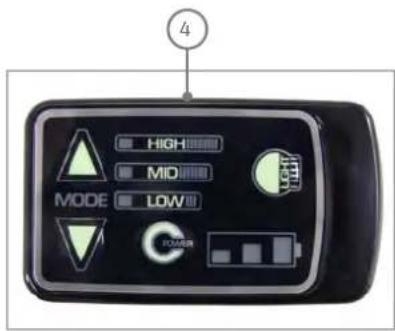
1 Power assist mode selection buttons
2 On/off (power) button
3 Button for lights
The control panel on the handlebar has three buttons and several display panels.
The display panel on the right next to the upper "Mode" button shows the level of active assistance via LEDs.
The "Power" button and corresponding display panel is below this.
Press the "Power" button to switch the power assist on and off.
The battery charge state is indicated by the LEDs next to this button. All three LEDs light up for two seconds when the power is switched on.
| DISPLAY(AFTER 2 SECONDS) | BATTERY CHARGE STATE |
| 3 LEDs light up ⋯ 70–100% | |
| 2 LEDs light up ⋯ 40–70% | |
| 1 LED lights up • 10–40% | |
| 1 LED flashes slowly ○ | < 10%At this point you notice a slight loss of power. |
| 1 LED flashes quickly ○ | ~ 0%The system shuts down shortly afterwards. |
You can specify the power assist level via the "Mode" buttons. The LEDs next to the top button show the level of assistance you are currently receiving from the motor.
All three LEDs light up for two seconds when the power is switched on.
Please do not put your feet on the pedals during this time.
The power sensor is reset each time the power is switched on in order for the power supply to the motor to be precisely controlled. A load must not be applied to the sensor during this two second period.
The intermediate assist level is subsequently selected automatically.
| DISPLAY LEDs ASSIST LEVEL RATIO | ||
| HIGH powerful 1:2 | ||
| MID intermediate | 1:1 | |
| LOW | gentle | 1:0.5 |
Each time you press the "Mode" button the power assist changes by one level. If you require more assistance, press the "Mode" arrow that points upwards. If you require less assistance, press the "Mode" arrow that points downwards.

Increase power assist
Once the highest level has been reached, the system jumps to the lowest assist level the next time the button is pressed and then moves back up through the levels.
If you require less assistance, press the "Mode" arrow that points downwards.
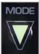
Reduce power assist
The assistance reduces in stages; when you reach "LOW" (the lowest assistance level) it jumps back "HIGH" (the highest assistance level).
4.1 Switching the light on and off

Button for lights
Press the button shown above to switch the Pedelec lighting on and off.
If you are riding with the lights on and switch off the assistance, the lights also switch off automatically. You must therefore switch the lights on again.

You must always take the battery with you, even if you want to ride without assistance as the lights will only work with the battery.
4.2 Automaticswitch-off
If you stop and do not move your Pedelec for 10 minutes, the system switches off automatically. If you subsequently want to ride using the assistance, you will have to switch it back on via the control panel.
5 Assistance by the electric motor
5.1 Operating principle of assistance
The motor provides support as soon as you switch the assistance on and start pedalling.
The thrust delivered by the motor depends on three factors:
- Your own pedalling effort
The motor adapts to the force you apply. If you pedal harder, e.g. uphill or when setting off, the power sensor detects this and increases the thrust accordingly. However, the thrust is limited by the maximum motor output.
•The assist level you have selected
With the "high assist level/HIGH" the power delivered by the motor is double your own effort (1:2). With the "medium assist level/MID", the power delivered by the motor matches your own effort (1:1). With the "low assist level/LOW/ECO", the power delivered by the motor is half your own effort (1:0.5).
The speed at which you are currently travelling
When you set off on your Pedelec, the assistance increases as you build up your speed until your bike reaches its maximum speed of roughly 19 km / h. The assistance then reduces automatically and switches off at roughly 25 km / h. This happens irrespective of the gear you are using.
Distance
The distance you can travel using the power assist with the battery fully charged depends on several factors:
•Ambient temperature
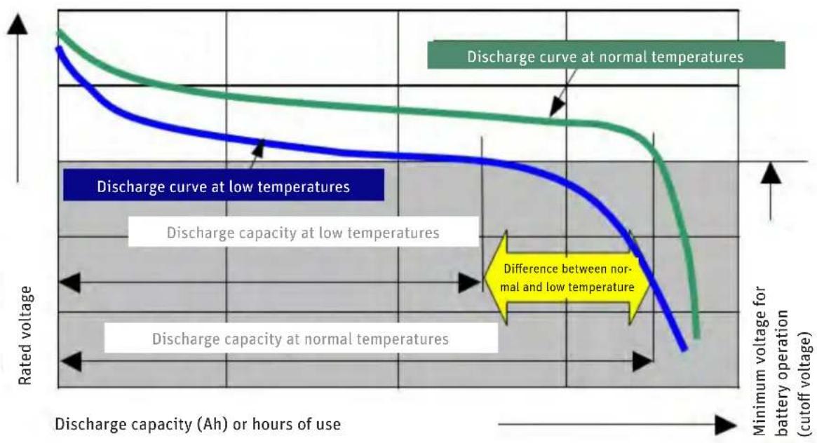
If it is colder, you will travel a shorter distance with the same battery charge.
To maximise the distance you can travel, keep the battery in a heated room so that it is at room temperature when you fit it on your Pedelec.
As the battery discharges when the motor is in use, it generates enough of its own heat to not lose too much of its power at low temperatures.
- Selected assist level
If you want to cover a large distance assisted by the motor, select the lower gears, i.e. the ones that are easier to pedal. Also change to "low assist level/LOW".
- Handling
If you are riding in gears that are harder to pedal and select a high level of assistance, e. g. when riding uphill, the motor will provide support with plenty of power. However, this leads to higher consumption, as with driving a car at high speed on the motorway. You will therefore have to recharge the battery sooner. You can conserve energy when riding your bike not just by turning the pedals, but also by applying even pressure throughout each crank revolution.

line
| Speed (km/h) | Propulsive power | Power assist mode (km/h) | Support/Resistance | | ------------ | ---------------- | ------------------------ | ------------------ | | 0 | High | 1.0 | Increasing | | 19 | Low | 2 | Reducing | | 25 | Low | 2 | Switched off |Variation in electric assistance
line
| Discharge condition | Description | | --- | --- | | Normal | Discharge curve at normal temperatures | | Low | Discharge curve at low temperatures | | Normal | Discharge capacity at normal temperatures | | Low | Discharge capacity at low temperatures | | Normal | Difference between normal and low temperature | | Low | Discharge capacity at low temperatures |Rate of discharge at different temperatures
•Technical condition of your Pedelec
Make sure the tyre pressure is correct. If you ride your bike with too little air in the tyres, this can significantly increase the rolling resistance. The distance you can travel also decreases if the brakes are rubbing.
•Ascents
You pedal harder when riding uphill. This is detected by the power sensor which then allows the motor to work harder.
Under ideal conditions, you can cover roughly 140 km with the battery fully charged (18 Ah). You can expect to cover a distance of roughly 85 km using different modes of operation.
DISTANCE COVERED (1:1 ASSISTANCE, 22 KM / H ON AVERAGE UNDER FAVOURABLE CONDITIONS)
| 8 Ah battery 60 km |
| 12 Ah battery 90 km |
| 18 Ah battery 140 km |
Distance covered using different batteries
5.2 Riding your Pedelec efficiently
You can monitor and influence the cost of your journeys with the Pedelec yourself. You can reduce your consumption and therefore costs by following the tips for increasing the travel distance.
The operating costs of power assist with an 18 Ah battery work out as follows:
• A new battery costs around 599 euro.
- You can cover 112 km on average with one battery charge. You can charge the battery roughly 1,100 times.
•1,100 charging cycles x 112 km = 123,200 km
•599 euros: 123,200 km = 0.47 euro cents / km
- You use roughly 0.620 kWh to fully charge the battery. Assuming a unit price of 20 euro cents / kWh, it costs you 12.4 euro cents to fully charge the battery and cover a journey length of 112 km.
- It costs you 0.20 euro cents / km to travel the minimum distance of 60 km.
- It costs you 0.09 euro cents / km to travel the maximum distance of 140 km.
- This means the cost of consumption and the battery is a maximum of 0.67 euro cents / km.
As Derby Cycle is a German manufacturer, the sample calculation is based on German energy prices. The operating costs may therefore be different in locations where other energy prices apply.
6 Battery
Your battery is a lithium cobalt battery, the ideal type of lithium-ion (Li-ion) battery for this application. One of the main benefits of this type of battery is its low weight combined with a high capacity. Li-ion batteries only weigh half as much as comparable nickel metal hybride or nickel-cadmium batteries. This means you carry less battery weight and more battery power.
6.1 Straightforwardcharging
There is no memory effect. You can therefore fully recharge your battery after every trip.
Recharge the battery after every trip. This means you can set off immediately the next time you use your bike and you also increase the service life of the battery.
If you are not using the battery, you must recharge it after 6 months at the latest.
6.2 High degree of safety due to battery management
The battery cannot be damaged as a result of a short-circuit. If this were to happen, the battery management would switch off the battery.
You can simply leave the battery standing in the charger as it prevents overcharging.
6.3 Straightforwardstorage
If you do not need your battery for a while, store it at a temperature of +10 °C at three quarters of its full charge capacity.
The battery enters sleep mode to prevent it from totally discharging.
These benefits are available due to highly effective battery management that has been adapted to this specific application and by tuning the battery for operation with a 250 watt motor.

Observe the following points to increase the service life of your Pedelec battery:
Make sure that the battery is fully charged before you ride your bike for the first time or after you have not used it for a while.
You should run the battery all the way down to empty for the first three charging cycles. This allows the battery to reach its maximum capacity.
If you continuously run the battery to empty during normal operation, this reduces its service life.
If you partially recharge the battery frequently during normal operation, this has a favourable effect on its service life.
You should therefore partially recharge the battery whenever possible: Try not to run the battery all the way down to empty and recharge it even after a short period of operation.
In the as-delivered condition, the battery is not fully charged and is in what is referred to as sleep mode. Sleep mode minimises the rate at which the battery discharges itself. If the battery is allowed to discharge unchecked for an extended period this can lead to total discharging which damages the battery. To "wake up" the battery, simply place it in the charger for one minute.
If you are having problems with the battery, place it in the charger for one minute. A reset occurs, during which the battery management disables sleep mode for example. After this, the battery will work again.
Ideally you should charge the battery at a temperature of between +10 °C and +30 °C. It takes longer to charge the battery at low temperatures, the battery will not charge up at temperatures higher than +30 °C. Ideally, you should charge and store the battery inside your house or in a warm garage when the outside temperature is low. In this case you should only fit the battery on your bike just before using it.
If you are transporting your Pedelec by car, take the battery out of its holder and transport it separately.
The battery is ideally stored for longer periods charged to 75% of its capacity at a temperature of +10°C.

flowchart
graph LR
    A["Long charging times"] --> B["Optimum temperature range for charging operation"]
    B --> C["Battery may be damaged"]
Charging times at different temperatures
6.4 Battery information system
There is a control panel with five LEDs and a button ("Push") on the side of the battery that faces outwards. The LEDs light up if you press the "Push" button. Information about the battery and its charge state is provided based on the number of LEDs that light up and the way in which they light up.
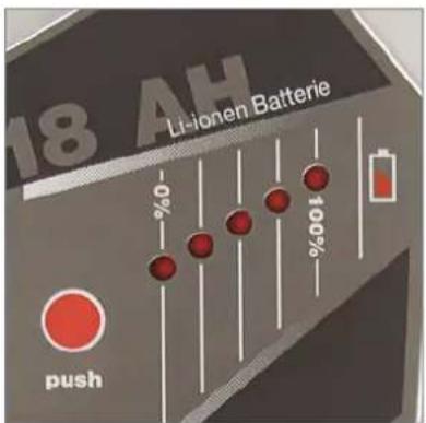
Charge state and battery capacity indicator
6.4.1 Checking the battery charge state
Press the "Push" button briefly, the LEDs light up and display the current battery charge state.
| DISPLAY BATTERY CHARGE STATE | |
| 5 LEDs light up ······ 80-100% | |
| 4 LEDs light up ······ 60-80% | |
| 3 LEDs light up ···· 40-60% | |
| 2 LEDs light up ···· 20-40% | |
| 1 LED lights up · | 10-20% |
| 1 LED flashes ○ | <10% |
| no display - | 0% |
| E: Battery is empty | |
| F: Battery is full | |
6.4.2 Checking the battery capacity
If you press the "Push" button for longer than five seconds, the LEDs show the current capacity of the battery.
| DISPLAY CAPACITY |
| 5 LEDs light up ······ 100-80% |
| 4 LEDs light up ······ 80-60% |
| 3 LEDs light up ···· 60-40% |
| 2 LEDs light up ···· 40-20% |
| 1 LED lights up · 20-0% |
Capacity of 18 Ah battery (example)
Check there is sufficient charge in the battery for the journey you intend to make before setting off.
In winter the distance you can normally cover with the battery operating normally is less. Only move the battery from the warm room where you store it and fit it on your Pedelec just before you set off. This prevents low temperatures from reducing the distance you can normally travel. A corresponding diagram is provided in Chapter 12 "Technical data"
The distance you cover can vary depending on the topography, your handling, the condition of the battery and the assist level you are using.
If all diodes flash consecutively, or several flash at the same time (2 - 3 diodes), the battery is damaged.

Before taking the battery to your specialist cycle shop to have it checked, put the battery in the charger for one minute then test it again.
6.5 Service life and warranty
6.5.1 the electric drive
The Panasonic front electric drive is a fully-developed durable and maintenance-free electric drive. It is a wear part for which a two-year warranty applies.
6.5.2 thebattery
Batteries are wear parts. Wear parts also come with a two-year warranty.
If the battery develops a fault during this period, your specialist cycle shop will of course replace it. A fault does not constitute normal ageing and battery wear.
The service life of the battery depends on different factors. The most important wear-relevant factors are
• the number of charge cycles and
• the age of the battery.
When you have fully charged and discharged your battery 1,100 times, it will still have 60% of its initial capacity, providing it has been well looked after:
| BATTERY | REMAINING CAPACITY | ~ DISTANCE COVERED |
| 8 Ah 4.8 Ah 19,360 km | ||
| 12 Ah 7.2 Ah 30,800 km | ||
| 18 Ah | 10.8 Ah | 52,800 km |
From a technical standpoint therefore, the battery is "used" at this point. It also goes without saying that the battery ages. Even if you do not use your battery, its capacity reduces.
Providing you can still cover the journey distances with this remaining battery capacity, you can of course continue using it. If the capacity is no longer sufficient, you can take your battery to a specialist cycle shop who will dispose of your battery and supply you with a new one.
You can extend the service life of the battery by fully recharging it after every journey, even if it is small. The Panasonic li-ion cobalt battery has no memory effect.
You can also extend the service life of the battery by using the assistance selectively. Avoid, for example, using gears that make pedalling difficult with the most powerful assist level.
7 Charger
Read the two stickers on the charger before using it for the first time.

Do not use other chargers. Only charge the battery using the charger provided, or a charger approved by Derby Cycle.
If a fault develops or if the battery is in sleep mode, you might be able to solve this problem by placing the battery in the charger for one minute. The battery management then checks the battery and can eliminate any faults that have occurred.

If used incorrectly, the device may be damaged or inflict injuries.
Before cleaning the charger, always pull the plug out of the socket to avoid a short-circuit and/or physical injury.
Only use the charger in dry rooms.
Only place the charger in a secure stable position on a suitable surface.
Do not cover the charger or place any objects on it as otherwise it could overheat and catch fire.
8 Troubleshooting
The control panel also indicates when faults and technical errors are present. If a fault occurs, the LEDs flash in a specific pattern and with a specific rhythm. This indicates the cause of the problem and makes it easier for you to find a solution.

Control panel display

Have the electric drive inspected regularly by your specialist cycle shop. Do not carry out any work on the electric drive or battery yourself. Unless you have sufficient expertise this could lead to a serious accident. As a basic rule, always consult your specialist cycle shop if you have a problem with the electric drive or the battery.

You should only have the electrical components of your Pedelec replaced with genuine parts. This makes it safer for you and avoids problems when processing warranty claims.
8.1 Problems/solutions: Flash patterns and their meaning
If a problem occurs in the electrical system of your Pe-delec, you should initially try to solve it by referring to the following list which describes possible causes of errors and offers solutions. If the fault persists, consult your specialist cycle shop.
ERROR CODE CAUSE SOLUTION
 | 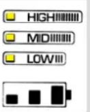 |  | 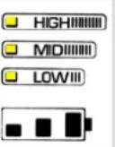 | No power assist. The power sensor could not set itself correctly. | Perform restart. The system performs the calibration again. No force should be applied to the pedals during this procedure which takes roughly two seconds. | |
 | 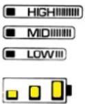 |  | 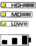 | HIGHMIDLOWII | No power assist. A problem occurred in the drive unit. | Motor, sensor unit or cable defective. Contact your specialist cycle shop. |
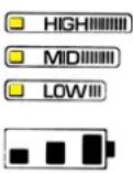 |  |  | 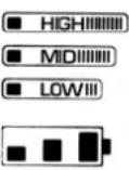 | The motor output is less.The motor is overloaded. | Allow the motor to cool down and reduce the assistance. | |
 |  | 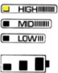 | 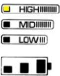 | The motor switches off.The motor is extremely overloaded. | Allow the motor to cool down and reduce the assistance. | |
 |  |  |  | No power assist.The battery is nearly empty. | Charge the battery immediately. |
8.1.1 Additional possible sources of errors
If you only pedal very gently, the power assist is not enabled.
If the motor is not running and you cannot pinpoint the cause, check the buttons, cables and plugs of the electrical system.

If you find a break or a crack, do not try to repair the fault yourself. Take your Pedelec to a specialist cycle shop.
9 Removing the front wheel
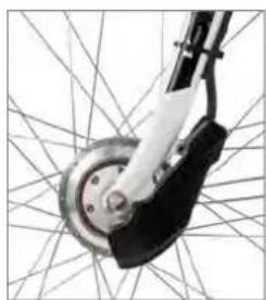
As the motor is built into the front wheel, you must perform the following steps before you can remove the front wheel:
Take the battery out of the Pedelec.

Always remove the battery before removing the front wheel and carrying out any subsequent work on the motor as otherwise you could injure yourself.
Undo the two small hexagon socket screws on the plastic cover that is fitted to the left of the front wheel by turning them anticlockwise using a 3 mm Allen key. Keep these in a safe place. Slide the cover to the left and take it off the fork.

natural_image
Mechanical component with labeled parts, showing a wheel and linkage assembly (no text or symbols present)1 + 2 Hexagon socket screws
Once the cover is removed, you should now be able to see one white and one green cable connector. Open these connectors and pull them apart.

natural_image
Mechanical assembly diagram showing a wheel and brake components with labeled parts (1 and 2), no readable text or symbols beyond labels.1 Green connector
2 White connector
To open the white connector, push a sharp object (tip of a key or ball point pen) down onto the angled surface of the snap-in mechanism, as shown below. You can pull the two connector halves apart when pushing this surface back.

natural_image
Close-up of hands assembling a mechanical component with wires and a green connector (no visible text or symbols)White connector
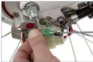
To open the green connector, push a flat pointed object (small screwdriver or small point of a key) under the small tab. You can disconnect the two connector halves while lifting the tab.
natural_image
Close-up of a hand using a tool to adjust or install a small electronic component (no visible text or symbols)Green connector
The cables leading to the two connectors, exit from a black plastic tube just in front of the two connectors. At this point, they are joined together with metal braiding inside a metal clamp and fastened with a crosshead screw. Unscrew and remove the small screw by turning it anticlockwise.

natural_image
Close-up of a bicycle wheel assembly with visible wiring and components (no text or symbols)Base plate with cables and connectors
Undo the two hexagon socket screws on the left behind the fork using a 5 mm Allen key. You need to turn them anticlockwise.

Apply a max. tightening torque of 9.5 Nm to these screws when putting the wheel back on

1 + 2 Hexagon socket screws on the fork
You can now start removing the front wheel.
Once you have put the front wheel back on, repeat these steps in reverse. This ensures that your Pe-delec will work properly.
For a detailed description on how to remove and install the front wheel, refer to the General User Manual.
The General User Manual also contains all other bicycle-related information on your Pedelec.
10 Cleaning

Remove the battery before you clean your Pedelec.
We recommend you clean your Pedelec with a damp cloth, a sponge or a brush. You can obtain suitable cleaning agents and additional information from your specialist cycle shop.
Make sure when cleaning that water does not enter the battery. Although the electrical components are sealed, it is not advisable to clean the bike by spraying it with a hose or a high-pressure cleaner. This could damage your bike.
When wiping down the battery, be careful not to touch and connect the contacts on the underside. This could cause the battery to switch off.
11 Warnings

Bear in mind that the Pedelec motor can heat up on long ascents. Be careful not to touch it with your hands, feet or legs as you could burn yourself.
The Pedelec operates using low voltage (25.2 volts). Never attempt to operate the Pedelec using power from a source other than a suitable genuine battery. The designations of approved batteries are listed in Chapter 12 "Technical data".
Live parts may be exposed when you open covers or remove parts. Connection points may also be live. Maintenance or repairs on the device when it is open and connected to the power supply must only be carried out by the specialist cycle shop.
When carrying out adjustments and maintenance or when cleaning the Pedelec, avoid crushing cables or damaging them with sharp edges.
If risk-free operation of your Pedelec cannot be assumed, take it out of operation and make sure it cannot be used until you have it checked by a specialist cycle shop. Risk-free operation is no longer possible if live parts or the rechargeable battery show signs of damage.
Keep children away from electrical appliances. If children are present, keep a close eye on them, especially if they could insert objects into the appliance through apertures in the housing as this poses the danger of fatal electric shock.
12 Technicaldata
| MOTOR | |
| Hub motor with planetary gear | |
| Output 250 watts | |
| Maximum torque 16 Nm | |
| Gross weight of electric drive, battery, control unit | 7.0 kg (12 Ah battery) |
| Control via power sensor | |
| Assist levels | 1:0.5 | 1:1 | 1:2 |
| Speed of front wheel, at which the assistance switches off | 202 rpm |
| PANASONIC LI-ION BATTERY |
| Voltage 25.2 V |
| Capacities 8/10/12/18 Ah |
| Energy quantity 200/250/300/450 Wh |
| DCWITEM NO. | ITEM NO. | CAPACITY[AH] | WEIGHT[KG] | POSSIBLE APPLICATION | ||
| CENTRE FAST FRONT | ||||||
| 17017002 | NKY226B02 | 10 | 2.4 | X | 250 W | - |
| 17017012 | NKY226B02 | 10 | 2.4 | X | 250 W | - |
| 17019018 | NKY252B02 | 10 | 2.4 | - | - | X |
| 17019103 | NKY252B02 | 10 | 2.4 | - | - | X |
| KD170110010 | NKY266B02 | 10 | 2.4 | X | 250 W | - |
| 170110010 | NKY266B02 | 10 | 2.4 | X | 250 W | - |
| 170110003 | NKY265B02 | 10 | 2.4 | - | 300 W | - |
| 170110016 | NKY267B02 | 10 | 2.4 | - | - | X |
| 170111002 | NKY284B2 | 10 | 2.4 | X | 300 W | X |
| 170111200 | NKY306B2 | 8 | 1.9 | X | 300 W | X |
| 170111201 | NKY304B2 | 12 | 2.6 | X | 300 W | X |
| 170111202 | 14069 | 18 | 3.1 | X | 300 W | X |
Possible applications of batteries

line
| Temperature | Capacity (%) | | :--- | :--- | | -10°C | 86.5 | | 0°C | 94.3 | | 20°C | 100.2 | | 40°C | 97.8 |Capacity curve at different temperatures
We hope you thoroughly enjoy using your new Pedelec!
Copyright © 2012 Raleigh Univega GmbH
Reproduction in whole or in part is not permitted without the consent of Raleigh Univega GmbH. Subject to misprints, errors and technical modifications.
V
User Manual Impulse Pedelec
English

natural_image
Exterior view of a modern bicycle with visible 'PALESIEN' branding and front wheel (no additional text or symbols)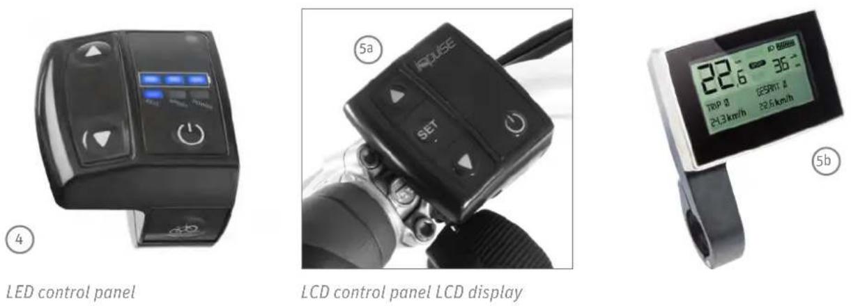
natural_image
Two electronic devices connected by wires, one with a label and the other with a logo (no visible text or symbols on the devices themselves)Charger
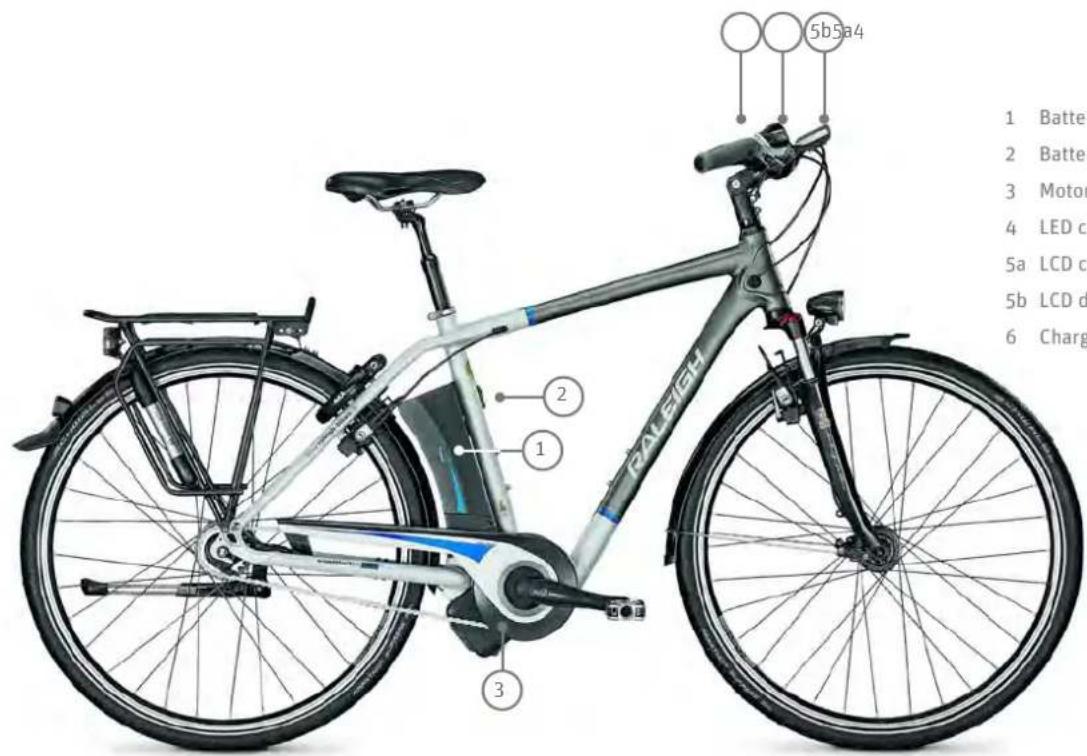
1 Battery
2 Battery lock
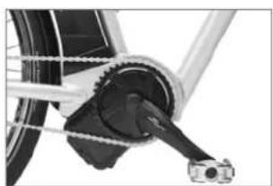
3 Motor unit
4 LED control panel
Sa LCD control panel
5b LCD display
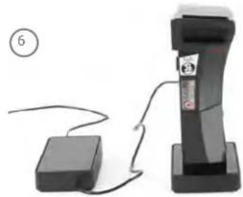
6 Charger
Dear Customer,
Thank you for choosing a Pedelec (pedal electric cycle) featuring the innovative Impulse drive from our company. This bike is equipped with an electric drive that assists you when you are cycling. This will make your trip much more enjoyable if you are riding up hills, carrying loads or riding into the wind. You can decide yourself how much you want to use it. Your Pedelec is the first in the world to feature a combination of centre motor and back-pedal brake. The purpose of this User Manual is to help you get the most out of your Pedelec and use it correctly.
Structure of User Manual
If you want to get started right away, refer to the brief introduction in ➔ Chapter 1 "Quick start".
The individual steps are subsequently explained in detail, supplemented by illustrations and diagrams.
More detailed information on your Pedelec is provided in Chapter 11 "Technical data".
The information in this User Manual specifically refers to your Pedelec only. For general information, on the bike technology that features in your Pedelec for example, refer to the General User Manual.

Even if you can't wait to go for your first ride, in the interest of your own safety you should read ➔ Chapter 1 "Quick start" carefully without fail before use.
In addition to texts and tables, the User Manual contains the following symbols that denote important information or dangers.

WARNING about possible physical injury, increased risk of falls or other injuries

IMPORTANT ADDITIONAL INFORMATION or special information on using the bike

NOTE regarding possible damage to property or the environment
Contents
EC Declaration of Conformity
2012 6
2013 7
1 Quick start 9
2 Legal principles 10
2.1 Meaning for the rider 10
2.2 Pushing assistance 10
3 Special features of the Pedelec with Impulse drive 10
4 Charging the battery 12

4.1 Learning cycle 12
4.2Chargingoperation 13
4.3 Fitting the battery 13
5 Control panels 14
5.1 LED control panel 14

5.1.1 On/Offbutton 14
5.1.2 Buttons for power-assist level 15
5.1.3 Display of the power-assist mode 15
5.1.4 Battery charge state indicator 16
5.1.5 Troubleshooting 16
5.2 LCD control panel with display 18
natural_image
Close-up of a black electronic device with control buttons and a rotary knob (no visible text or symbols)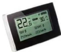
5.2.1 On/Offbutton 19
5.2.2 Buttons for power-assist level 19
5.2.3 Display of the power-assist mode 19
5.2.4 Battery charge state indicator 19
5.2.5 Remaining range indicator 20
5.2.6 Troubleshooting 20
5.2.6.1 Condensationappearing on the LCD display 20
5.3 Setting and programming the LCD display 21
5.3.1 Delete trip data/ Delete overall data 21
5.3.2 Devicesettings 21
5.3.2.1 Contrast 21
5.3.2.2Brightness 21
5.3.2.3Language 21
5.3.2.4 Wheelcircumference 22
5.3.2.5Unit 22
5.3.2.6 Name 22
5.3.2.7 Factorysettings 22
5.3.2.8 Software 22
5.3.3Costspecifications23
5.3.3.1 Fuelprice23
5.3.3.2Electricitycosts23
5.3.3.3 Fuel consumption 23
5.3.3.4 Fueltype 23
5.3.3.5Back 23
6 Assistance by the electric motor
natural_image
Close-up of a bicycle's wheel and suspension mechanism (no text or symbols visible)6.1 Operating principle of assistance 24
6.2 Distance 25
6.3 Riding your Pedelec efficiently 25
7 Battery 26
7.1 Straightforwardcharging 26
7.1.1 Learning cycle 26
7.2 High degree of safety due to battery management 26
7.3 Straightforwardstorage 26
7.4 Battery information system 28
7.4.1 Checking the battery charge state 28
7.4.2 Checking the battery capacity 28
7.5 Service life and warranty 29
7.5.1 of the drive 29
7.5.2 of the battery 29
8Charger30
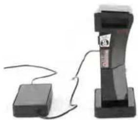
natural_image
Simple electrical device with a battery and cable, no visible text or symbols9Cleaning31
10Warnings31
11Technicaldata32
EC Declaration of Conformity 2012 CE
The manufacturer: Raleigh Univega GmbH
Siemensstraße 1–3
49661 Cloppenburg, Germany
Telephone: +49 (0) 4471/9234-0
hereby declares that the following products:
Product description: Raleigh Pedelec Panasonic
Model designation:
Dover de Luxe 7G, Dover de Luxe 8G, Dover 3G, Dover Premium 8G, Leeds Sport 11G, Leeds HS 8G, Leeds Roller, Leeds Tour 7G, Stoker Lite Premium, Stoker 360, Stoker Lite 8G, Stoker DD, Dover LTD, Dover XXL LTD
Product description: Raleigh Impulse
Model designation:
Dover 125th Impulse, Dover Premium Impulse, Dover XXL Impulse, Dover HS Impulse, Impulse XXL, Impulse, Impulse HS, Impulse Compact, Leeds Compact, Dover Impulse
Product description: Raleigh Groove
Model designation:
Groove F3, Groove F8
Product description: Raleigh BionX
Model designation:
Blackburn 7, Blackburn 5, Blackburn 3
Product description:
Raleigh Bosch Pedelec
Model designation:StokerB
Year of manufacture:
2012
comply with all of the relevant requirements of the Machinery Directive (2006/42/EC).
Furthermore, the machine complies with all of the requirements of the Electromagnetic Compatibility Directive (2004/108/EC).
The following harmonized standards have been applied:
DIN EN 15194 Cycles – Electrically power-assisted cycles – EPAC cycles
DIN EN 14764 City and trekking bikes – Safety requirements and test methods
Technical documentation filed at:
49661 Cloppenburg, Germany

Olaf Flunkert
Production, Purchasing and
Technology Manager
M. K. Chen Hoge
Karl-Heinz Lange
Design and Development Manager
49661 Cloppenburg, Germany
21.09.2011
EC Declaration of Conformity 2013 CE
The manufacturer: Raleigh Univega GmbH
Siemensstraße 1–3
49661 Cloppenburg, Germany
Telephone: +49 (0) 44 71 / 92 34 - 111
hereby declares that the following products:
Product description: Raleigh Pedelec Panasonic
Model designation: Dover de Luxe P8 36V, Dover de Luxe P8R 36V, Dover de Luxe P8 26V, Dover de Luxe 8G 26V, Dover de Luxe 7G 26V, Dover de Luxe 2x8 8G, Leeds Sport
Product description: Raleigh Impulse Pedelec
Model designation: Impulse iR, Impulse iR HS, Impulse iR Classic, Impulse iR Premium, Impulse iR XXL, Impulse iR Compact, Stocker i11 Di2, Stocker i Light Premium, Stocker iR Light, Stocker IDD, Leeds i Light, Leeds i HS, Leeds iR HS, Leeds i Roller, Leeds iR Tour, Leeds I Compact, Dundee iR Cargo, Dundee i Compact, Dover i, Dover I HS, Dover i XXL, Dover i Premium, Dover i360, Dover i360 Harmony
Product description: Raleigh Groove Pedelec
Model designation: GrooveF8
Product description: Raleigh Xion Pedelec
Model designation: Blackburn 5, Blackburn 3
Product description: Raleigh Bosch Pedelec
Model designation: Stoker B8, Stoker B9
Year of manufacture: 2013
comply with all of the relevant requirements of the Machinery Directive (2006/42/EC).
Furthermore, the machine complies with all of the requirements of the
Electromagnetic Compatibility Directive (2004/108/EC).
The following harmonized standards have been applied:
DIN EN 15194 Cycles – Electrically power-assisted cycles – EPAC cycles
DIN EN 14764 City and trekking bikes – Safety requirements and test methods
Technical documentation filed at:
49661 Cloppenburg, Germany

Olaf Flunkert
Production, Purchasing and
Technology Manager
Mard-Heni Hoge
Karl-Heinz Lange
Design and Development Manager
49661 Cloppenburg, Germany
14.05.2012
1 Quickstart
-
Charge the battery completely before riding for the first time. Charge temperature: 0 - 45°C
-
Swivel the round charging socket cover on the battery to one side.

natural_image
Close-up of a mechanical component with a circular socket and mounting holes (no visible text or symbols)Now insert the four-pole plug of the charger into the battery charging socket.
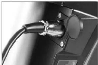
natural_image
Close-up of a black cable inserted into a mechanical component (no visible text or symbols)Charging the battery
- Insert the mains plug for the charger into the socket.
You must fully charge the battery before using it for the first time.
- Once all LEDs on the battery have gone out, pull the charger plug out of the battery socket. Swivel the cover back over the charging socket.
You can also remove the battery from your Pedelec and charge it in the docking station. For more information, refer to ➔ Chapter 4 "Charging the battery".
-
If you have charged the battery in the docking station, reinsert the battery into the holder on the Pedelec from the left-hand side. Tilt the battery outwards at an angle of roughly 45^ as you do so, as you did when you took it out of the holder. Move the battery into the upright position until the locking mechanism engages. If the key is still in the lock, you will need to turn it clockwise and pull it out as otherwise the battery will not lock in place.
-
Make sure that the battery is securely positioned and that the key is no longer in the lock.
If your Pedelec is equipped with an LCD control panel:
-
Push the Power button on the control panel on the handlebar.
-
The display panel now displays the medium power-assist mode SPORT. Press the arrow buttons to select the level of assistance: STAND BY (off), ECO (low), SPORT (medium) or POWER (high). Press this button once to change the level of assistance by one level. This works both ways, depending on which arrow button you press.
The following applies for bikes which are equipped with a back-pedal brake:
- The system will now perform a system check. "Please move the pedals" will appear on the screen. If you set off now the system will normally detect a pedal movement in the "drive" and "backpedal brake" directions. This completes the safety check, and you can ride as normal with assistance.
If you cannot feel any assistance, simply back-pedal briefly and then pedal forwards again to trigger the system check. If there is still no assistance being delivered, the instruction "Please move the pedals" will continue to be displayed. In this case you should consult a specialist dealer.

You can now ride off just as you would if you were riding a normal bike. The motor starts providing assistance as soon as the rear wheel starts turning.
2 Legalprinciples
The essential idea behind the Pedelec is not only to be able to cover greater distances more quickly, but also more comfortably. You can choose to relax and let the bike do the work, exert yourself more physically, or simply get from A to B as fast as possible. You can decide this yourself by choosing an appropriate assist level.
This gives you more confidence on the road, as the powerful acceleration gives you more control and a greater degree of security. Your Pedelec assists you with an output that adapts to your pedalling force up to roughly 25 km/h.
In some EU countries, the Pedelec, like all other bikes, must comply with certain regulations, the Road Traffic Licensing Regulations (StVZO) in Germany for example. Please observe the relevant explanations and general information provided in the General User Manual.
These statutory requirements apply for a Pedelec:
- The motor is designed only to provide pedalling assistance, i.e. it can only "assist" the rider when he/she turns the pedals.
•The average motor output must not exceed 250 W. - As the speed increases, the rate at which the motor output reduces must also increase more intensely.
- The motor must switch off once the bike reaches a speed of 25 km/h.
2.1 Meaning for the rider
- You do not legally have to wear a helmet. In the interest of your own safety, however, you should never ride without a helmet.
- You do not legally have to have a driving license (unless you own a model with pushing assistance, Chapter 2.2 "Pushing assistance").
- You do not legally have to have insurance.
- No age restriction applies for a Pedelec.
• The regulations governing the use of cycle paths are the same as for normal bikes.
These regulations apply to you wherever you are in the European Union. It is possible that different regulations exist in other countries, also inside the EU in individual cases. Before using your Pedelec abroad, find out about the legal situation in the relevant country.
2.2 Pushingassistance
Your Pedelec is available in a version with or without pushing assistance. Your specialist cycle shop can retrofit a control panel with pushing assistance if required.

natural_image
Close-up of a black DSLR camera with a circular logo on the grip (no visible text or symbols)Button for pushing assistance
The pushing assistance moves the Pedelec slowly (at a maximum speed of 6 km/h) without you having to turn the pedals, e.g. if you are manoeuvring in a tight space or are pushing your Pedelec out of a basement garage.
If you were born after 01. 04. 1965, you will need a moped test certificate for the version with pushing assistance. If you already have another type of driving licence, this automatically includes the moped test certificate.
The pushing assistance is not suitable for use as starting assistance.
3 Special features of the Pedelec with Impulse drive
Your Pedelec has special features that are designed to enhance your safety and comfort, some of which are unique worldwide.
The Impulse drive has been developed exclusively to allow a centre motor to be installed without having to dispense with the safety and convenience of a back-pedal function.
This means you can rely on three brakes; the familiar back-pedal brake and the powerful, modern rim brakes.

1 Rim brake, front
2 Back-pedal brake
3 Rim brake, rear
With the Impulse drive, the amount of assistance can be increased by selecting easier gears, when starting or riding uphill for example. The motor produces more power when your pedalling cadence is higher.
You can conveniently use the same key to lock/unlock your battery and, where present, your frame lock.
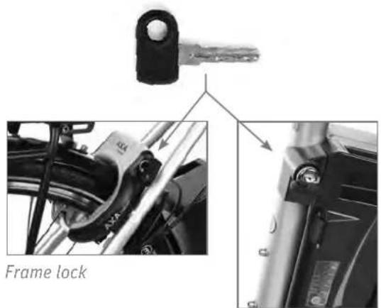
Battery lock
In contrast to a hub motor, the Impulse centre motor centre motor drive allows you to ride within the motor range that saves the most power or, if required, the range in which the highest output is available.

line
| Speed (km/h) | Output | | ------------ | ------ | | 0 | 0 | | 10 | ~1.5 | | 20 | ~3.0 | | 30 | ~4.5 | | 40 | ~5.5 | | 50 | ~6.0 | | 60 | ~6.5 | | 70 | ~7.0 | | 80 | ~7.5 | | Max. speed | 0 |Output curves of the centre motor
Output curve of the hub motor
You can decide how you wish to put in your effort:
In the three highest gears, you can ride up to a maximum speed of 25 km/h assisted by the motor. You can, for example, go for a relaxed ride on the flat with a low pedalling cadence. However, you can also ride uphill using an easier gear and less energy, simply by making the most of the highest assisted speed. You should therefore either turn the pedals more slowly (low cadence) with more effort or turn them more quickly (high cadence) with less effort.
| OTHER CENTRE MOTOR | DRIVE | |||
| GEAR | CRANK REVOLU-TIONS/MIN. | SPEED (KM/H) MOTOR SPEED | CRANK REVOLU-TIONS/MIN. | SPEED (KM/H) MOTOR SPEED |
| 1 | 71 8 3,000 | 86 12 4,300 | ||
| 2 | 71 10 3,000 | 86 13 4,300 | ||
| 3 | 71 12 3,000 | 86 15 4,300 | ||
| 4 | 71 13 3,000 | 86 19 4,300 | ||
| 5 | 71 16 3,000 | 86 22 4,300 | ||
| 6 | 71 19 3,000 | 85 25 4,200 | ||
| 7 | 71 | 22 3,000 73 | 25 3,650 | |
| 8 | 71 | 25 3,000 64 | 25 3,200 | |
The data provided is an example for the assistance function. The data may vary depending on the model.
4 Charging the battery
You can charge the battery whilst it is on the Pedelec (as described in ➔ Chapter 1 "Quick start").

natural_image
Black-and-white photo of a bicycle with attached rear panel and charging cable, no visible text or symbolsYou can also remove the battery from the holder and charge it in the docking station. This is recommended if it is cold outside, in order to charge the battery in a warm room. The battery can be charged at temperatures between 0 and 45°C.
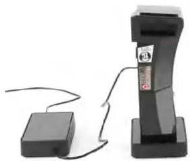
natural_image
Two electronic devices with cables connected by a cable, one black and one white (no visible text or symbols)
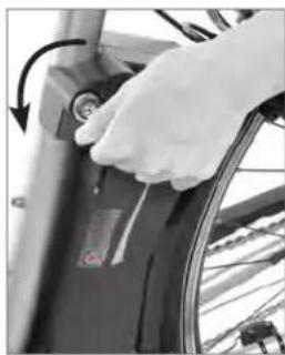
- Grip the battery by the handle, insert the key into the lock and turn it anticlockwise.
natural_image
Close-up of a hand adjusting a bicycle wheel component with a circular arrow indicating rotation (no text or symbols visible)Unlocking the battery
- Now the battery is unlocked and can be removed. To remove it, tilt the Pedelec to one side. In doing so, hold on tight to the battery to prevent it from being dropped.

natural_image
Close-up of a hand adjusting a bicycle wheel component (no visible text or symbols)Tilt when removing
- You should now remove the key and keep it in a safe place to prevent it from breaking off or being lost.
4.1 Learning cycle

After fully charging the battery for the first time and thereafter roughly once every six months, you must run the battery down until the system switches off. This procedure (a so-called "learning cycle") is necessary so that the battery management recognises the changes in the capacity caused by age and wear and tear, in other words, the performance level of the battery. Afterwards, the capacity of the battery is calculated anew and correctly represented. With this procedure, you can prevent a sudden loss of electrical assistance during an extended trip.
4.2 Chargingoperation
Before charging the battery, read the information on the charger carefully.
- Take the charger and docking station provided out of its packaging and plug the mains plug into a socket (230 V, please observe type plate on the charger).

natural_image
Two black electronic device modules with visible labels and a cable, shown from different angles (no readable text or symbols)Type plates on charger and docking station
To charge the battery safely, the charger must be placed on a suitable surface resting on its four feet with the LED facing upwards. This is the only way to ensure that the hot air around the battery warmed during the charging operation can dissipate via the surrounding ventilation slots.
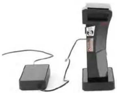
- Connect the charger to the docking station. The LED in the docking station now lights up briefly in red and then permanently in green.
- Put the battery in the holder of the docking station. The battery and charger are connected. The LED in the charger lights up in green.
natural_image
Two electronic devices: a black rectangular device connected to a small black box with wires, and a vertical black stand with a label (no visible text or symbols on the device body)Battery in the docking station
- The charging operation starts. The LED in the charger now lights up green. The battery LEDs light up one by one to indicate the progress of the charging operation. The battery is charged in five stages. When charging of one stage is in progress, the cor-
responding LED flashes. If this stage has been fully charged, the LED will light up permanently. Now the next LED will begin to flash.
After all five LEDs have gone out, the battery is fully charged.
- If the LED of the charger flashes red permanently, a charging fault has developed.

Take the battery out of the charger, then put it back in. The charger tests the battery and performs readjustments, if required. If the LED on the charger still flashes, take the charger and battery to your specialist dealer. He will test the devices and replace them, if required.
- To save power, pull the charger plug out of the socket once the charging operation is complete.
4.3 Fitting the battery
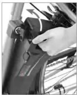
- Insert the battery into the battery holder of the Pedelec from the left by tilting it outwards at roughly 45°.
natural_image
Close-up of a hand adjusting a bicycle wheel component (no visible text or symbols)Reinstalling the battery
- Make sure in doing so that the lateral guides at the bottom of the battery are also inserted into the guides in the holder.
- Tilt the battery towards the bike until it engages in the locking mechanism. If the key is still in the lock, turn it clockwise then pull it out to lock the battery in place.
- Make sure the battery is firmly in place.
5 Control panels
When buying your Impulse Pedelec, there are two different control panels to choose from: with an LED or LCD display. With the LED display, lit diodes display the information for you, while more information is displayed with the LCD element. In addition, text and digits are shown on the display.
5.1 LED control panel

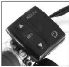
1 Buttons for power assist level
2 On/Off switch
3 Battery charge state indicator
4 Power-assist mode indicator
5 Button for pushing assistance (optional)
The control panel on the handlebar has three or four buttons (depending on the model) and two rows of LED indicators. The buttons used to control the level of assistance are located on the left-hand side of the control panel.
Above and to the right you can see the row of LED indicators that shows which level of assistance has been activated and the current battery charge state.

Row of LED indicators for charge state and assistance
The "Power" button is located below the LEDs. Press this button to switch the control panel on and off.
natural_image
Close-up of a black circular button with a white power symbol (no text or numbers visible)On/Off button
If the model features pushing assistance, the switch for this will be on the underside of the control panel.

natural_image
Close-up of a black DSLR camera with a circular logo on the side (no visible text or symbols)Button for pushing assistance
5.1.1 On/Offbutton
Press the "Power" button to switch the control panel on and off.
After it has been switched on, the system is always in the medium power-assist mode SPORT.
The following applies only to bikes which are equipped with a back-pedal brake:
The system will now perform a system check. At this time, the LED on the left will now come on for approx. two seconds, followed by all LEDs for approx. one second. If you set off now, the system will normally detect a pedal movement in the "drive" and "back-pedal brake" directions. This completes the system check, and you can ride as normal with assistance.

If you cannot feel any assistance, simply back-pedal briefly and then pedal forwards again to trigger the system check. In the event that the LEDs continue to flash in the pattern described above and the motor is not providing any assistance, then you should consult a specialist dealer.
5.1.2 Buttons for power-assist level
You can specify the power-assist level via the arrow buttons.

natural_image
Close-up of a black rectangular button with two circular buttons and a triangular pointer (no text or symbols visible)Buttons for power-assist level
Each time you press an arrow button the power assist changes by one level.
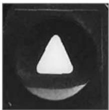
Each time you press the button with the arrow pointing upwards, the assistance increases by one level from "no assistance/stand by" through to the highest level: POWER.
natural_image
Abstract geometric shape resembling a white triangle inside a dark circular frame (no text or symbols)Increase power assist
Each time you press the button with the arrow pointing downwards, the assistance decreases by one level from POWER through to the no assistance level STAND BY.

natural_image
Black and white abstract shape resembling a triangle with a central oval (no text or symbols)Reduce power assist
5.1.3 Display of the power-assist mode
The bottom row of LEDs on the right of the display next to the buttons for selecting the power-assist level shows you how much assistance the motor is currently providing.
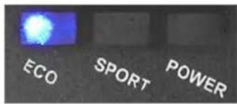
Display of power-assist mode
| DISPLAY ASSIST LEVEL | |
 | POWER: The LED on the right of the display will light up. This means the assistance is working hard. |
 | SPORT: The LED in the middle of the display will light up. This means the assistance is working with a medium level of effort. |
 | ECO: The LED on the left of the display will light up. This means the assistance is working with a low level of effort. |
 | STANDBY: battery indicator still lights up ( [ ] ) |
Assist level
The LED on the right of the display lights up when the highest level of assistance (POWER) is activated. This means the assistance is working hard.
The LED in the centre of the display lights up when the medium assist level (SPORT) is activated. This means the assistance is working with a medium level of effort.
The LED on the left of the display lights up when the lowest assist level (ECO) is activated. This means the assistance is only working with a low level of effort.
If the assistance is switched off (STAND BY), only the charge state indicator LEDs remain lit. You now receive no assistance at all from the motor.
5.1.4 Battery charge state indicator
The battery charge state indicator is located above the row of LEDs that displays the power-assist mode.

natural_image
Three glowing blue LED indicators on a black background (no text or symbols visible)Battery charge state indicator

bar
DISPLAY BATTERY CHARGE STATE | Range | Blue Bar (%) | Light Gray Bar (%) | Grey Bar (%) | | :--- | :--- | :--- | :--- | | 100% - 80% | 100 | 0 | 0 | | 80% - 60% | 80 | 0 | 0 | | 60% - 40% | 60 | 0 | 0 | | 40% - 20% | 40 | 0 | 0 | | 20% - 10% | 20 | 0 | 0 | | < 10% | < 10 | 0 | 0 | Legend: LED lights up (blue), LED flashes (white), LED off (gray).Battery charge state
If the battery charge state falls below a minimum level, the system switches off. No LEDs light up on the control panel.

If you do not move your Pedelec for 10 minutes, the system switches off automatically. If you subsequently want to ride using the assistance, you will have to switch it back on via the control panel.
5.1.5 Troubleshooting
The control panel shows you when faults occur. In such a situation, the LEDs on the battery display will show a particular flash pattern:

natural_image
Three identical LED-shaped light sources with blue LED patterns, no text or symbols visibleIf all of the LEDs on the battery display flash simultaneously immediately after switching the system on, this means that there is a problem with the battery communication.
In that case, switch the system off and then back on again.
If the problem occurs again, put the battery in the charger, so that the battery management can eliminate an existing problem. You can also use another approved battery.
If the flashing signal persists, have the system checked by a specialist dealer.
If, shortly after setting off or during a journey, the left-hand LED blinks briefly and then all LEDs flash, this means that one of the problems described below is present:
CAUSE SOLUTION
| Spoke magnet has slipped out of position | Make sure the spoke magnet has not slipped. It should be as close as possible to the sensor on the chain stay (max. 5 mm clearance). |
Speed sensor defective Have your specialist cycle shop check and, if necessary, repair it.
| Cable connection defective | Have your specialist cycle shop check and, if necessary, repair it. |
No connection between motor unit and battery
Connect the battery to the charger.
Use a different battery.
Have your specialist cycle shop check the control cable that runs from the battery plug to the motor unit.

1 Spoke magnet
2 Sensor on chain stay
Only for bikes which are equipped with a back-pedal brake:
If the left-hand LED begins to flash with a long flash, followed by short flashes from all LEDs, this means that you have still to carry out the safety test for the "drive" or "back-pedal brake" pedal positions or that the positions were not recognised correctly.
In this case, move the pedals forward once and then back once, until you can feel some resistance. If the flashing signal disappears you can ride off normally. If the flashing signal continues, you can ride as if you were riding a bike without power assist. Have a specialist dealer check your error message and rectify the problem.

Have the electric drive inspected regularly by your specialist cycle shop. Do not carry out any work on the electric drive or battery yourself. Unless you have sufficient expertise this could lead to a serious accident. As a basic rule, always consult your specialist cycle shop if you have a problem with the electric drive or the battery.

You should only have the electrical components of your Pedelec replaced with genuine parts. This makes it safer for you and avoids problems when processing warranty claims.
5.2 LCD control panel with display
LCD control panel

1 Power
2 More powerful assistance
3 Less powerful assistance
4 Set
5 Pushing assistance
- ① The "Power" button is located on the right-hand side. Press once to switch the system on and press a second time to switch it off.
• 2 3 The arrow buttons used to control the level of assistance are located on the left-hand side of the control panel. - 4 The "Set" button is located between the arrow buttons. Using this button, different displays can be called up. Program the system with your desired data.
- ⑤ If the model features pushing assistance, the switch for this will be on the underside of the control panel.
LCD display

1 Speed
2 Power-assist mode
3 Battery charge state
4 Remaining distance display
5 Information area
The LCD display in the middle of the handlebar is divided into five different display panels.
• ① At the top on the left is your current speed.
- ② Next to current speed on the right is a display showing the selected power-assist mode.
- ③ At the top on the right is the battery symbol which tells you the current charge state of your Pedelec's battery.
• 4 Below this, you can see the remaining distance over which you will still receive assistance from the current battery charge.
- 5 Along the bottom section of the display is a long information area that can be used to display the following information:
- How much of its potential output the motor is currently delivering.
-
The costs that have been incurred in the course of the current trip and during the Pedelec's entire service life.
•The savings achieved in both euros and CO_2 in comparison with the same journey by car.
• The total number of kilometres covered by this system.
• Display of kilometres covered during the day and overall. -
Display of journey time during the current trip and the top speed reached on this trip.
- The average speed during the current trip and the total distance covered.
5.2.1 On/Offbutton
Press the button to switch the LCD control panel on and off.
After switching on, the system is always in the display mode in which you switched it off.
The following applies for bikes which are equipped with a back-pedal brake:
The system will now perform a system check. “Please move the pedals” will appear on the screen. If you set off now the system will normally detect a pedal movement in the “drive” and “back-pedal brake” directions. This completes the safety check, and you can ride as normal with assistance.
If you cannot feel any assistance, simply back-pedal briefly and then pedal forwards again to trigger the system check. If there is still no assistance being delivered, the instruction "Please move the pedals" will continue to be displayed. In this case you should consult a specialist dealer.
5.2.2 Buttons for power-assist level
You can specify the power-assist level via the arrow buttons.
Each time you press an arrow button the power assist changes by one level.
Each time you press the button with the arrow pointing upwards, the assistance increases by one level from “no assistance/stand by” through to the highest level: POWER.
Each time you press the button with the arrow pointing downwards, the assistance decreases by one level from POWER through to the lowest assistance level “no assistance/stand by”.
5.2.3 Display of the power-assist mode
The LCD display shows you how much assistance the motor is currently providing.
| DISPLAY ASSIST LEVEL | |
| POWER | POWER: This means the assistance is working hard. |
| SPORT | |
| ECO | |
| POWER | SPORT: This means the assistance is working with a medium level of effort. |
| SPORT | |
| ECO | |
| POWER | ECO: This means the assistance is only working with a low level of effort. |
| SPORT | |
| ECO | |
| POWER | STANDBY: Battery indicator still lights up (###) |
| SPORT | |
| ECO | |
Assist level
5.2.4 Battery charge state indicator
The battery charge state display is located in the top right-hand corner of the LCD display. Using a stylised battery divided into segments, it shows the charge remaining in the battery.
| DISPLAY BATTERY CHARGE STATE | |
| 100-85.5% | |
| 85.5-71.5% | |
| 71.5-57.5% | |
| 57.5-42.4% | |
| 42.5-28.5% | |
| 28.5-14.5% | |
If the battery charge state falls below a minimum level, the system switches off. Then the entire display fades and goes off.
If you do not move your Pedelec for 10 minutes, the system switches off automatically. If you subsequently want to ride using the assistance, you will have to switch it back on via the control panel.
5.2.5 Remaining range indicator
Below and to the right of the charge state indicator, the distance in km over which you can still travel with power assist is displayed.

This “remaining range” is calculated using two measurements taken during the current journey. One short and one long measurement give a representative average value. If the conditions of the journey change, for example, by riding up an incline after a long, flat stretch, the value displayed can also change at short notice. Please consider this factor when planning your trips.
5.2.6 Troubleshooting
5.2.6.1 Condensation appearing on the LCD display

If your bike has been exposed to wet conditions for an extended period, e.g. after a trip in heavy rain, or if there have been large differences in temperature, the screen of the LCD display may steam up. This moisture does not impair the function of the display. It is comparable with the steam on a pair of glasses when you enter a warmer room having been outside. After a short time in drier and warmer conditions, this condensation will vanish leaving no trace.

1 Spoke magnet
2 Sensor on chain stay
If all three LEDs flash simultaneously when switching on or during a journey, the following fault is present:
TEXT CAUSE SOLUTION
| Speed sensor signal missing | Spoke magnet has slipped out of position | > Make sure the spoke magnet has not slipped. It should be as close as possible to the sensor on the chain stay (max. 5 mm clearance). |
| Speed sensor defective | > Have your specialist cycle shop check and, if necessary, repair it. | |
| Cable connection defective | > Have your specialist cycle shop check and, if necessary, repair it. | |
| Battery communication error | No connection between motor unit and battery | > Connect the battery to the charger. > Use a different battery. > Have your specialist cycle shop check the control cable that runs from the battery plug to the motor unit. |
| Motor temperature is too high | The motor has become too hot, e.g. as a result of a long, steep incline ridden in a high gear. | > Allow the motor to cool down for a while before resuming your journey. |
| Battery temperature is too high | The battery has become too hot. | > Allow the battery to cool down for a while by not riding or by riding without assist. If necessary place the battery in the charger for a minute. |
5.3 Setting and programming the LCD display
By pressing the Set button, you can switch between the various displays within the information area (named "main menu" in the illustration). Pressing and holding the Set button will take you from any display in the information area/main menu to the menu sub-items
- Delete trip data
- Delete overall data
- Device settings
•Target cost
•Back
You can select the menu sub-items using the two arrow keys on the control panel. You can confirm your selection by pressing the Set button. The respective contents are then displayed for you. You can also make changes to the settings. In order to return to the information area/main menu display from the menu sub-items, you must select the menu item "Back" and confirm by pressing the Set button.
5.3.1 Deletetripdata/ Delete overall data
Under the menu sub-items "Delete trip data" and "Delete overall data", you can delete the kilometres indicated for the current day trip and the total kilometres covered. If you wish to do so, select the option "Yes" using the arrow keys on the control panel and then press the Set button to confirm your selection. Then you will be taken back to the menu sub-item display once more. If you select and confirm the option "No", the information remains in place and you are, likewise, taken back to the menu sub-item display.
5.3.2 Devicesettings
Under the menu sub-item "Device settings", you can change the following display settings:
- Contrast (→ 5.3.2.1)
- Brightness (5.3.2.2)
• Language (→ 5.3.2.3)
• Wheel circumference (5.3.2.4) - Unit (→ 5.3.2.5)
- Name (5.3.2.6)
• Factory settings (→ 5.3.2.7)
- Software (5.3.2.8)
Using the two arrow keys on the control panel, you can select the sub-items and confirm by pressing the Set button. The menu item "Back" will take you back to the main menu.
5.3.2.1 Contrast
You can leave the contrast of the display at its preset level or adjust it in 5% steps to between -35% to +20% by pressing the two arrow keys. The change in contrast is implemented immediately. Pressing the Set button confirms your selection and then takes you back to the menu sub-item display.
5.3.2.2 Brightness
You can leave the brightness of the display at its preset level or adjust it in 5% steps to between 0% and 50% by pressing the two arrow keys. The change in brightness is implemented immediately. Pressing the Set button confirms your selection and then takes you back to the menu sub-item display.
5.3.2.3 Language
You can choose to have the information shown on the display in the following languages:
•Deutsch
- English
•Francais
•Nederlands
•Espanol
- Italiano
•Suomi
•Dansk
You can select the relevant language using the two arrow keys. Pressing the Set button confirms your selection and then takes you back to the menu sub-item display.
5.3.2.4 Wheelcircumference
Pressing the Set button will take you to the section for adjusting the wheel circumference. This can be set to any value between 1510 mm and 2330 mm by pressing the two arrow keys. Pressing the Set button confirms your selection and then takes you back to the menu sub-item display.

A change to the setting becomes necessary, for example, when you have the tyres on your Pedelec exchanged for some of a different size. In order to continue to display the correct data, the new wheel circumference must be entered.
5.3.2.5 Unit
Under the sub-item "Unit", you can choose whether information relating to distance travelled and speed is displayed in kilometres (km) or miles (mi). Using the arrow keys on the control panel, select the option "km" or "mi". Pressing the Set button confirms your selection and then takes you back to the menu sub-item display.
5.3.2.6 Name
Under the sub-item "Name", you can enter a name or some text with a maximum of 21 characters which will be displayed when the LCD display is turned on or off.
To write, select one letter at a time from the alphabet displayed using the arrow keys and confirm your selection by pressing the Set button. The letter then appears in the text line above the row of letters. At the end of the row of letters, you can select a hyphen or an underscore and confirm by pressing the Set button.
Errors can be corrected by selecting the right-hand arrow and pressing the Set button. You can only delete one letter each time.
You can switch between lower case and capital letters by selecting “abc ... / ABC ...” on the right of the display panel and pressing the Set button to confirm. The letters then immediately appear as lower case or capital letters.
The use of spaces is not possible and underscores must be used in their place.
By selecting "OK" using the two arrow keys on the control panel and confirming using the Set button, your entry is accepted and you are then taken back to the menu sub-item display.
5.3.2.7 Factorysettings
Under the sub-item “Factory settings”, you are asked whether you want to restore the settings which were preset upon leaving the factory. If you wish to do so, select the option “Yes” using the arrow keys on the control panel and then press the Set button to confirm your selection. Then you will be taken back to the menu sub-item display once more. If you select and confirm the option “No”, the amended specifications remain in effect and you are, likewise, taken to the menu sub-item display once more.
5.3.2.8 Software
Via the sub-item "Software" you can access the sub-items "Version" and "Update", which can be selected using the arrow keys on the control panel.
Pressing the Set button takes you to the respective sub-item.
By selecting the sub-item "Back" and pressing the Set button to confirm, you are taken to the menu sub-item display once more.
The version of the motor software which is currently installed is displayed under the item "Version". By pressing the Set button once again, you are taken back to the menu sub-item display.
Under the sub-item "Update", you can bring the software up to date. A memory card is essential for carrying out an update. If this is not present, a message will be displayed to say that you need a memory card. By pressing the Set button, you return to the menu sub-item display.
5.3.3 Costspecifications
Via the menu sub-item "Target cost", you can access the sub-items:
• Fuel price (→ 5.3.3.1)
• Power cost (→ 5.3.3.2)
• Fuel consumption ∅ (→5.3.3.3)
- Fuel type (→ 5.3.3.4)
You can select the sub-items using the two arrow keys on the control panel. Pressing the Set button takes you to the respective sub-item. By selecting the sub-item "Back" and pressing the Set button to confirm, you are taken to the menu sub-item display once more.
5.3.3.1 Fuelprice
Under the sub-item "Fuel price", you can specify the price of the fuels petrol or diesel in euros (Eur) and cents (ct). You can set this to a value in euros between 0 and 9 euros and a value in cents between 0 and 99 cents by using the two arrow keys on the control panel to move in 1 euro- and 1 cent-steps respectively. Once you have confirmed both values by pressing the Set button, you are taken back to the menu sub-item display.
The price information is necessary to enable calculation of the money and CO_2 saved in comparison with the use of a car. This is displayed in the main menu of the information area under “Overall system savings”.
5.3.3.2 Electricitycosts
Under the sub-item "Power cost", you can specify the price of electricity in cents (ct). You can set this to a value of between 0 and 99 cents by using the two arrow keys on the control panel to move in 1 cent steps. Pressing the Set button confirms your selection and then takes you back to the display of menu sub-items.
5.3.3.3 Fuelconsumption
You can enter the average fuel consumption which would arise from the use of a car. You can set the consumption in half-litre steps to between 0 and 20 litres. Pressing the Set button confirms your selection and then takes you back to the menu sub-item display.
The information regarding the average consumption is necessary to enable calculation of the money and CO_2 saved in comparison with the use of a car. This is displayed in the main menu of the information area under “Overall system savings”.
5.3.3.4 Fueltype
Under the sub-item "Fuel type", you can choose between the options "Petrol" and "Diesel" by pressing the arrow keys on the control panel. Pressing the Set button confirms your selection and then takes you back to the menu sub-item display.
The information regarding fuel type is necessary to enable calculation of the money and CO_2 saved in comparison with the use of a car. This is displayed in the main menu of the information area under “Overall system savings”.
5.3.3.5 Back
In order to return to the information area/main menu display from the menu sub-items, you must select the menu item "Back" and confirm by pressing the Set button.
6 Assistance by the electric motor
6.1 Operating principle of assistance
If you switch on the assistance and start pedalling, the motor starts as soon as the rear wheel is turning.
•The level of assistance you have selected
With the POWER assist level, the motor assists you by producing its maximum output, which also consumes the most energy. With the SPORT assist level, the motor produces slightly less power. If you have selected ECO, you receive the least amount of assistance but have the battery's maximum range at your disposal.

line
| Pedalling torque | POWER | HIGH | SPORT | MIDDLE | ECO | LOW | STANDBY | | ---------------- | ----- | ---- | ----- | ------ | --- | --- | ------- | | Power assist | 0.5 | 0.6 | 0.4 | 0.3 | 0.2 | 0.1 | 0.05 |The thrust produced by the motor depends on three factors:
- Your own pedalling effort
The motor adapts to the force you apply. If you pedal harder, e.g. uphill or when setting off, the power sensor detects this and delivers more power than if you were only pedalling gently.
The assistance increases disproportionately if you pedal harder. This increase is more pronounced in the POWER mode than in the SPORT and ECO modes.
The thrust is limited by the maximum motor output.
• How fast you ride
When you set off on your Pedelec, the assistance increases as you build up speed until it reaches its maximum, just before the highest assisted speed is achieved. The assistance then reduces automatically until you reach a speed of roughly 25 km/h when it switches off. This gradual reduction makes the transition to riding without power assist seem less abrupt. This applies for the three highest gears. In all other gears, the motor switches off earlier, depending on the gear ratio. ➔ Chapter 3 “Special features of the Pedelec with Impulse drive” contains a table which shows the speeds at which the motor is switched off.

line
| Speed | Propulsive power | Additional components | |-------|------------------|--------------------------| | 0 | Low | Increasing pedal power and assistance | | Max. | High | Reducing assistance | | Max. | Low | Assistance switched off |6.2 Distance
The distance you can travel using the power assist with the battery fully charged depends on several factors:
- Ambient temperature
If it is colder, you will travel a shorter distance with the same battery charge.
To maximise the distance you can travel, keep the battery in a heated room so that it is at room temperature when you fit it on your Pedelec.
As the battery discharges when the motor is in use, it generates enough heat to not lose too much of its power at low ambient temperatures.
- Selected assist level
If you want to cover a large distance with power assist, select the smaller gears, i.e. the ones that are easier to pedal. Also select a low assist level (ECO).
- Handling
If you are riding in gears that are harder to pedal and select a high assist level, the motor will produce plenty of power to help you along. However, just as with driving a car at high speed, this leads to higher consumption. You will therefore have to recharge the battery sooner. You can conserve energy by keeping the load on the pedals even throughout the entire crank revolution.
- Technical condition of your Pedelec Make sure the tyre pressure is correct. If you ride your bike with too little air in the tyres, this can significantly increase the rolling resistance. This applies to smooth surfaces in particular, e. g. tarmac. If the ground is uneven, as on a country path or gravel track, rather low tyre pressure can lead to less rolling resistance. This also increases the risk of a puncture. Please consult your specialist cycle shop about this.
The distance you can travel also decreases if the brakes are rubbing.
- Battery capacity
The current battery capacity
Chapter 7.4.2 "Checking the battery capacity"
- Topography
You pedal harder when riding uphill. This is detected by the power sensor which then allows the motor to work harder.
Under ideal conditions, the range may reach 130 km with the 11 Ah battery and 180 km with the 15 Ah battery. These ranges have been achieved under the conditions listed below.
IMPULSE BATTERY 11 AH 15 AH
| Range 130 km 180 km |
| Temperature 10 – 15°C 10 – 15°C |
| Wind speed windless windless |
| Average speed 22 km/h 22 km/h |
| Assist level ECO ECO |
| Weight 105 – 110 kg 105 – 110 kg |
6.3 Riding your Pedelec efficiently
You can monitor and influence the cost of your journeys with the Pedelec yourself. You can reduce your consumption and therefore costs by following the tips for increasing the travel distance.
The operating costs for battery-operated power assist are calculated as follows:
• A new battery costs roughly 599 euros.
- You can cover 80 km on average with one battery charge.
- You can charge the battery roughly 1,100 times.
• 1,100 charging cycles x 80 km = 88,000 km
• 599 euros: 88,000 km = 0.68 euro cents/km
- You use roughly 0.565 kWh to fully charge the battery. Assuming a unit price of 20 euro cents/kWh, it costs you 11.3 euro cents to fully charge the battery.
- It costs you 0.14 euro cents/km to cover the average range of 80 km.
- This means that the maximum cost of consumption and the battery is 0.82 euro cents/km.
The sample calculation has been carried out based on German energy prices. The operating costs may therefore be different in locations where other energy prices apply.
7 Battery
Your battery is a lithium cobalt battery, the ideal type of lithium-ion (Li-ion) battery for this application. One of the main benefits of this type of battery is its low weight combined with a high capacity. Li-ion batteries only weigh half as much as comparable nickel metal hydride or nickel-cadmium batteries. This means you carry less battery weight and more battery power.
7.1 Straightforwardcharging
There is no memory effect. You can therefore fully recharge your battery after every trip.
Recharge the battery after every trip. This means you can set off immediately the next time you use your bike and you also increase the service life of the battery.
If you are not using the battery, you only have to recharge it after 6 months.
7.1.1 Learningcycle

Once you have fully charged the battery for the first time, you must run it down until the system switches off. This procedure (a so-called “learning cycle”) is necessary so that the battery management recognises the changes in the capacity caused by age and wear and tear, in other words, the performance level of the battery.
Afterwards, the capacity of the battery is calculated anew and correctly represented.
With this procedure, you can prevent a sudden loss of electrical assistance during an extended trip.
7.2 High degree of safety due to battery management
The battery cannot be damaged as a result of a short-circuit. If this were to happen, the battery management would switch off the battery.
You can simply leave the battery standing in the charger as it has in-built overcharging protection.
7.3 Straightforwardstorage
If you do not need your battery for a while, store it at a temperature of +10°C at three quarters of its full charge capacity.
The battery management switches the battery to sleep mode to prevent it from totally discharging. This can occur after different lengths of time without being used. Depending on the charge state of the battery, this can occur earlier with a lower charge and later with a higher charge. At the latest, the management system activates the sleep mode after 10 days without using the battery. The system exits sleep mode when you connect the battery to the charger or press the "Push" button on the battery.
These benefits are available due to highly effective battery management that has been adapted to this specific application and by tuning the battery for operation with a 250 watt motor.

Observe the following points to increase the service life of your Pedelec battery:
Make sure that the battery is fully charged before you ride your bike for the first time or if you have not used it for a while.
You should run the battery all the way down to empty for the first three charging cycles. This allows the battery to reach its maximum capacity.
If you continuously run the battery to empty during normal operation, this reduces its service life.
If you partially recharge the battery frequently during normal operation, this has a favourable effect on its service life.
You should therefore partially recharge the battery whenever possible: Try not to run the battery all the way down to empty and recharge it even after a short period of operation.
In the as-delivered condition, the battery is not fully charged and is in what is referred to as sleep mode. Sleep mode minimises the rate at which the battery discharges itself. If the battery is allowed to discharge unchecked for an extended period this can lead to total discharging which damages the battery. To “wake up” the battery, simply place it in the charger for one minute.
If you are having problems with the battery, place it in the charger for one minute. A reset occurs, during which the battery management disables sleep mode for example. After this, the battery will work again.
Ideally you should charge the battery at a temperature of between +10°C and +30°C. It takes longer to charge the battery at low temperatures, the battery will not charge up at temperatures higher than +30°C. Ideally, you should charge and store the battery inside your house or in a warm garage when the outside temperature is low. In this case you should only fit the battery on your bike just before using it.
If you are transporting your Pedelec by car, take the battery out of its holder and transport it separately.
The battery should ideally be stored for longer periods with a charge of between 50% and 75% at a temperature of +10°C.
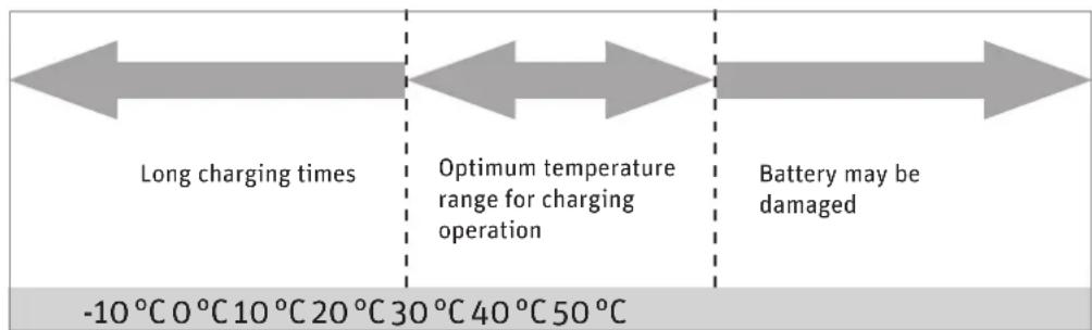
flowchart
graph LR
    A["Long charging times"] --> B["Optimum temperature range for charging operation"]
    B --> C["Battery may be damaged"]
    D["-10°C 0°C 10°C 20°C 30°C 40°C 50°C"] --> A
    E["-10°C 0°C 10°C 20°C 30°C 40°C 50°C"] --> B
Charging times at different temperatures
7.4 Battery information system
There is a display panel on the outer face of the battery which includes five LEDs and a button with an LED (Push). When you press the Push button, the LEDs light up. Information about the battery and its charge state is provided based on the number of LEDs that light up and the way in which they light up.

Charge state and battery capacity indicator
7.4.1 Checking the battery charge state
Press the Push button briefly; the LEDs light up and display the current battery charge state.
| DISPLAY BATTERY CHARGE STATE | |
| ...... | 5 LEDs light up 100 – 84% |
| ...... | 4 LEDs light up 83 – 68% |
| ... | 3 LEDs light up 67 – 51% |
| .. | 2 LEDs light up 50 – 34% |
| • | 1 LED lights up 33 – 17% |
| ○ | 1 LED flashes 16 – 0% |
| ○○○○ | 5 LEDs flash quickly 0% or overloaded * |
| • | 1. LED flashes quickly Charging fault ** |
* All 5 LEDs flash quickly: The battery is empty and is being switched off, or is overloaded.
If the battery is overloaded, it will switch back on after a short idle period and can then be used normally.
If the battery is empty, it will work once again briefly following a short period of rejuvenation and will then switch back off. It must now be charged.
** The 1st LED flashes quickly: A charging fault is present.
If this occurs, put the battery in the docking station for a short period of time or insert the plug of the charger into the battery. The charger performs a readjustment. If the LED still flashes, take the battery to your specialist cycle shop and have it checked.
7.4.2 Checking the battery capacity
If you press the "Push" button for five seconds, the LEDs show the current capacity of the battery.
| DISPLAY | CAPACITY | |
| ...... | 5 LEDs light up | 100 – 97% |
| ...... | 4 LEDs light up | 96 – 80% |
| ... | 3 LEDs light up | 79 – 60% |
| .. | 2 LEDs light up | 59 – 40% |
| • | 1 LED lights up | 39 – 20% |
| ○ | 1 LED flashes | < 20% |
The range of the battery is less in winter due to the lower temperatures. Only move the battery (from the warm room where you store it) and fit it on your Pedelec just before you set off. This will help to prevent the effect of the low temperature on the range of the battery. Chapter 7.5.2 “Service life and warranty of the battery”
7.5 Service life and warranty
7.5.1 of the drive
The Impulse centre motor is a durable maintenance-free drive. It is a wear part with a two-year warranty. As its power output is higher, wear parts such as the drive and brakes are subject to higher loads than they would be on a normal bike. Due to the greater force acting on these components, wear is more pronounced.
7.5.2 of the battery
Batteries are wear parts. Wear parts come with a two-year warranty.
If the battery develops a fault during this period, your specialist cycle shop will of course replace it. Normal ageing and battery wear do not constitute a fault.
The service life of the battery depends on different factors. The most important wear-relevant factors are
• the number of charging processes
After 1,100 charging cycles, your battery will still have 60% of its initial capacity, providing it has been well looked after. This means 6.6 Ah in an 11 Ah battery and 7.2 Ah in a 15 Ah battery. A charging cycle is defined as the sum of the individual charges until the charges reach the overall capacity of the battery.
For example: You charge the battery with 5 Ah on the first day, 2 Ah on the second day and 4 Ah on the third day; the sum is 11 Ah. The battery has thereby completed one charge cycle.
From the technical standpoint therefore, the battery is exhausted at this point. Providing you can still cover the journey distances with the remaining battery capacity, you can of course continue using it. If the capacity is no longer sufficient, you can take your battery to a specialist cycle shop who will dispose of your battery and sell you a new one.
• the age of the battery.
A battery also ages during storage.
A lithium-nickel-cobalt-manganese battery loses approx. 4-5% of its initial capacity per year and a lithium-nickel-cobalt-aluminium-oxygen battery approx 2-3%.
This means: Even if you do not use your battery, its capacity reduces. With everyday use, you can expect the battery to age by approximately 3-5% per year as a result of ageing and charging processes.
- You can extend the service life of the battery by fully recharging it after every journey, however short. The Impulse Li-ion battery has no memory effect.
- You can also extend the service life of the battery by using the assistance selectively.
8 Charger
Read the two type plates on the charger before using it for the first time.
You can charge your Pedelec with Impulse drive directly via a charging socket in the battery. The battery can remain on the Pedelec when the charging operation is in progress.

natural_image
Black-and-white photo of a bicycle with attached rear panel and charging cable, no visible text or symbolsYou can also take the battery out of the holder and charge it in the docking station. This is recommended if it is cold outside, in order to charge the battery in a warm room.

natural_image
Two electronic devices with wires, one connected to a black rectangular base and the other a black vertical stand (no visible text or symbols)Battery in the docking station

Do not use other chargers. Only charge the battery using the charger provided, or a charger approved by us.
If a charging fault occurs, the LED in the charger flashes red. In this case, the charging current is too high.

Take the battery out of the charger, then put it back in again.
If the error message appears again, the battery and charger must be checked by a specialist dealer.
If used incorrectly, the device may be damaged or inflict injuries.
Before cleaning the charger, always pull the plug out of the socket to avoid a short-circuit and/or physical injury.
Only use the charger in dry rooms.
Only place the charger in a secure stable position on a suitable surface.
Do not cover the charger or place any objects on it as otherwise it could overheat and catch fire.
9 Cleaning

Remove the battery before you clean your Pedelec.
We recommend you clean your Pedelec with a damp cloth, a sponge or a brush. You can obtain suitable cleaning agents and additional information from your specialist cycle shop.
Make sure when cleaning that water does not enter the battery. Although the electrical components are sealed, it is not advisable to clean the bike by spraying it with a hose or a high-pressure cleaner. This could damage your bike.
When wiping down the battery, be careful not to touch and connect the contacts on the underside. This could cause the battery to switch off.
10 Warnings

Bear in mind that the Pedelec motor can heat up on long ascents. Be careful not to touch it with your hands, feet or legs. You could burn yourself.
If you are transporting your Pedelec by car, remove the battery beforehand. Transport the battery in a safe receptacle separately to the Pedelec.
The Pedelec operates using low voltage (36 volts). Never attempt to operate the Pedelec using power from a source other than a suitable genuine battery. The designations of approved batteries are listed in Chapter 11 "Technical data".
Live parts may be exposed when you open covers or remove parts. Connection points may also be live. Maintenance or repairs on the device when it is open and connected to the power supply must only be carried out by the specialist cycle shop.
When carrying out adjustments and maintenance or when cleaning the Pedelec, avoid crushing cables or damaging them with sharp edges.
If risk-free operation of your Pedelec cannot be assumed, take it out of operation and make sure it cannot be used until you have it checked by a specialist cycle shop. Risk-free operation is no longer possible if live parts or the rechargeable battery show signs of damage.
Keep children away from electrical appliances. If children are present, keep a close eye on them, especially if there is a possibility they could insert objects into the appliance through apertures in the housing. This poses the danger of fatal electric shock.
When charging the battery, make absolutely sure the charger is correctly supported on its four feet. It must not be covered when in operation. It must be possible for the heat produced to dissipate via the surrounding ventilation slots on the top and bottom.
11 Technicaldata
MOTOR
Brushless electric motor with gear unit and freewheel
Output 250 watts
Maximum torque 40 Nm at chainring
| Gross weight of electric drive, battery, control unit | Freewheel motor | Back-pedal motor | ||
| 11 Ah | 15 Ah | 11 Ah | 15 Ah | |
| 6.65 kg | 6.75 kg | 6.75 kg | 6.8 kg | |
Control via torque sensor and rota- tional speed sensor in motor and speed sensor (on rear wheel)
IMPULSE LI-ION BATTERY
Capacities 11 Ah 15 Ah
Voltage 36 V 36 V
Weight 2.85 kg 2.95 kg
We hope you thoroughly enjoy using your new Pedelec with Impulse drive.
Copyright © 2012 Raleigh Univega GmbH
Reproduction, in whole or in part, is not permitted without the consent of Raleigh Univega GmbH. Subject to misprints, errors and technical modifications.
VI
User Manual Groove Pedelec
English
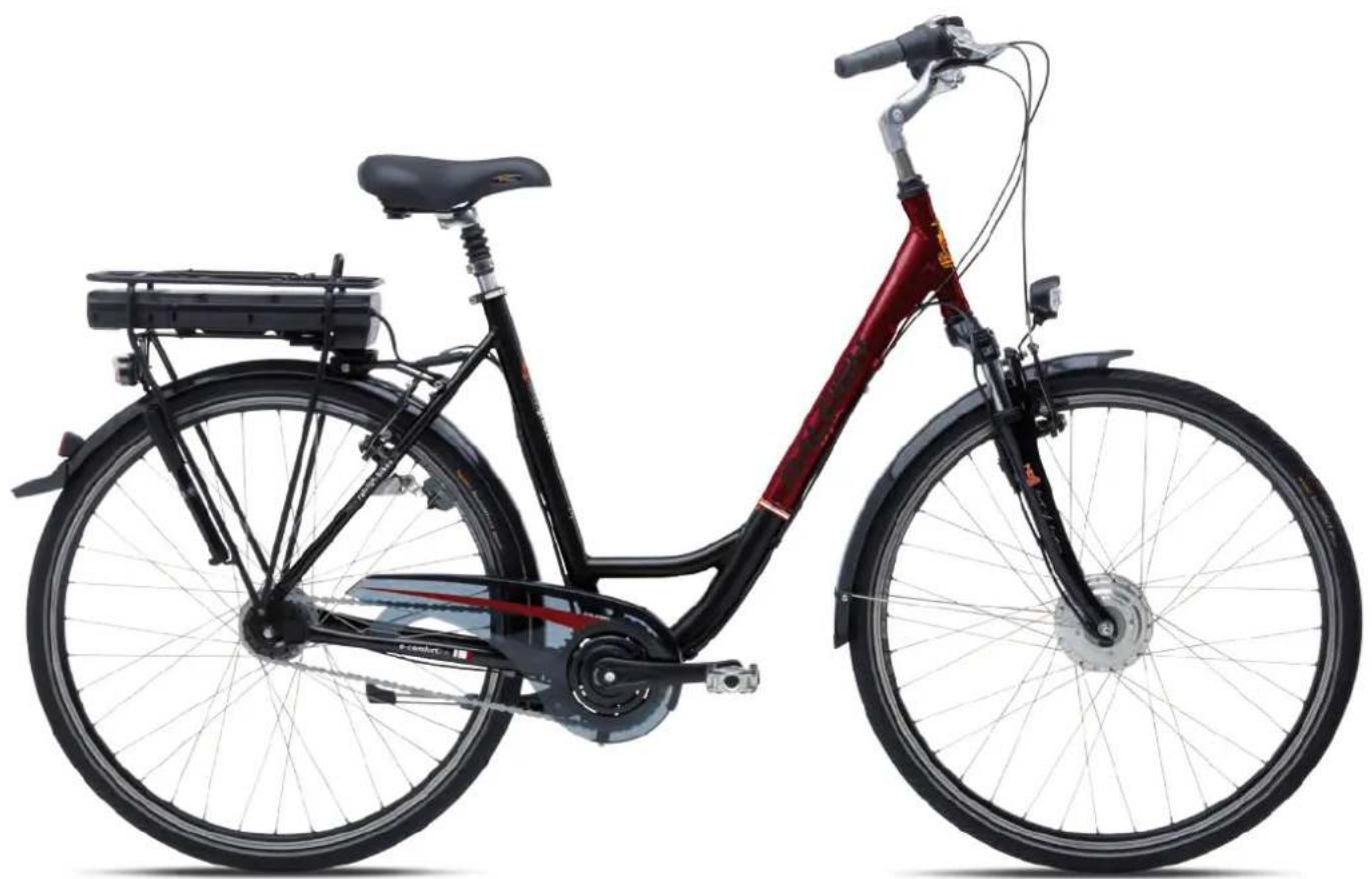
natural_image
Side view of a black and red bicycle with dual-panel roof, showing front wheel, rear wheel, and side panel (no text or symbols visible)
natural_image
Exterior view of a battery pack and charging device with labeled components (no text or symbols visible)Battery and charger

natural_image
Mechanical assembly diagram showing a bracket with labeled parts (no readable text or symbols)Battery lock
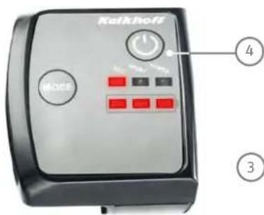
Control panel

natural_image
Close-up of a bicycle wheel assembly with visible stator and rotor blades (no text or symbols)Motor unit

Dear Customer,
Thank you for choosing a Pedelec (pedal electric cycle) featuring the innovative Groove drive from our company. This bike is equipped with an electric drive that assists you when you are cycling. This will make your trip much more enjoyable if you are riding up hills, carrying loads or riding into the wind. You can decide yourself how much you want to use it. The purpose of this User Manual is to help you get the most out of your Pedelec and use it correctly.
Structure of User Manual
If you want to get started right away, refer to the brief introduction in ➔ Chapter 1 "Quick start".
The individual steps are subsequently explained in detail, supplemented by illustrations and diagrams.
More detailed information on your Pedelec is provided in Chapter 12 "Technical data".
The information in this User Manual specifically refers to your Pedelec only. For general information, on the bike technology that features in your Pedelec for example, refer to the General User Manual.

Even if you can't wait to go for your first ride, in the interest of your own safety you should read Chapter 1 "Quick start" carefully without fail before use.
In addition to texts and tables, the User Manual contains the following symbols that denote important information or dangers.
WARNING about possible physical injury, increased risk of falls or other injuries

IMPORTANT ADDITIONAL INFORMATION or special information on using the bike

NOTE about possible damage to property or the environment
Contents
EC Declaration of Conformity
2012
20136
1 Quick start 7
2 Legal principles 8
2.1 Meaning for the rider 8
2.2 Pushing assistance 8
3 Special features of Pedelec with Groove drive 8
4 Charging the battery 9

4.1 Charging operation
4.2 Fitting the battery
5 Control panel
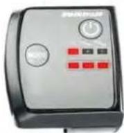
5.1 On/Off button
5.2 Switches for power-assist level
5.3 Display of power-assist mode
5.4 Battery charge state indicator
5
6 Assistance by the electric motor 13

natural_image
Close-up of a bicycle wheel assembly with visible stator and rotor blades (no text or symbols)6.1 Operating principle of assistance 13
6.2 Distance 13
6.3 Riding your Pedelec efficiently 14
7 Battery 14
7.1 Straightforward charging 14
7.2 High degree of safety due to battery management 14
7.3 Straightforward storage 14
7.4 Battery information system 15
7.5 Battery charge state 15
7.6 Service life and warranty 16
7.6.1 of the drive 16
7.6.2 of the battery 16
8 Charger 16

natural_image
Exterior view of a black rectangular electronic device with a small power adapter connected to its side, no visible text or symbols.9 Removing the front wheel 17
10 Cleaning 18
11 Warnings 18
12 Technical data 19
EC Declaration of Conformity 2012 CE
The manufacturer: Raleigh Univega GmbH
Siemensstraße 1–3
49661 Cloppenburg, Germany
Telephone: +49 (0) 4471/9234-0
hereby declares that the following products:
Product description: Raleigh Pedelec Panasonic
Model designation:
Dover de Luxe 7G, Dover de Luxe 8G, Dover 3G, Dover Premium 8G, Leeds Sport 11G, Leeds HS 8G, Leeds Roller, Leeds Tour 7G, Stoker Lite Premium, Stoker 360, Stoker Lite 8G, Stoker DD, Dover LTD, Dover XXL LTD
Product description: Raleigh Impulse
Model designation:
Dover 125th Impulse, Dover Premium Impulse, Dover XXL Impulse, Dover HS Impulse, Impulse XXL, Impulse, Impulse HS, Impulse Compact, Leeds Compact, Dover Impulse
Product description: Raleigh Groove
Model designation:
Groove F3, Groove F8
Product description: Raleigh BionX
Model designation:
Blackburn 7, Blackburn 5, Blackburn 3
Product description:
Raleigh Bosch Pedelec
Model designation:StokerB
Year of manufacture:
2012
comply with all of the relevant requirements of the Machinery Directive (2006/42/EC).
Furthermore, the machine complies with all of the requirements of the Electromagnetic Compatibility Directive (2004/108/EC).
The following harmonized standards have been applied:
DIN EN 15194 Cycles – Electrically power-assisted cycles – EPAC cycles
DIN EN 14764
City and trekking bikes – Safety requirements and test methods
Technical documentation filed at:
49661 Cloppenburg, Germany

Olaf Flunkert
Production, Purchasing and
Technology Manager
M. K. Chen Hoge
Karl-Heinz Lange
Design and Development Manager
49661 Cloppenburg, Germany
21.09.2011
EC Declaration of Conformity 2013 CE
The manufacturer: Raleigh Univega GmbH
Siemensstraße 1–3
49661 Cloppenburg, Germany
Telephone: +49 (0) 44 71 / 92 34 - 111
hereby declares that the following products:
Product description: Raleigh Pedelec Panasonic
Model designation: Dover de Luxe P8 36V, Dover de Luxe P8R 36V, Dover de Luxe P8 26V, Dover de Luxe 8G 26V, Dover de Luxe 7G 26V, Dover de Luxe 2x8 8G, Leeds Sport
Product description: Raleigh Impulse Pedelec
Model designation: Impulse iR, Impulse iR HS, Impulse iR Classic, Impulse iR Premium, Impulse iR XXL, Impulse iR Compact, Stocker i11 Di2, Stocker i Light Premium, Stocker iR Light, Stocker IDD, Leeds i Light, Leeds i HS, Leeds iR HS, Leeds i Roller, Leeds iR Tour, Leeds I Compact, Dundee iR Cargo, Dundee i Compact, Dover i, Dover I HS, Dover i XXL, Dover i Premium, Dover i360, Dover i360 Harmony
Product description: Raleigh Groove Pedelec
Model designation: GrooveF8
Product description: Raleigh Xion Pedelec
Model designation: Blackburn 5, Blackburn 3
Product description: Raleigh Bosch Pedelec
Model designation: Stoker B8, Stoker B9
Year of manufacture: 2013
comply with all of the relevant requirements of the Machinery Directive (2006/42/EC).
Furthermore, the machine complies with all of the requirements of the
Electromagnetic Compatibility Directive (2004/108/EC).
The following harmonized standards have been applied:
DIN EN 15194 Cycles – Electrically power-assisted cycles – EPAC cycles
DIN EN 14764 City and trekking bikes – Safety requirements and test methods
Technical documentation filed at:
49661 Cloppenburg, Germany

Olaf Flunkert
Production, Purchasing and
Technology Manager
Mard-Heni Hoge
Karl-Heinz Lange
Design and Development Manager
49661 Cloppenburg, Germany
14.05.2012
1 Quickstart
- Charge the battery completely before riding for the first time.
- Open the round charging socket cover on the back of the battery.

natural_image
Close-up of a mechanical component with a circular base and flange, no visible text or symbolsCharging socket
Now insert the plug of the charger into the battery charging socket.
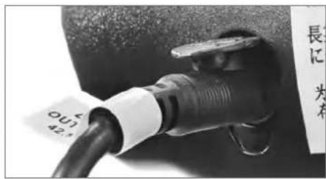
Charging the battery
- Insert the mains plug for the charger into the socket.
You must fully charge the battery before using it for the first time.
- The battery is fully charged if all green LEDs on the back of the battery light up when you press the adjacent button.
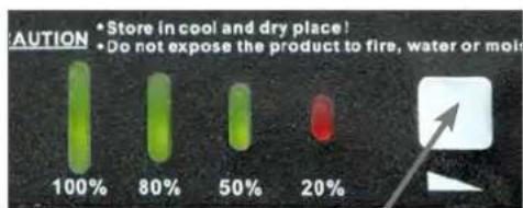
Button on the battery
Pull the charger plug out of the battery socket. Close the charging socket cover
You can also remove the battery from your Pedelec and charge it somewhere else. For more information, refer to ➞ Chapter 4 "Charging the battery".
-
If you have charged the battery somewhere other than on the Pedelec, place the battery back into the holder in the pannier rack by reinserting it from behind. Once you have inserted the battery, turn the key clockwise and then remove it, otherwise the battery will not lock into position.
-
Make sure that the battery is securely positioned and that the key is no longer in the lock.
-
Press the round switch on the side of the battery housing. The red LED inside it lights up.
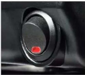
natural_image
Close-up of a black circular button with a red indicator light on the left side (no text or symbols visible)Switch, battery housing
-
Push the POWER button on the control panel on the handlebar.
-
The display panel now displays the medium power-assist mode SPORT. Press the Mode button to select the level of assistance: ECO (low), SPORT (medium) or POWER (high). Press this button once to change the level of assistance by one level. Once the POWER assist level has been activated, the assistance jumps back to ECO the next time the button is pressed.

You can ride off just as you would if you were riding a normal bike. The power assist starts after roughly two complete crank revolutions.
- You can now ride off.
2 Legalprinciples
The essential idea behind the Pedelec is not only to be able to cover greater distances more quickly, but also more comfortably. You can choose to relax and let the bike do the work, exert yourself more physically, or simply get from A to B as fast as possible. You can decide this yourself by choosing an appropriate assist level.
This gives you more confidence on the road, as the powerful acceleration gives you more control and a greater degree of security. Your Pedelec provides you with power assistance, the level of which you can vary at the control panel.
In some EU countries, the Pedelec, like all other bikes, must comply with certain regulations, the Road Traffic Licensing Regulations (StVZO) in Germany for example. Please observe the relevant explanations and general information provided in the General User Manual.
These statutory requirements apply for a Pedelec:
- The motor is designed only to provide pedalling assistance, i.e. it can only "assist" the rider when he/she turns the pedals.
• The average motor output must not exceed 250 W. - As the speed increases, the rate at which the motor output reduces must also increase more intensely.
- The motor must switch off once the bike reaches a speed of 25 km/h.
2.1 Meaning for the rider
- You do not legally have to wear a helmet. In the interest of your own safety, however, you should never ride without a helmet.
- You do not legally have to have a driving license (unless you own a model with pushing assistance, Chapter 2.2 "Pushing assistance").
- You do not legally have to have insurance.
• No age restriction applies for a Pedelec. - The regulations governing the use of cycle paths are the same as for normal bikes.
These regulations apply to you wherever you are in the European Union. It is possible that different regulations exist in other countries, also inside the EU in individual cases. Before using your Pedelec abroad, find out about the legal situation in the relevant country.
2.2 Pushingassistance
Your Pedelec is available in a version with or without pushing assistance.

natural_image
Close-up of a mechanical device with a circular logo and lever mechanism (no visible text or symbols)Button for pushing assistance
The pushing assistance moves the Pedelec slowly (at a maximum speed of 6 km/h) without you having to turn the pedals, e.g. if you are manoeuvring in a tight space or are pushing your Pedelec out of a basement garage.
If you were born after 01. 04. 1965, you will need a moped test certificate for the version with pushing assistance. If you already have another type of driving licence, this automatically includes the moped test certificate.
The pushing assistance is not suitable for use as starting assistance.
3 Special features of Pedelec with Groove drive
Your Pedelec is equipped with special features that are designed to enhance your safety and comfort.
With the Groove drive, you can ride your Pedelec, and also benefit from the convenience and safety of a back-pedal function.
This means that you can rely on three brakes; the familiar back-pedal brake and the powerful, modern rim brakes.

1 Rim brake, front
2 Back-pedal brake
3 Rim brake, rear
The Groove drive also makes it possible to ride with power assistance even if you are only gently turning the cranks.

If you decide to use the power assistance when only gently turning the cranks, you will use a much greater amount of power than if you were actively pedalling at the same time.
4 Charging the battery
You can charge the battery whilst it is on the Pe-delec (as described in ➞ Chapter 1 "Quick start").

natural_image
Side view of a bicycle with attached charging station and cable, shown against plain background (no text or symbols visible)You can also remove the battery from the holder and charge it in the docking station. This is recommended if it is cold outside, in order to charge the battery in a warm room.

Hold the battery by the recessed grip at the back of the battery and turn the key anticlockwise.
This unlocks the battery and you can now remove it by pulling it backwards out of the Pedelec. In doing so, hold on tight to the battery to prevent it from being dropped.
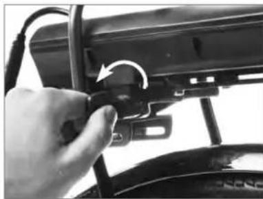
natural_image
Close-up of a hand adjusting a black mechanical component with a circular arrow indicating rotation (no text or symbols visible)Unlocking the battery

natural_image
Close-up of a hand holding a black mechanical device with a circular button, no visible text or symbolsRemoving the battery
You should now remove the key and keep it in a safe place to prevent it from breaking off or being lost.
4.1 Chargingoperation
Before charging the battery, read the directions on the charger carefully.
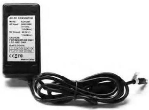
Sticker on the underside of the charger
- Take the charger provided out of its packaging and plug the mains plug into a socket (230 V, please observe type plate on the charger).
To charge the battery safely, the charger must be placed on a suitable surface resting on its four feet with the LED facing upwards.
- The LED in the charger now lights up green.
- Insert the plug of the charger into the battery charging socket. The battery and charger are connected.
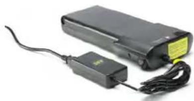
natural_image
Black electronic device with attached power adapter and cable, no visible text or symbolsBattery with charging cable plugged in
- The charging process starts.
The LED in the charger now lights up red. You can check the battery's charge state by pressing the square button on the battery to the right of the LEDs. The greater the number of LEDs that light up the higher the charge state is.

LEDs on the battery
- If the LED on the charger lights up green, the battery is fully charged.
- To save power, pull the charger plug out of the socket once the charging operation is complete. You can also leave the charging cable plugged in once the charging operation is complete. However, the charger always draws some current if you leave it plugged in.
4.2 Fitting the battery
- Push the battery into the rear of the battery housing under the pannier rack. To do this, the battery key must be inserted and turned clockwise.

natural_image
Close-up of a hand holding a black electronic device with a scroll wheel, showing mechanical components and a directional arrow (no text or symbols visible)Reinstalling the battery
- Push the battery fully into the battery housing. Now turn the key anticlockwise and then remove it to lock the battery.
- Make sure the battery is firmly in place.
- Push down the round rocker switch on the left-hand side of the battery housing. A red LED lights up.
- The Pedelec is now ready for operation.
5 Control panel

1 Button for power assist level
2 On/Off switch
3 Power-assist mode display
4 Battery charge state indicator
The control panel on the handlebar has two or three buttons (depending on the model) and two rows of LED indicators. The button used to control the level of assistance is located on the left-hand side of the control panel.
To the right at the bottom you can see the LED display bar which indicates the level of assistance which has been activated and the current battery charge state.
The POWER button is located above the LEDs.
Press this button to switch the control panel on and off.
natural_image
Simple circular icon with a white power button symbol (no text or numbers)On/Off button
If the model features pushing assistance, the switch for this will be on the underside of the control panel.

natural_image
Close-up of a camera lens and camera module with a bicycle logo on the handle (no readable text or symbols)Button for pushing assistance
5.1 On/Off button
Press the POWER button to switch the control panel on and off.
After it has been switched on, the system is always in the medium power-assist mode SPORT.
5.2 Switches for power-assist level
You can specify the power assist level via the Mode button.
Buttons for power assist level
Each time you press the Mode button the power assist changes by one level.
Each time you press the Mode button, the assistance changes by one level from ECO through to the highest level POWER.
If you require less assistance, press the Mode button until the level of assistance moves from the highest back to the lowest level.
5.3 Display of power-assist mode
The upper row of LED indicators on the right next to the Mode button shows how much assistance the motor is currently providing.
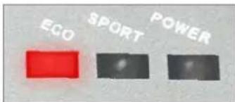
Display of power-assist mode
DISPLAY ASSIST LEVEL
| POWER | ||
| SPORT | ||
| ECO | ||
Assist level
- The LED on the right of the display lights up when the highest level of assistance (POWER) is activated. This means the assistance is working hard.
- The LED in the centre of the display lights up when the medium assist level (SPORT) is activated. This means the assistance is working with a medium level of effort.
- The LED on the left of the display lights up when the lowest level (ECO) is activated and the assistance is working only with a low level of effort.
5.4 Battery charge state indicator
The battery charge state indicator is located below the row of LED indicators that displays the power-assist mode.

natural_image
Three red rectangular blocks arranged horizontally on a white background (no text or symbols)Battery charge state indicator
- If all three battery charge state indicator LEDs are lit, the battery charge is between 100 and 65% .
- If two LEDs are lit, the battery charge is still between 65 and 35% .
- If only one LED is lit, the battery charge is between only 35 and 10%.
- If only one LED is flashing, the battery charge is less than 10%. At this point you will notice a slight loss of power.
- If the battery charge state falls below a minimum level, the system switches off. No LEDs light up on the control panel.
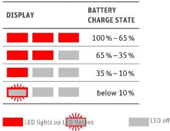
bar
| DISPLAY | BATTERY CHARGE STATE (%) | | :--- | :--- | | 100% - 65% | 100% - 65% | | 65% - 35% | 65% - 35% | | 35% - 10% | 35% - 10% | | below 10% | below 10% |Battery charge state
6 Assistance by the electric motor
6.1 Operating principle of assistance
If you switch on the assistance and start pedalling, the motor starts up once the cranks have completed roughly two complete revolutions.
The amount of propulsion provided by the motor depends on which level of assistance you have selected.
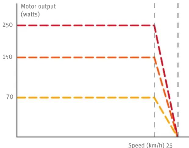
line
| Speed (km/h) | Motor output (watts) | | ------------ | -------------------- | | 0 | 250 | | 1 | 250 | | 2 | 250 | | 3 | 250 | | 4 | 250 | | 5 | 250 | | 6 | 250 | | 7 | 250 | | 8 | 250 | | 9 | 250 | | 10 | 250 | | 11 | 250 | | 12 | 250 | | 13 | 250 | | 14 | 250 | | 15 | 250 | | 16 | 250 | | 17 | 250 | | 18 | 250 | | 19 | 250 | | 20 | 250 | | 21 | 250 | | 22 | 250 | | 23 | 250 | | 24 | 250 | | 25 | 250 |The motor can operate with three different power output levels.
- The motor delivers a continuous output of 70 watts at the lowest level ECO, 150 watts at the medium level SPORT, and 250 watts at the highest level POWER.
- When the switch is in the POWER position, the motor assists you with the highest output and therefore also uses the most energy. If you select the SPORT assist level, the motor output is slightly lower. If you select ECO, you will receive the lowest level of assistance but will be able to use the maximum range of the battery.
- The motor provides assistance until the Pedelec reaches a speed of 25 km/h. It then switches off.
6.2 Distance
The distance you can travel using the power assist with the battery fully charged depends on several factors:
- Ambient temperature
If it is colder, you will travel a shorter distance with the same battery charge.
To maximise the distance you can travel, keep the battery in a heated room so that it is at room temperature when you fit it on your Pedelec.
As the battery discharges when the motor is in use, it generates enough heat to not lose too much of its power at low ambient temperatures.
• Level of assistance selected
If you wish to ride a long distance assisted by the motor, select a low level of assistance (ECO).
- Riding approach
You can ride assisted almost entirely by the motor by turning the pedals very gently. However, this uses more battery power. You can save power by putting in more effort when turning the pedals.
• Technical condition of your Pedelec
Make sure that the tyre pressure is correct. If you ride your bike with too little air in the tyres, this can significantly increase the rolling resistance. This applies to smooth surfaces in particular, e. g. tarmac. If the ground is uneven, as on a country path or gravel track, rather low tyre pressure can lead to less rolling resistance. This also increases the risk of a puncture. Please consult your specialist dealer about this.
The distance you can travel also decreases if the brakes are rubbing.
- Topography
The motor uses more power when riding in hilly rather than flat terrain.
6.3 Riding your Pedelec efficiently
You can monitor and influence the cost of your journeys with the Pedelec yourself. You can reduce your consumption and therefore costs by following the tips for achieving a long range.
The operating costs for battery-operated power assist are calculated as follows:
• A new battery costs roughly 359 euros.
- You can cover 45 km on average with one battery charge.
- You can charge the battery roughly 1,100 times.
• 1,100 charging cycles x 45 km = 49,500 km
• 359 euros: 49,500 km = 0.7 euro cents / km
- You use roughly 0.47 kWh to fully charge the battery. Assuming a unit price of 20 euro cents / kWh, it costs you 9.4 euro cents to fully charge the battery.
- It costs you 0.2 euro cents / km to cover the average range of 45 km.
- This means that the maximum cost of consumption and the battery is 0.9 euro cents/km.
The sample calculation has been carried out based on German energy prices. The operating costs may therefore be different in locations where other energy prices apply.
7 Battery
Your battery is a lithium cobalt battery, the ideal lithium-ion (Li-Ion) battery type for this application. One of the main benefits of this type of battery is its low weight combined with a high capacity. Li-Ion batteries only weigh half as much as comparable nickel metal hydride or nickel-cadmium batteries. This means you carry less battery weight and more battery power.
7.1 Straightforwardcharging
There is no memory effect. You can therefore fully recharge your battery after every trip.
Recharge the battery after every trip. This means you can set off immediately the next time you use your bike and you also increase the service life of the battery.
If you are not using the battery, you only have to recharge it after 6 months.
7.2 High degree of safety due to battery management
The battery cannot be damaged as a result of a short-circuit. If this were to happen, the battery management would switch off the battery.
You can simply leave the battery standing in the charger as the device has in-built overcharging protection.
7.3 Straightforwardstorage
If you do not need your battery for a while, store it at a temperature of +10°C when the battery charge is between 50 and 75%.
These benefits are available due to highly effective battery management that has been adapted to this specific application and by tuning the battery for operation with a 250 watt motor.

Observe the following points to increase the service life of your Pedelec battery:
Make sure that the battery is fully charged before you ride your bike for the first time or if you have not used it for a while.
You should run the battery all the way down to empty for the first three charging cycles. This allows the battery to reach its maximum capacity.
If you continuously run the battery to empty during normal operation, this reduces its service life.
If you partially recharge the battery frequently during normal operation, this has a favourable effect on its service life.
You should therefore partially recharge the battery whenever possible: Try not to run the battery all the way down to empty and recharge it even after short periods of operation.
If you are having problems with the battery, place it in the charger for one minute. This resets the battery. After this, the battery will work again.
Ideally you should charge the battery at a temperature of between +10°C and +30°C. It takes longer to charge the battery at low temperatures, the battery will not charge up at temperatures higher than +30°C. Ideally, you should charge and store the battery inside your house or in a warm garage when the outside temperature is low. In this case you should only fit the battery on your bike just before using it.
If you are transporting your Pedelec by car, take the battery out of its holder and transport it separately.
The battery should ideally be stored for longer periods with a charge of between 50% and 75% at a temperature of +10°C.
7.4 Battery information system
There is a display panel on the top of the battery which contains four LEDs and a button. The LEDs light up if you press the button. Information about the battery and its charge state is provided based on the number of LEDs that light up and the way in which they light up.
7.5 Battery charge state
Press the switch on the battery briefly to activate the LEDs and see the current battery charge state.

Charge state indicator
DISPLAY BATTERY CHARGE STATE
| ····· | 4 LEDs light up 100–75% | |
| ··· | 3 LEDs light up | 75–50% |
| ··· | 2 LEDs light up | 50–25% |
| • | 1 LED lights up | 25–0% |
If the battery is empty, it will work once again briefly following a short period of rejuvenation and will then switch back off. It must now be charged.
Check the battery charge before every trip to make sure it is sufficient for the planned journey.

Charging times at different temperatures
The range of the battery is less in winter due to the lower temperatures. Only move the battery from the warm room where you store it and fit it on your Pedelec just before you set off. This will help reduce the effect of the low temperature on the range of the battery.
The distance you can cover can vary depending on the topography, the condition of the battery and the assist level you are using.
7.6 Service life and warranty
7.6.1 of the drive
The Groove hub motor is a durable maintenance-free drive. It is a wear part with a two-year warranty. As its power output is higher, wear parts such as the tyres and brakes are subject to higher loads than they would be on a normal bike. Due to the greater force acting on these components, wear is more pronounced.
7.6.2 of the battery
Batteries are wear parts. Wear parts come with a two-year warranty.
If the battery develops a fault during this period, your specialist cycle shop will of course replace it. Normal ageing and battery wear do not constitute a fault.
The service life of the battery depends on different factors. The most important wear-relevant factors are
• the number of charging cycles and
• the age of the battery.
According to the technical definition, the battery is used if its capacity is only 60% in the new condition.
The battery of course also ages over time. Even if you do not use your battery, its capacity reduces. In general, the battery is expected to age at a rate of 5% per year.
Providing you can still cover the journey distances with the remaining battery capacity, you can of course continue using it. If the capacity is no longer sufficient, you can take your battery to a specialist cycle shop who will dispose of your battery and sell you a new one.
You can extend the service life of the battery by fully recharging it after every journey, however short. The Groove Li-Ion battery has no memory effect.
You can also extend the service life of the battery by using the assist levels selectively. Avoid riding with a high assist level when you are only gently turning the pedals.
8 Charger
Read the two identification plates on the charger before using it for the first time.
You can charge your Pedelec with Groove drive directly by connecting the plug of the charger to the battery.

Charging the battery
The battery can remain on the Pedelec during the charging process.
You can also remove the battery from the holder on the Pedelec and charge it somewhere else. This recommended if it is cold outside, in order to charge the battery in a warm room.
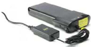
natural_image
Black electronic device with attached power adapter and cable, no visible text or symbolsBattery with charging cable plugged in

Do not use other chargers. Only charge the battery using the charger provided, or a charger approved by us.
If a problem occurs, remove the battery from the Pe-delec and place it briefly in the charger. The charger tests the battery and corrects any faults that may be present.

If used incorrectly, the device may be damaged or inflict injuries.
Before cleaning the charger, always pull the plug out of the socket to avoid a short-circuit and/or physical injury.
Only use the charger in dry rooms.
Only place the charger in an upright, secure and stable position on a suitable surface.
Do not cover the charger or place any objects on it as otherwise it could overheat and catch fire.
9 Removing the front wheel
If you need to remove the front wheel, to repair a puncture for example, this can be done in the same way as removing the front wheel of a normal bike, excluding one procedure.
The first thing you must do before releasing the front wheel is to open the connection to the front wheel motor.
Undo the locking nut for the electrical connector which is located on the back of the fork. Take the upper half of the connector in one hand and the lower half in the other and pull the two halves apart.
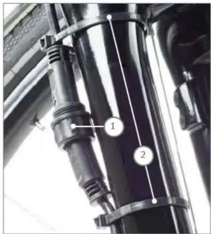
1 Locking nut 2 Cable tie
The lower half of the connector and the power cable are fastened to the fork with two cable ties.
Slide the cable ties down and off the fork. You can now remove the front wheel. You can find corresponding instructions in the section of this User Manual that deals with general bike technology. If you take the front wheel out of the fork, also pull the cable and cable tie off the fork.
To reinstall the front wheel, slide the cable tie with cable onto the fork leg before positioning the wheel in the fork. Install the front wheel as described in the general section of this User Manual.
Next, reattach the two halves of the connector and screw the lock nut firmly back on. Slide the two cable ties back up the fork until they remain in place of their own accord and cannot slip.
10 Cleaning

Remove the battery before you clean your Pedelec.
We recommend you clean your Pedelec with a damp cloth, a sponge or a brush. You can obtain suitable cleaning agents and additional information from your specialist cycle shop.
Make sure when cleaning that water does not enter the battery. Although the electrical components are sealed, it is not advisable to clean the bike by spraying it with a hose or a high-pressure cleaner. This could damage your bike.
When wiping down the battery, be careful not to touch and connect the contacts on the underside. This could cause the battery to switch off.
If risk free operation of your Pedelec cannot be assumed, take it out of operation and make sure it cannot be used until you have it checked by a specialist cycle shop. Risk-free operation is no longer possible if live parts or the rechargeable battery show signs of damage.
Keep children away from electrical appliances. If children are present, keep a close eye on them, especially if there is a possibility they could insert objects into the appliance through apertures in the housing. This poses the danger of fatal electric shock.
When charging the battery, make absolutely sure the charger is correctly supported on its four feet. It must not be covered when in operation. The heat produced by the battery must be able to dissipate.
Always engage the brake if you are at a traffic light. If you move the pedals by accident, this could start up the motor and cause the bike to set off.
11 Warnings

Bear in mind that the Pedelec motor can heat up on long ascents. Be careful not to touch it with your hands, feet or legs. You could burn yourself.
If you are transporting your Pedelec by car, remove the battery beforehand. Transport the battery in a safe receptacle, separately to the Pedelec.
The Pedelec operates using low voltage (36 volts). Never attempt to operate the Pedelec using power from a source other than a suitable genuine battery.
Live parts may be exposed when you open covers or remove parts. Connection points may also be live. Maintenance or repairs on the device when it is open and connected to the power supply must only be carried out by the specialist cycle shop.
When carrying out adjustments and maintenance or when cleaning the Pedelec, avoid crushing cables or damaging them with sharp edges.
12 Technicaldata
MOTOR
Brushless electric motor with planetary gear unit and freewheel
Output 250 watts
Maximum torque 35 Nm
Weight of motor 2.88 kg
Assist levels 70, 150, 250 watts
Switch-off speed 25 km/h at all assist levels
Control via speed sensor
We hope you thoroughly enjoy using your new Pedelec with Groove drive.
Copyright © 2012 Raleigh Univega GmbH
Reproduction in whole or in part is not permitted without the consent of Raleigh Univega GmbH. Subject to misprints, errors and technical modifications.
DERBY CYCLE
powered by
BionX™
BionX
User Manual
EC Declaration of Conformity 2012 CE
The manufacturer: Raleigh Univega GmbH
Siemensstraße 1–3
49661 Cloppenburg, Germany
Telephone: +49 (0) 4471/9234-0
hereby declares that the following products:
Product description: Raleigh Pedelec Panasonic
Model designation:
Dover de Luxe 7G, Dover de Luxe 8G, Dover 3G, Dover Premium 8G, Leeds Sport 11G, Leeds HS 8G, Leeds Roller, Leeds Tour 7G, Stoker Lite Premium, Stoker 360, Stoker Lite 8G, Stoker DD, Dover LTD, Dover XXL LTD
Product description: Raleigh Impulse
Model designation:
Dover 125th Impulse, Dover Premium Impulse, Dover XXL Impulse, Dover HS Impulse, Impulse XXL, Impulse, Impulse HS, Impulse Compact, Leeds Compact, Dover Impulse
Product description: Raleigh Groove
Model designation:
Groove F3, Groove F8
Product description: Raleigh BionX
Model designation:
Blackburn 7, Blackburn 5, Blackburn 3
Product description:
Raleigh Bosch Pedelec
Model designation:StokerB
Year of manufacture:
2012
comply with all of the relevant requirements of the Machinery Directive (2006/42/EC).
Furthermore, the machine complies with all of the requirements of the Electromagnetic Compatibility Directive (2004/108/EC).
The following harmonized standards have been applied:
DIN EN 15194 Cycles – Electrically power-assisted cycles – EPAC cycles
DIN EN 14764 City and trekking bikes – Safety requirements and test methods
Technical documentation filed at:
49661 Cloppenburg, Germany

Olaf Flunkert
Production, Purchasing and
Technology Manager
M. K. Chen Hoge
Karl-Heinz Lange
Design and Development Manager
49661 Cloppenburg, Germany
21.09.2011
EC Declaration of Conformity 2013 CE
The manufacturer: Raleigh Univega GmbH
Siemensstraße 1–3
49661 Cloppenburg, Germany
Telephone: +49 (0) 44 71 / 92 34 - 111
hereby declares that the following products:
Product description: Raleigh Pedelec Panasonic
Model designation: Dover de Luxe P8 36V, Dover de Luxe P8R 36V, Dover de Luxe P8 26V, Dover de Luxe 8G 26V, Dover de Luxe 7G 26V, Dover de Luxe 2x8 8G, Leeds Sport
Product description: Raleigh Impulse Pedelec
Model designation: Impulse iR, Impulse iR HS, Impulse iR Classic, Impulse iR Premium, Impulse iR XXL, Impulse iR Compact, Stocker i11 Di2, Stocker i Light Premium, Stocker iR Light, Stocker IDD, Leeds i Light, Leeds i HS, Leeds iR HS, Leeds i Roller, Leeds iR Tour, Leeds I Compact, Dundee iR Cargo, Dundee i Compact, Dover i, Dover I HS, Dover i XXL, Dover i Premium, Dover i360, Dover i360 Harmony
Product description: Raleigh Groove Pedelec
Model designation: GrooveF8
Product description: Raleigh Xion Pedelec
Model designation: Blackburn 5, Blackburn 3
Product description: Raleigh Bosch Pedelec
Model designation: Stoker B8, Stoker B9
Year of manufacture: 2013
comply with all of the relevant requirements of the Machinery Directive (2006/42/EC).
Furthermore, the machine complies with all of the requirements of the
Electromagnetic Compatibility Directive (2004/108/EC).
The following harmonized standards have been applied:
DIN EN 15194 Cycles – Electrically power-assisted cycles – EPAC cycles
DIN EN 14764 City and trekking bikes – Safety requirements and test methods
Technical documentation filed at:
49661 Cloppenburg, Germany

Olaf Flunkert
Production, Purchasing and
Technology Manager
Mud-Heni Hoge
Karl-Heinz Lange
Design and Development Manager
49661 Cloppenburg, Germany
14.05.2012
Congratulations on your decision to purchase a product powered by BionX™. We are sure that your new electric bicycle will exceed your expectations in terms of function, design, and quality. All bicycles powered by the BionX system are manufactured with the latest production methods and high-quality materials. Please read this manual thoroughly so that you will enjoy your new electric bicycle for years to come.
Please make sure that your new electric bicycle was professionally assembled and adjusted by your authorized dealer, and handed over to you with the instructions. This manual serves as a supplement to the bicycle user manual. Should you have any questions after you have studied the manual, please contact your dealer.
User Precautions
We want you to have a fun ride, but also a safe one. Carefully read the following information, even if you are an experienced rider. Please familiarize yourself with your electric bicycle powered by the BionX system before you take your first trip.
- Read all of the enclosed installation and operating instructions from the manufacturer and follow the instructions, if any, prior to its first use.
- Familiarize yourself with your electric bicycle and the functions of the BionX system in a safe environment before participating in road traffic for the first time.
- Always wear a helmet when riding an electric bicycle for your own safety.
- Make sure that the tires have correct pressure before riding the bike.
- Make sure that the brakes are operating properly before riding the bike.
- Make sure that the quick-release on the front wheel is securely fastened before riding the bike.
- Do not use a mobile phone or any other electronic devices while riding an electric bicycle; it is imperative that you pay attention to traffic.
- If possible, ride in bike lanes and always in the correct direction of traffic.
- Adhere to all valid traffic regulations.
- Keep in mind that other traffic participants may underestimate the speed of an electric bicycle.
- Ride with both hands on the handlebars when riding your electric bicycle.
- Ride as defensively as possible.
Thank you very much for your attention and we hope you enjoy your new electric bicycle powered by BionX.
Your BionX Team
Table of Contents
User Precautions 2
Description of the BionX Propulsion System 4
BionX Propulsion System Components 4
Inserting or Removing the Console 5
Inserting and Removing the Battery 6
Handling and Charging the Battery 7
Assist Mode / Generate Mode 9
Operating the BionX Propulsion System 10
Programming the Basic Settings 12
Installing/Removing the Rear Wheel 13
Maintenance and Care 14
Cleaning
15
Transporting an Electric Bicycle on a Car 15
Repair and Spare Parts 15
Troubleshooting 16
Warranty Information and Guarantee 17
Your electric bicycle is an EPAC (Electrically Power Assisted Cycle) in accordance with EN 15194 and differs from a bicycle that isn't electrically assisted.

natural_image
Line drawing of a bicycle with front wheel, rear wheel, and internal components (no text or symbols)BionX Propulsion System Components

natural_image
Pure technical line drawing of a mechanical component without any text, numbers, or symbols1 Battery
• Lithium Manganese (LiMn), 48V, 6.6Ah, 317Wh
- Removable, lockable
• Fully charged in: 3-4h
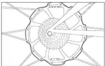
2 Motor
• DC rear hub motor
- Black, nom. 250W, nom. 9Nm / max. 40Nm, 4.7kg
- Brushless, gearless
- Generate mode for energy recuperation
• Integrated torque sensor

3 Console
- Removable
- Illuminated LCD display with battery state of charge
• 4 assistance levels - 4 generate levels
- Backlight controls
- Offers cycle computer functions (speed, odometer, average speed, total distance)

natural_image
Line drawing of a Bion device with a cable and connector (no text or symbols)4 Brake switch
- A sensor integrated with the brake lever – connected to the BionX console
- Upon activation assistance is shut off ("kill switch") generate mode is activated
Power Supply
• Power supply to recharge the LiMn-battery
• Input voltage: 100-240V
• Output voltage: 26V
• Max. charge current: 3.45A
- Output: 90W
Inserting or Removing the Console

natural_image
Line drawing of a device with a labeled component 'StonX' and a monitor on top (no text or symbols beyond label)
natural_image
Diagram of a device with an upward arrow and a small inset showing a component (no text or symbols)Inserting the console
- Slide the console into the console mount on the handlebar
- Make sure that the console engages securely. When inserted correctly, you will hear an audible "click".

natural_image
Line drawing of a printer or printer with an arrow pointing to the front panel (no text or symbols present)
Removing the console
- Release the console by pushing the release lever on the console mount
- Slide the console out of the console mount
Inserting the battery
1 Place battery onto the docking station
2 Slide the battery down the rail gently towards connector
3 The release arm will close automatically as battery slides towards connector

Do not force the battery arm closed, this can bend the battery connector
4 With the release arm almost closed, hold it in place and simultaneously press in the lock cylinder – you will hear an audible >click< when the battery is properly inserted


natural_image
Line drawing of a mechanical component with an arrow and numbered point (no text or symbols)
Removing the battery
1 Turn off the BionX propulsion system (no illustration)
2 Lightly press on the battery release arm, insert the key and turn clockwise
3 The lock cylinder will protract, freeing battery release arm (no illustration)
4 Remove the battery by opening release arm
5 Lift the battery from dock by sliding upwards
6 Remove the battery


natural_image
Technical line drawing of a mechanical component with an arrow indicating direction (no text or symbols)
WARNING
BionX batteries shall only be recharged with BionX chargers or BionX power supplies.
Never short circuit the battery by connecting the contacts of the battery. Never open the battery. This could damage the battery and possibly lead to overheating or ignition of the battery. The battery cannot be serviced by the user. Opening the battery case voids all warranty and product liability claims. Never use a battery which has obvious damage to the housing or the connector.
Make sure that the battery is no longer connected to the power supply once the charging operation is complete. The Lithium Manganese battery cells have a low self-discharge rate, therefore a continuous connection of the battery to the power supply is not necessary. We recommend that you fully charge the battery when it will not be used for a longer period of time, for example, before storing it for the winter, and then recharge the battery at minimum every three months.
It is best to store the battery in a cool location at temperatures between 10 °C and 25 °C. Never store the battery in locations where the temperatures can reach more than 45 °C or fall below -10 °C. The battery should never be exposed to extreme temperature fluctuations or humidity, and always protect the battery during storage from humidity to prevent corrosion on the connectors. Never drop the battery, and protect it from physical damage. Damage may lead to short-circuits, and as a result cause overheating or ignition of the battery.

Used batteries may not be disposed of in regular household trash!
Be aware that used batteries must be disposed of properly!
DERBY BionX batteries can be returned at DERBY dealerships free of charge.
Charging the battery:

WARNING
Only use the BionX power supply that was supplied with the bicycle to charge the battery. The use of other power supplies can damage the battery.
The BionX power supply should be used exclusively for rechargeable batteries of the specified type. The use of the BionX power supply with batteries that are not rechargeable may damage those and could lead to overheating, or ignition of the battery. Keep the power supply away from water or moisture when charging and/or connected to prevent electrical shock or short-circuits.
Do not use a power supply that has obvious signs of damage to the cable, housing or the connector.
Extreme temperatures will affect battery life, especially during charging. Avoid charging in direct sunlight or in very hot or cold temperatures. This will reduce the life of the battery considerably. We recommend charging the battery at temperatures around 20 °C (room temperature). The battery should be warmed to room temperature before it is charged, particularly when it was exposed to cold temperatures during a ride.
The battery can be charged when mounted on the bicycle or removed from the battery docking station. A Lithium Manganese battery does not have a memory effect, which means that the battery's maximum energy capacity is not affected if it is repeatedly recharged after only being partially discharged. The battery does not need to be completely drained before charging. We recommend charging the battery after every ride, preferably when the battery state of charge display shows less than 50%. We recommend that you fully charge the battery when it will not be used for a longer period of time, for example, before storing it for the winter, and then recharge the battery at minimum every three months. When the battery is depleted to the level where there is risk it could fall into deep discharge, the battery will signal that a recharge is needed by beeping.
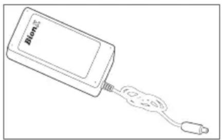
natural_image
Line drawing of a device with a label 'BIOM' and connected to a USB cable (no text or symbols on the device itself)Power Supply
The delivered power supply is suitable for the voltage ranges 110-115V or 220-230V. There is no need to manually set the voltage range.
Charging procedure

natural_image
Technical line drawing of a cylindrical mechanical component with threaded end (no text or symbols)
amber = charging
- Connect power supply and battery by inserting the charge connector into the touch port – the system can be turned on or off
- Connect the plug of the power supply with the power outlet
- The battery touch port (LED ring around the charging connector) lights up according to the actual state of charge of the battery and then turns to AMBER during the charging process
- After a complete charge the colour of the LED ring changes to GREEN. The battery is then fully charged and the charging process is complete
• Following this procedure the charging connector should be disconnected - During the charging process you can check the battery state of charge through the console if the battery is connected to the system - system can be switched on while it is charged
The battery is fully charged after about 3 to 4 hours. Make sure that a completely charged battery is no longer connected to the charger after the charging procedure is completed.
Checking Battery State of Charge
- Swipe your finger slowly over the touch port.
• Battery state of charge LED will illuminate.
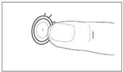
natural_image
Simple line drawing of a finger pressing a circular button (no text or symbols)| Battery state Colour | |
| 100-85 % green | |
| 85-25 % amber | |
| < 25 % red |
Assist Mode / Generate Mode
The BionX propulsion system operates in four assist levels in the assistance mode, and in four charging levels in the generate mode. In the assistance mode, your pedalling is assisted proportionally by an electric motor that drives the rear wheel. A torque sensor is located on the axle of the electric motor and measures the effort provided by the rider; this produces natural feeling assistance from the motor.
When in generate mode the electric motor functions as a generator and recharges the battery. When going downhill, you can regulate your speed by varying the generate level. This generate function provides a certain braking effect, however it does not replace legally required brakes. If either one of the two brake levers (depending on bike model) is pulled, the drive system automatically enters generate mode. The range can therefore be extended up to 15%, depending on the road conditions.
| Assistance Level (A) Degree of Assist Riding Situation | |
| 1 35% Riding on level ground | |
| 2 75% Slight inclines, head wind | |
| 3 150% Steep hills, strong head wind | |
| 4 300% Very steep roads | |
| Generation Level (G) | |
| 1 Slight downhill grade, tailwind | |
| 2 Significant downhill grade, tailwind | |
| 3 Steep descent | |
| 4 Very steep descent |
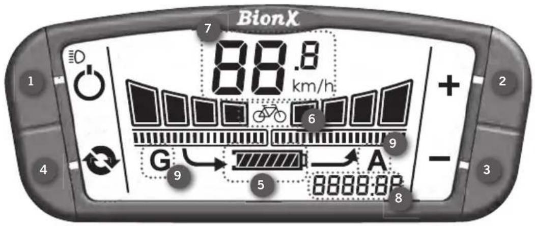
- Ⓧ Power
-
- Key
-
- Key
- Cycle
-
State of charge indicator
-
(bicycle) mode
- Speedometer
- Tripdistance/odometer/chronometer/average speed
- Assist (A) or generate level (G)

Turn the system on
Briefly push either the key or key. The battery will beep 4 times and you will see a countdown, this is the system performing a self-check. After startup, the system is always in mode (no motor assist/bike operation). To turn the system off, briefly push. The battery will beep 5 times. After 10 minutes of "no operation" the system turns off automatically.

Select assistance/generate level
Push 🔊 key for more/less assist (see bar "fi elds 1-4" above display "A"). From ⏱ mode push key to enter continuous generate mode.
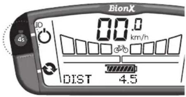
Turn on display backlight
Push and hold ⏻ key for 4 seconds - display backlight is turned on.
Turn off display backlight
Push and hold ⏻ key again for 4 seconds.

Select the cycling computer functions
Briefly push the key to change between:
| TripDistanceDIST | |
| Odometer ODO | |
| Chronometer CHRONO | |
| Average Speed AVSPD | |

To reset cycle computer functions
Hold the key for a few seconds to reset the distance, chronometer, and average speed values to zero.
In general, all basic settings for your electric bicycle are pre-set. If you happen to change tire sizes, during service, for example, you can reset the tire circumference to ensure the precise function of your speedo-meter. Furthermore, you can set the unit to display the speed, the strength of the recharge when triggering one of the two brake levers and the arrangement of the main functions. This is done by entering programming codes.
Turn on the programming mode
Simultaneously push and until the display shows "0000". The first zero blinks. Change the value of the selection with for and confirm with . Select the other digits in the same manner until the desired program is displayed.

| Code Description |
| 2001 Select km/h or mph |
| 2002 Regeneration/brake output (for magnetic switch) 0-40 (ideally 30-40) |
| 2005 Tire circumference (millimeters) |
| 2009 Flip Display Plus/Minus 0 = power left, 1 = power right |
| Code 2001 Code 2002 | |
| Select unit - km/h or mph. Select with + or - and confi rm with ⏻ | Default value: 30: adapt with + and -. Confi rm with ⏻ |
| Code 2005 Code 2009 | |
| Set tire size (in mm) - Select digits one after another with + or - and confi rm with 🔊. | Current setting of main functions is displayed. Flip = 0, assist toggle is on the right side of console; Flip = 1, assist toggle is on the left side of console. Confi rm with 🔊 |

WARNING
Please do not use other programming codes without consulting your authorized dealer. If you type the wrong code, please push key to exit programming mode.
We recommended the removal and installation of the rear wheel to be done by a qualified dealer.
Should you have to do this yourself, please follow the instructions below:

WARNING
Always turn off the propulsion system prior to plugging in or unplugging the motor cables.

CAUTION
It is absolutely essential that the axle nuts are tightened with a torque of 40Nm/30lb-ft; this ensures that the propulsion system functions properly. Ensure the torque reaction collar is fully inserted into the dropout.
Hydraulic disc brake: Do not pull the brake lever with the brake disc on the rear wheel removed from the caliper. Insertion of the wheel can be difficult or impossible as the brake pads will prevent brake disc from sliding in place.
To Remove the rear wheel
• Make sure that the system is turned off
- Remove the neoprene covers (Fig. 1)
• Unplug the two cable connections that lead to the motor (Fig. 2)
First COMMUNICATION 1, then POWER 2
- Disconnect the cable guide from the rear wheel brake (only on bicycles with V-brakes)
- Loosen the axle nut on the rear wheel using a 15mm ring wrench (Fig. 3)
- Slide the rear wheel downwards out of the drop out

natural_image
Technical line drawing of a mechanical component with no visible text or symbols
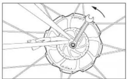
natural_image
Technical line drawing of a mechanical gear assembly with no visible text or symbols
natural_image
Technical line drawing of a mechanical component with rotating arms and internal blades (no text or symbols)Installing the rear wheel
- Guide the rear wheel axle into the two dropouts and make sure that the brake disc (on models with disc brakes) is inserted between the brake pads
- Also make sure that the flat area at the left of the rear axle (torque reaction collar) is aligned so that it fits into the left dropout
• Install the rear wheel with both sides of the axle inserted all the way in the dropouts - Tighten the axle nuts on the rear wheel with 40Nm/30lb-ft (= VERY TIGHT!). This torque is essential for the correct function of the propulsion system. If you do not have a torque wrench, use a normal ring wrench. Have your dealer check the torque of the axle nuts as quickly as possible. Use only the original axle nuts; otherwise you run the risk of damaging the axle threads.
- Keep the motor cables clear of the brake disc (on models with disc brakes)
- Plug in the cable connections (POWER ^1 before COMMUNICATION ^2 ) and place the larger neoprene cover over the plug-in connections, and the smaller neoprene cover closer to the disc to prevent the cables from wear.
- Now replace the cable pull. Re-install the cable guide of the rear wheel brake (V-brakes only), and correctly adjust the rear wheel brake.
Maintenance and Care
We recommend to have the spoke tension of the rear wheel and the torque of all screws checked by your qualified dealer after the first 200km.
In order to ensure extended use of the propulsion system, all plug-in contacts of the system should be checked every two to three months and cleaned with a soft and dry brush, if necessary. It must be ensured that no dirt or humidity penetrates the battery docking station when the battery is removed. The electric motor is a brushless DC-motor that does not have to be serviced.

CAUTION
Never use a high pressure washer or a garden hose to clean the propulsion system. The force of a water jet could damage the electrical components of the propulsion system.
We recommend a soft sponge or a soft brush to clean the bicycle. Use a moist rag to clean the battery's docking station. Always use very little water and keep water away from the electrical contacts. Check the plug-in connections for moisture after cleaning and let these dry, if necessary, before reusing the bicycle.
Transporting an Electric Bicycle on a Car

WARNING
Make absolutely sure that the bike rack on your car is suitable for the increased weight and the unique frame style of your electric bicycle. A rack that is not suitable can be damaged or even break during the transport of the electric bicycle. The electric bicycle can be damaged by an unsuitable bike rack.
For transportation of the electric bicycle on a bike rack always remove the battery and the console.
Repair and Spare Parts
For repair of your electric bicycle consult your qualified dealer. All of the original spare parts for your electric bicycle can be purchased through your dealer. If you need spare keys for the battery, please contact your dealer. Please retain the key number for your records.

BionX Key Number
The system does not turn on
Check the battery and make sure that it is charged. The battery must be correctly inserted in the docking station and the lock must be completely closed. Also check that all connectors of your wiring harness are properly engaged. If the problem persists, contact your authorized dealer.
The system can be turned on but there is no assist
Check that the cables running from the battery to the motor are properly connected. If the problem persists, contact your authorized dealer.
The system is continuously in generate mode
When the propulsion system is continuously in generate mode and cannot be switched back to assist mode by pushing the +key, the problem most likely lies with the brake switches that are located at the brake levers. In this case try to "repair" the system by turning it off and then on again. If that does not solve the problem, you can temporarily bypass it by removing the plug-in connection from the console to the brake-switch.

WARNING
If you bypass the brake switches you also disable regenerative breaking.
In doing so your system will not provide any brake support.
We recommend that you contact your dealer as soon as possible.
The motor is not as powerful after a repair or service
Tighten the nuts of the rear axle with the specified torque (40Nm/30lb-ft). If the problem is not solved please contact your dealer.
The battery state of charge display on the console does not show "full" after a complete charging procedure
Make sure that you have followed all of the instructions for the charging procedure. Let the battery cool off for a few hours and then recharge it again. If the problem's still not solved, let the battery cool again, fully deplete the battery and charge it again. If the problem persists, contact your authorized dealer.
- The BionX warranty covers a two-year period for BionX propulsion system(s) within the framework of the following conditions.
- This warranty exclusively covers systems provided by BionX excluding all the other bicycle components provided by other bicycle manufacturers.
- This warranty covers the repair and/or the replacement of BionX propulsion systems provided that the equipment concerned loses its functionality within the agreed warranty period and also provided that the claim is not related to any of the following cases expressly excluded under this warranty.
- Any other legal provisions, particularly with respect to warranty regulations, are not restricted by this warranty.
- This warranty only covers material and manufacturing defects. It is only effective with a valid proof of purchase consisting of the original purchase document or receipt indicating the date of purchase, the dealer's name and the designation of the bicycle model. BionX reserves the right to reject the coverage of this warranty if the accompanying documentation of BionX components is not accurate or complete.
- In the case of a warranty claim, BionX undertakes to either repair faulty system components and/or to replace such components, at BionX discretion (Service Replacement Unit).
- Warranty repairs have to be exclusively performed by BionX. Any component to be repaired under the framework of this warranty has to be transferred to BionX at the client's own expenses and risks, and, after the completion of such repair, has to be picked up at BionX, or, it has to be shipped (at the request of the client) to the client's address at the client's own expenses and risks. In the case of rightful warranty claims, BionX reserves the right to bear or repay transportation expenses. In order to have a previous determination whether a warranty claim is justified or not, the end user has to submit his claim to the dealer from whom he purchased the product so that the respective dealer handles the shipment to BionX.
- Costs for repair work performed in advance by persons who have not been authorized by BionX will not be reimbursed. In such a case, any warranty claim will cease.
- Repair work and/or replacement of components during the warranty period do not lead to an extension and/or a new start of the warranty period. Repair work and direct replacement during the warranty period may be performed with functional replacement components of equal value.
-
The two-year warranty period starts with the date of purchase. Warranty claims must be reported immediately.
-
No warranty claims are accepted - without limitation to other reasons - in the case of damages due to the following:
a) External influences, particularly falling rocks, collision, accident and other external events with an immediate external effect due to mechanical powers.
b) Purpose and/or malevolent acts, theft and robbery as well as natural hazard events and/or acts of mischief.
c) Test, maintenance, repair and replacement work due to normal use.
d) If the battery/cell pack does not provide full capacity in the course of normal use or for batteries going through a normal aging process or reduction of performance, BionX warranty only covers that within the two-year warranty period or after 600 charging cycles, whichever event occurs first, to the condition that the battery still provides at least 70% of its initial capacity.
e) In the case of inappropriate use, e.g. the product was exposed to liquids, chemicals of any type and/or extreme temperatures, wetness and humidity and/or if the battery suffers damages due to non-compliance with the special instructions set forth in the chapter “Handling and Charging of the Battery”.
f) The model, serial or product number on BionX product has been changed, deleted, blurred or removed. The seal (serial number sticker) on the battery housing has been broken or obviously manipulated.
g) Use of the battery in systems that are not approved for such use with this particular product.
h) Operation of the BionX system with batteries other than the batteries designed for the BionX system.
i) Damages to the battery due to overcharging or not adhering to the instructions of battery handling (refer to user manual).
- This warranty only covers the above mentioned repair work and/or the replacement of defective or compromised components. It excludes any claims as to the reimbursement of property damages, downtimes, expenses for renting or leasing equipment, travel expenses, lost profit or any other claims. BionX liability in connection with this warranty is limited to the respective acquisition value of the product.
BionX, BionX Design and powered by BionX are trademarks
of BionX International Corporation.
DERBY CYCLE
powered by
BionX
Your dealer

natural_image
Illustration of various electronic components including a power supply unit, motor, and charging device (no text or symbols visible)Robert Bosch GmbH
Bosch eBike Systems
72703 Reutlingen
Germany
www.bosch·ebike.com
0 276 001 X45 (2011.09) T / 172
HMI | Drive Unit 45 | Battery Pack | Charger
1 270 020 900 | 0 275 007 003 |
1 270 020 500 | 1 270 020 501 | 1 270 020 502 | 1 270 020 503
1 270 020 504 | 1 270 020 505 | 1 270 020 506 | 1 270 020 507 |
0 275 007 900

BOSCH
Dover 125th Impulse, Dover Premium Impulse, Dover XXL Impulse, Dover HS Impulse, Impulse XXL, Impulse, Impulse HS, Impulse Compact, Leeds Compact, Dover Impulse


F


Drive HMI/Drive Unit 45
Safety Notes

Read all safety warnings and all instructions. Failure to follow the warnings and instructions may result in electric shock, fire and/or serious injury.
Save all safety warnings and instructions for future reference.
The term “battery” used in these operating instructions refers both to standard batteries (batteries with holder on the bike frame) and to rear rack batteries (batteries with holder under the rear rack).
Do not open the drive unit yourself. The drive unit is maintenance-free and may be repaired only through a qualified repair person and only using original spare parts. This will ensure that the safety of the drive unit is maintained. Unauthorised opening of the drive unit will void any and all warranty claims.
All components mounted to the drive unit and all other components of the eBike drive (e.g., the chainwheel, chainwheel seat, pedals) may be replaced only against identical components or components specifically approved for your eBike by the bicycle manufacturer. This protects the drive unit against overload and damage.
Remove the battery from the eBike before working on the eBike (e.g., assembling, maintenance, etc.), transporting it via car or plane or storing it. Danger of injury when accidentally actuating the On/Off switch.
The start-assistance function may only be used when starting or pushing the eBike. Danger of injury when the wheels of the eBike do not have ground contact while using the start-assistance function.
▶ Use only original Bosch batteries approved for your eBike by the manufacturer. Using other batteries can lead to injuries and pose a fire hazard. When using other batteries, Bosch shall not assume any liability and warranty.
▶ Please observe all national regulations on registering and using eBikes.
▶ Please read and observe the safety warnings and instructions enclosed in the operating instructions of the battery as well as in the operating instructions of your eBike.
Product Description and Specifications
Intended Use
The drive unit is intended exclusively for your eBike and may not be used for other purposes. The eBike is intended for use on paved paths. It is not permitted for use in competition.
Product Features (see page 2-3)
The numbering of the product features refers to the illustrations on the graphics page. All representations of bike components, with exception of the drive unit, drive HMI, speed sensor and corresponding holders, are schematic and can deviate from your eBike.
1 Drive HMI
2 Holder for drive HMI
3 "info/reset" button for multi-function indicator
4 "mode" assistance button
5 "light" button
6 Increase-assistance-level button/Start-assistance On/Off button
7 Decrease-assistance-level button
8 Drive unit
9 Bottom holder screw
10 Upper holder screw
11 Speed sensor
12 Spoke magnet of the speed sensor
Indication Elements, Drive HMI
a Speed indication
b Light indicator
c Assistance-level indicator
d Start-assistance indicator
e Multi-function indicator
f Assistance-mode and error code indicator
g Battery charge control indicator
Technical Data
| Drive Unit Drive Unit 45 | |
| Article number | 0 275 007 003 |
| Rated continuous output | W 350 |
| Output torque, max. | Nm 50 |
| Rated voltage | V= 36 |
| Operating temperature | °C -5...+40 |
| Storage temperature | °C -10...+50 |
| Degree of protection | IP 54 (dust and splash water protected) |
| Weight, approx. | kg 4 |
| Drive HMI HMI | |
| Article number | 1 270 020 900 |
| Operating temperature | °C -5...+40 |
| Storage temperature | °C -10...+50 |
| Degree of protection | IP 54 (dust and splash water protected) |
| Weight, approx. | kg 0.15 |
| Lighting* | ||
| Rated voltage V=6 | ||
| Power output | ||
| - Front light | W | 2.7 |
| - Rear light | W | 0.3 |
* Not possible via the eBike battery in all country-specific versions, depending on the statutory regulations
Assembly
Inserting and Removing the Battery
For inserting and removing the battery in/from the the eBike, please read and observe the battery operating instructions.
Positioning the Holder of the Drive HMI
▶ Tighten screws 10 and 9 with a tightening torque of 1 Nm (max.). Otherwise, the holder 2 can become damaged.
Moving/Tilting the Holder (see figure A)
Loosen both screws 9 on the bottom side of holder 2. Move the holder on the handlebar or change the holder angle. Retighten both screws 9 again with a tightening torque of 1 Nm (max.).
Turning the Holder (see figure B)
Loosen screw 10 on the top side of holder 2. Turn the top part of the holder in such a manner that the drive HMI 1 is well in your view after inserting it (see "Inserting and Removing the Drive HMI"). Retighten screw 10 again with a tightening torque of 1 Nm (max.).
Inserting and Removing the Drive HMI (see figure C)
To insert the drive HMI, place it turned by approx. 30^ onto holder 2 and then turn it clockwise to the stop.
To remove the drive HMI, turn it approx. 30° anticlockwise and pull it out of the holder 2.
▶ Remove the drive HMI when parking the eBike, so that the drive cannot be used by unauthorised persons. Without the drive HMI, the drive cannot be switched on.
Checking the Speed Sensor (see figure D)
The speed sensor 11 and its spoke magnet 12 must be mounted in such a manner that the spoke magnet, after a turn of the wheel, moves past the speed sensor with a clearance of at least 5 mm, yet no more than 17 mm.
Note: If the clearance between speed sensor 11 and spoke magnet 12 is too small or too large, or if the speed sensor 11 is not properly connected, the speed indication a will fail, and the eBike drive will operate in emergency mode. In this case, loosen the screw of the spoke magnet 12 and fasten the spoke magnet to the spoke in such a manner that it runs past the mark of the speed sensor at the correct clearance. When the speed is still not being indicated in the speed indication a after this, please refer to an authorised bicycle dealer.
Operation
Initial Operation
Requirements
The drive of your eBike can only be activated when the following requirements are met:
– A sufficiently charged battery is inserted (see operating instructions of the battery).
- The drive HMI is properly inserted in the holder (see “Inserting and Removing the Drive HMI”, page English-2).
- The drive HMI is properly connected (see "Checking the Speed Sensor", page English-3).
Switching the Drive On/Off
Insert the battery into the holder and switch it on via the On/Off button (see operating instructions of the battery).
Note: When switching on the battery, the pedals of the eBike may not be subject to load, as otherwise the output capacity of the drive will be limited.
If the battery was inadvertently switched on with load applied to the pedals, then switch it off and then on again without load.
Switching on the battery also switches on the display of the drive HMI. The drive HMI indicates the charge condition of the battery as well as the settings of the drive unit.
The drive is activated as soon as you step into the pedals (except when in start-assistance mode, see “Switching Start-assistance On/Off”, page English-4). The assistance level depends on the settings of the drive HMI.
As soon as you stop pedaling when in normal operation, or as soon as you have reached a speed of 45 km/h, the assistance from the eBike drive is switched off. The drive is automatically re-activated as soon you start pedaling again and the speed is below 45 km/h.
To switch off the drive, switch the battery off via the On/Off button (see operating instructions of the battery).
When no power output of the drive is requested for approx. 10 minutes, (e.g., because the eBike is parked), the battery automatically switches off to save energy.
Indications and Settings of the Drive HMI
Note: Indications and settings on the drive HMI are only possible when the eBike battery is switched on. The drive HMI does not have an own power supply.
Charge Condition of the Battery
Besides on the charge-control indicator on the battery itself, the charge condition can also be read from indicator g of the drive HMI.
On indicator g, each bar of the battery symbol is equivalent to a capacity of approx. 20 %:

100 % to 80 % capacity

20 % to 5 % capacity; the battery should be recharged.

Less than 5 % capacity; drive assistance is no longer possible. The LEDs of the
charge-control indicator on the battery go out. When the eBike lighting is powered via the battery (country-specific), the capacity upon first indication of the empty battery symbol will be sufficient for approx. 2 hours of lighting. When the symbol begins to flash, the lighting will continue to operate only for a short period.
Adjusting the Assistance Mode
The level of assistance of the eBike drive when pedaling can be adjusted via the drive HMI.
Note: For individual versions, it is possible that the the assistance mode is pre-set and cannot be changed. It is also possible that less modes are available for selection than listed here.
A maximum of four assistance modes are available:
ECO
“ECO”: Effective assistance at maximum efficiency for maximum cruising range
FOUR
"TOUR": Uniform assistance, for touring with long cruising range
SPORT
"SPORT": Powerful assistance for sportive riding off road as well as for urban traffic
SPEED
"SPEED": Maximum assistance, supporting highest cadence for sportive riding
To change the assistance mode, press the
“mode” button 4 until the desired mode is displayed in indicator f.
While using the start-assistance function, indication f goes out; the set assistance mode is stored.
Adjusting the Assistance Level
In the set assistance mode, the assistance level can be adjusted anytime, even during riding.
Note: For individual versions, it is possible that the assistance level is pre-set and cannot be changed.
A maximum of three assistance levels as well as the assistance shut-off are possible.
| Assistance degree* at: | Assistance level |
| Assistance mode “1” “2” “3” | |
| “ECO” | 30 % 60 % 100 % |
| “TOUR” | 45 % 80 % 120 % |
| “SPORT” | 70 % 140 % 180 % |
| “SPEED” | 90 % 160 % 250 % |
| * The assistance degree can vary for individual versions. | |
To increase the assistance level, press the ▲ button 6 until the desired level is displayed in indicator c.
To decrease the assistance level, press the ▼ button 7 until the desired level is displayed in indicator c.
In assistance level “0”, the drive is switched off. The eBike can be operated as a normal bicycle through pedaling.
While using the start-assistance function, indication c goes out; the set assistance level is stored.
Switching Start-assistance On/Off
Start-assistance can be used for additional support on the first meters when starting is difficult (e.g., at a traffic light or when starting uphill). It can also be used as a pushing aid when in the lowest gear.
The start-assistance function may only be used when starting or pushing the eBike. Danger of injury when the wheels of the eBike do not have ground contact while using the start-assistance function.
To activate the start-assistance function, press the ▲ button 6 longer than 1 second and continue to hold. The eBike drive is activated, indicator d flashes and indicators c, e and f go out.
Start-assistance is switched off as soon as any of the following points occur:
- You release button

- You press another button on the drive HMI,
- You pedal in forward or quickly in backward direction,
- The wheels of the eBike are blocked (e.g., through braking or running against an obstruction),
- After achieving a speed of 16 ~km / h .
Switching the Lighting On/Off
Depending on country-specific regulations, two lighting versions are possible:
- The front light, rear light and display lighting can be switched on and off at the same time via the drive HMI.
- Only the display lighting can be switched on and off; the front and rear light of the eBike are independent of the drive HMI.
For both versions, the lighting is switched on by pressing the "light" button 5. The lighting indicator b appears on the display.
To switch off the lighting, press the "light" button 5 again; the lighting indicator b goes out.
Speed and Distance Indicators
Note: Depending on country-specific version, distance and speed can either be displayed in "km" and "km/h" or in "mi" and "mph". Adjustment of the drive HMI and the selection of the display possibilities for the km and mile version are identical.
The speed indication a always displays the current speed.
The following indications are available in multifunction indicator e:
^odo 01635km
Total distance “odo”: Indicates the total distance covered with the eBike
trip068.50km
Trip distance "trip": Distance covered since the last reset
Error Code Indication
The components of the eBike drive are continuously and automatically monitored. When an error is detected, the respective error code is indicated in display f.
Depending on the type of error, the drive is automatically shut off if required. Continued travel without assistance from the drive is possible at any time. However, have the eBike checked before attempting new trips.
avg0021.7km/h
Average speed "avg": Average speed achieved since the last reset
00072 ^ran km
Range "range": Estimated range of the available bat-
tery charge (for constant conditions such as assistance mode, assistance level, route profile etc.)
To switch within the multi-function indicator, press the "info/reset" button 3 until the desired function is displayed.
To reset the trip distance "trip" and the average speed "avg", switch to one of both indications and then press the "info/reset" button 3 until the indication is reset to zero.
While using the start-assistance function, multi-function indicator e goes out.
▶ Have all inspections and repairs carried out only by an authorised bicycle dealer. When an error is still displayed despite corrective measures, please also refer to an authorised bicycle dealer.
Code Cause Corrective Measure
| 001 | Internal error of the drive HMI | Have the drive HMI checked |
| 002 | One or more buttons of the drive HMI are blocked. | Check if any buttons are blocked, e.g. from dirt or debris. Clean the buttons, if required. |
| 003 | Connection problem of the drive HMI | Have connections and contacts checked |
| 100 | Internal error of the drive unit | Have the drive unit checked |
| 101 | Connection problem of the drive unit | Have connections and contacts checked |
| 102 | Error of the speed sensor | Have the speed sensor checked |
| 103* | Connection problem of the lighting system | Have connections and contacts checked |
| * only for eBike lighting via battery (country-specific) | ||
| Code Cause Corrective Measure | ||
| 104 | Connection problem of the drive HMI | Have connections and contacts checked |
| 105 | Temperature of the drive unit too high (above 40 °C) | Allow the drive unit to cool down. Continued travel without assistance from the eBike drive is possible and speeds up the cooling of the drive unit. |
| 200 | Internal electronics error of the battery | Have the battery checked |
| 201 | Temperature of the battery too high (above 40 °C) | Allow the battery to cool down. Continued travel without assistance from the eBike drive is possible and speeds up the cooling of the battery. |
| 202 | Temperature of the battery too low (below -10 °C) | Allow the battery to warm up slowly in a warm location. |
| 203 | Connection problem of battery | Have connections and contacts checked |
| 204 | Incorrect battery polarity Charge the battery with the original Bosch charger as described in the operating instructions. | |
* only for eBike lighting via battery (country-specific)
Notes on Riding with the eBike Drive
When does the eBike Drive Operate?
The eBike drive supports you when riding, as long as you step into the pedals. Without pedaling, there is no assistance. The degree of assistance always depends on the amount of your pedaling power.
When applying less pedaling power, the assistance or support will be lower than when applying a lot of pedaling power. This applies independent of the assistance mode and level.
The eBike drive automatically switches off at speeds in excess of 45 km/h. When the speed falls below 45 km/h, the drive is automatically available again.
An exception applies for the start-assistance function, in which the eBike can be driven at low speed without pedaling.
The eBike can also be ridden as a normal bicycle without assistance at any time, by either switching off the battery or setting the assistance level to "0". The same applies when the battery is empty.
Interaction of the eBike Drive with the Bicycle Gears
The bicycle gears should be used as with a normal bicycle, even with eBike drive (please observe the operating instructions of your eBike).
Independent of the type of gearing, it is recommended to briefly interrupt the pedaling while changing gears. This makes changing gears easier and reduces the wear of the drive train.
By selecting the right gear, you can increase the speed and range with the same pedaling effort.
Gathering First Experience
It is recommended to gather first experience with the eBike away from roads with heavy traffic.
Try out the different assistance modes and assistance levels. As soon as you feel safe, you can participate in traffic with the eBike as with any other bicycle.
Test the operating range of your eBike under different conditions before planning longer and more challenging rides.
Influences on the Operating Range
With a fully charged battery and an efficient riding manner, an operating range of up to 105 km is possible.
However, the operating range depends on many factors, such as:
- Assistance mode and level
– Gear-switching behaviour,
– Bicycle tires and tire pressure,
– Age and condition of the battery, - Route profile (inclines) and road or path conditions (road or path surface),
- Head wind and ambient temperature,
- Weight of the eBike, rider and equipment/luggage
For these reasons, it is not possible to predict an accurate operating range before starting your ride. General rules:
- For the same assistance level of the eBike drive: The less power or force that you have to bring about to reach a certain speed (e.g. through optimal use of the gears), the less energy the eBike drive will consume, and the greater the range for a battery charge.
- The higher the selected assistance degree (assistance mode and level) under otherwise same conditions, the lower the range.
Careful Handling of the eBike
Please observe the operating and storage temperatures of the eBike components. Protect the drive unit, drive HMI and battery against extreme temperatures (e.g. from intense sunlight without adequate ventilation). The components (especially the battery) can become damaged through extreme temperatures.
Maintenance and Service
Maintenance and Cleaning
Keep all components of your eBike clean, especially the battery contacts and corresponding holders. Clean them carefully with a soft, damp cloth.
All components including the drive unit may not be immersed in water or cleaned with a high-pressure cleaner.
For service or repairs on the eBike, please refer to an authorised bicycle dealer.
After-sales Service and Customer Assistance
In case of questions concerning the eBike drive and its components, please refer to an authorised bicycle dealer.
For contact data of authorised bicycle dealers, please refer to www.bosch-ebike.com
Transport
The batteries are subject to the Dangerous Goods Legislation requirements. Private users can transport the batteries by road without further requirements.
When being transported by commercial users or third parties (e.g. via air transport or forwarding agency), special requirements on packaging and labelling must be observed (e.g. ADR Regulations). For preparation of the item being shipped, an expert for hazardous material can be consulted as required.
Use the batteries only when the housing is undamaged. Tape or mask off open contacts and pack up the battery in such a manner that it cannot move around in the packaging. Please also observe possibly more detailed national regulations.
In case of questions concerning transport of the batteries, please refer to an authorised bicycle dealer. Bicycle dealers can also provide suitable transport packaging.
Disposal

The drive unit, drive HMI, battery, speed sensor, accessories and packaging should be sorted for environmental-friendly recycling.
Do not dispose of eBikes and their components into household waste!
Only for EC countries:

According to the European Guideline 2002/96/EC, electrical devices/tools that are no longer usable, and according to the European Guideline 2006/66/EC, defective
or used battery packs/batteries, must be collected separately and disposed of in an environmentally correct manner.
Please return batteries that are no longer usable to an authorised bicycle dealer.

Li-ion:
Please observe the instructions in section "Transport", page English-7.
Subject to change without notice.
Lithium-ion Battery Pack
Safety Notes

Read all safety warnings and all instructions. Failure to follow the warnings and instructions may result in electric shock, fire and/or serious injury.
Save all safety warnings and instructions for future reference.
The term “battery” used in these operating instructions refers both to standard batteries (batteries with holder on the bike frame) and to rear rack batteries (batteries with holder under the rear rack), except when explicitly referring to the design type.
Remove the battery from the eBike before working on the eBike (e.g., assembling, maintenance, etc.), transporting it via car or plane or storing it. Danger of injury when accidentally actuating the On/Off switch.
▶ Do not open the battery. Danger of short-circuiting. When the battery has been opened, any and all warranty claims through Bosch shall be invalid.

Protect the battery against heat (e.g., also against continuous intense sunlight), fire and immersing into water. Danger of explosion.
- Keep the battery when not being used away from paper clips, coins, keys, nails, screws or other small metal objects, that can make a connection from one contact to another. Shorting the battery contacts may cause burns or a fire. For short-circuiting damage caused in this manner, any and all warranty claims through Bosch shall be invalid.
▶ Under abusive conditions, liquid may be ejected from the battery. Avoid contact. If contact accidentally occurs, flush with water. If liquid contacts eyes, additionally seek medical help. Liquid ejected from the battery may cause skin irritations or burns.
▶ Vapours can escape in case of damage and improper use of the battery. Provide for fresh air and seek medical attention in case of complaints. The vapours can irritate the respiratory system.
▶ Charge the battery only with chargers recommended by the manufacturer. A charger that is suitable for one type of batteries may create a risk of fire when used with other batteries.
▶ Use the battery only in conjunction with eBikes as recommended by the manufacturer. This is the only way to protect the battery against dangerous overload.
▶ Use only original Bosch batteries approved for your eBike by the manufacturer. Using other batteries can lead to injuries and pose a fire hazard. When using other batteries, Bosch shall not assume any liability and warranty.
▶ Please read and observe the safety warnings and instructions enclosed in the operating instructions of the charger and drive unit/drive HMI (Human Machine Interface), as well as in the operating instructions of your eBike.
Product Description and Specifications
Product Features (see page 4-5)
The numbering of the product features refers to the illustrations on the graphics pages. All representations of bike components, with exception of the batteries and their holders, are schematic and can deviate from your eBike.
13 Holder of the rear rack battery
14 Rear rack battery
15 Operation and charge-control indicator
16 On/Off button
17 Key of the battery lock
18 Battery lock
19 Upper holder of the standard battery
20 Standard battery
21 Bottom holder of the standard battery
22 Carrying strap
23 Battery charger
Technical Data
| Lithium-ion battery Battery Pack | |
| Article number | |
| - Standard battery, black | 1 270 020 500/1 270 020 504 |
| - Standard battery, white | 1 270 020 501/1 270 020 505 |
| - Standard battery, silver | 1 270 020 502/1 270 020 506 |
| - Rear rack battery | 1 270 020 503/1 270 020 507 |
| Rated voltage | V= 36 |
| Rated capacity | Ah 8 |
| Energy | Wh 288 |
| Operating temperature | °C -10...+40 |
| Storage temperature | °C -10...+60 |
| Allowable charging temperature range | °C 0...+40 |
| Weight | kg 2.5 |
| Degree of protection | IP 54 (dust and splash water protected) |
Assembly
▶ Place the battery only on clean surfaces. In particular, avoid contaminating the charge socket and the contacts, e.g. by means of sand or ground.
Checking the Battery Before Using for the First Time
Check the battery before charging it or using it with your eBike for the first time.
For this, press the On/Off button 16 to switch on the battery. When no LED of the charge-control indicator 15 lights up, the battery may be damaged.
When at least one, but not all LEDs of the charge-control indicator 15 is lit, then fully charge the battery before using for the first time.
▶ Do not charge a damaged battery and do not use it. Please refer to an authorised bicycle dealer.
Charging the Battery
▶ Use only the charger listed on the graphics page. Only this charger is matched to the lithium-ion battery used in your eBike.
Note: The battery is supplied partially charged. To ensure full battery capacity, completely charge the battery in the charger before using for the first time.
The battery must be removed from the eBike for charging.
For charging the battery, read and observe the operating instructions of the battery charger.
The battery can be charged any time without reducing the battery life. Interrupting the charging procedure does not cause damage to the battery.
The battery is equipped with a temperature control indicator, which enables charging only within a temperature range between 0 °C and 40 °C. This provides for a long life of the battery.
Charge-control Indicator
When the battery is switched on, the five green LEDs of the charge-control indicator 15 indicate the charge condition of the battery.
In this, each LED indicates approx. 20 % capacity. When the battery is completely charged, all five LEDs light up.
Additionally, the charge condition of the switched on battery is indicated on the drive HMI. Read and observe the and operating instructions of the drive unit and the drive HMI.
When the capacity of the battery is below 5 %, all LEDs of charge-control indicator 15 on the battery go out; however, the drive HMI does provide an additional indication.
Inserting and Removing the Battery (see figures E-F)
▶ Always switch the battery off when inserting or removing it from the holder. When the battery is inserted yet empty, please also observe the drive HMI indication. Otherwise, the battery can become damaged.
In order for the battery to be inserted, the key 17 must be inserted into the lock 18 and the lock must be unlocked.
To insert the standard battery 20, place it via the contacts onto the bottom holder 21 on the eBike. Pivot the battery to the stop into the upper holder 19.
To insert the rear rack battery 14, slide it forwards with the contacts facing ahead until it engages in holder 13 on the rear rack.
Check if the battery is tightly seated. Always lock the battery with lock 18, as otherwise the lock can open and the battery can fall out of the holder.
After locking, always remove the key 17 from the lock 18. This prevents the key from falling out and the battery from being removed from unauthorised persons when the eBike is parked.
To remove the standard battery 20, switch it off and unlock the lock with the key 17. Pivot the battery out of the upper holder 19 and pull it by the carrying strap 22 out of the bottom holder 21.
To remove the rear rack battery 14, switch it off and unlock the lock with the key 17. Pull the battery out of the holder 13.
Operation
Initial Operation
▶ Use only original Bosch batteries approved for your eBike by the manufacturer. Using other batteries can lead to injuries and pose a fire hazard. When using other batteries, Bosch shall not assume any liability and warranty.
Switching On and Off
Before switching on the battery, check that the lock 18 is locked.
Note: When switching on the battery, the pedals of the eBike may not be subject to load, as otherwise the output capacity of the drive will be limited.
To switch on the battery, press the On/Off button 16. The LEDs of indicator 15 light up and at the same time indicate the charge condition.
Note: When the battery capacity is below 5 %, none of the LEDs of charge-control indicator 15 will light up. Only the drive HMI will indicate if the battery is switched on.
Switching on the battery is one of the requirements for starting up the eBike drive. Read and observe the operating instructions of the drive unit and the drive HMI.
To switch off the battery, press the On/Off button 16 again. The LEDs of indicator 15 go out. This also switches off the eBike drive.
When no power output of the drive is requested for approx. 10 minutes, (e.g., because the eBike is parked), the battery automatically switches off to save energy.
The battery is protected against deep discharging, overcharging, overheating and short-circuiting through the “Electronic Cell Protection (ECP)”. In case of hazardous situations, a protective circuit automatically switches off the battery.
Notes for Optimum Handling of the Battery
At least 500 full charging cycles are guaranteed for the battery.
The battery life can be prolonged when being properly maintained and especially when being operated and stored at the right temperatures. Operating temperatures between +5 °C and +35 °C are recommended.
With increasing age, however, the battery capacity will diminish, even when properly maintained.
A significantly reduced operating period after charging indicates that the battery is worn out and must be replaced.
In case the carrying strap 22 of the standard battery widens, please have it replaced by a bicycle dealer.
Recharging the Battery prior to and during Storage
When not using the battery for a longer period, charge it to approx. 60 % (3 to 4 LEDs lit on the charge-control indicator 15).
Check the charge condition after 6 months. When only one LED of the charge-control indicator 15 lights up, recharge the battery again approx. 60 %.
Note: When the battery is stored discharged (empty) for longer periods, it can become damaged despite the low self-discharging and the battery capacity may be strongly reduced.
It is not recommended to have the battery connected permanently to the charger.
Storage Conditions
Store the battery in a dry, well-ventilated location. Protect the battery against moisture and water. Under unfavourable weather conditions, it is recommended e.g. to remove the battery from the eBike and store it in an enclosed location until being used again.
The battery can be stored at temperatures between -10 ^ and +60 ^ . For a long battery life, however, storing the battery at a room temperature of approx. 20 ^ is of advantage.
Take care that the maximal storage temperature is not exceeded. As an example, do not leave the battery in a vehicle in summer and store it out of direct sunlight.
Maintenance and Service
Maintenance and Cleaning
Keep the battery clean. Clean it carefully with a soft, damp cloth. The battery may not be immersed in water or cleaned with a water jet.
When the battery is no longer operative, please refer to an authorised bicycle dealer.
After-sales Service and Customer Assistance
In case of questions concerning the batteries, please refer to an authorised bicycle dealer.
▶ Note down the number on the key 17. In case of loss of the keys, please refer to an authorised bicycle dealer, and provide the key number.
For contact data of authorised bicycle dealers, please refer to www.bosch-ebike.com
Transport
The batteries are subject to the Dangerous Goods Legislation requirements. Private users can transport the batteries by road without further requirements.
When being transported by commercial users or third parties (e.g. via air transport or forwarding agency), special requirements on packaging and labelling must be observed (e.g. ADR Regulations). For preparation of the item being shipped, an expert for hazardous material can be consulted as required.
Use the batteries only when the housing is undamaged. Tape or mask off open contacts and pack up the battery in such a manner that it cannot move around in the packaging. Please also observe possibly more detailed national regulations.
In case of questions concerning transport of the batteries, please refer to an authorised bicycle dealer. Bicycle dealers can also provide suitable transport packaging.
Disposal

The batteries, accessories and packaging should be sorted for environmental-friendly recycling.
Do not dispose of batteries into household waste!
Only for EC countries:

According to the European Guideline 2002/96/EC, electrical devices/tools that are no longer usable, and according to the European Guideline 2006/66/EC, defective or used
battery packs/batteries, must be collected separately and disposed of in an environmentally correct manner.
Please return batteries that are no longer usable to an authorised bicycle dealer.
Li-ion:
Please observe the instructions in section "Transport", page English-13.
Subject to change without notice.
Charger
Safety Notes

Read all safety warnings and all instructions. Failure to follow the warnings and instructions may result in electric shock, fire and/or serious injury.
Save all safety warnings and instructions for future reference.
The term “Batterie” used in these operating instructions refers both to standard batteries (batteries with holder on the bike frame) and to rear rack batteries (batteries with holder under the rear rack).

Keep the charger away from rain or moisture. The penetration of water into a battery charger increases the risk of an electric shock.
▶ Only charge Bosch lithium-ion batteries approved for eBikes with the voltages listed in the technical data. Otherwise there is danger of fire and explosion.
▶ Keep the battery charger clean. Contamination can lead to danger of an electric shock.
Before each use, check the battery charger, cable and plug. If damage is detected, do not use the battery charger. Never open the battery charger yourself. Have repairs performed only by a qualified technician and only using original spare parts. Damaged battery chargers, cables and plugs increase the risk of an electric shock.
▶ Do not operate the battery charger on easily inflammable surfaces (e.g., paper, textiles, etc.) or surroundings. The heating of the battery charger during the charging process can pose a fire hazard.
▶ Vapours can escape in case of damage and improper use of the battery. Provide for fresh air and seek medical attention in case of complaints. The vapours can irritate the respiratory system.
▶ Supervise children. This will ensure that children do not play with the charger.
Children or persons that owing to their physical, sensory or mental limitations or to their lack of experience or knowledge, are not capable of securely operating the charger, may only use this charger under supervision or after having been instructed by a responsible person. Otherwise, there is danger of operating errors and injuries.
- Connect the battery charger to a mains supply that is properly connected to earth. Socket and extension cord must have an operative protective conductor.
▶ Please read and observe the safety warnings and instructions enclosed in the operating instructions of the battery and drive unit/drive HMI, as well as in the operating instructions of your eBike.
▶ A short version of important safety warnings in English, French and Spanish with the following content can be found on the bottom side of the charger (marked with number 28 in the representation on the graphics page):
- For safe operation see manual. Risk of electric shock.
- Dry location use only.
- Charge only eBat100-199 rechargeable batteries. Other batteries may burst causing personal damage.
- Do not replace the plug assembly as risk of fire or electric shock may result.
▶ Products sold in GB only: Your product is fitted with an BS 1363/A approved electric plug with internal fuse (ASTA approved to BS 1362).
If the plug is not suitable for your socket outlets, it should be cut off and an appropriate plug fitted in its place by an authorised customer service agent. The replacement plug should have the same fuse rating as the original plug.
The severed plug must be disposed of to avoid a possible shock hazard and should never be inserted into a mains socket elsewhere.
Product Description and Specifications
Technical Data
| Battery Charger Charger | ||
| Article number | 0 275 007 900 | |
| Rated voltage | V=115/230 | |
| Frequency | Hz 50/60 | |
| Battery charging voltage | V=36 | |
| Charging current- Normal-charging operation | A | 4 |
| - Silent-charging operation | A | 1 |
| Allowable charging temperature range | °C 0...+40 | |
| Charge duration (for 8 Ah battery capacity) approx. - Normal-charging operation | h | 2.5 |
| - Silent-charging operation | h | 8 |
| Number of battery cells | 10-80 | |
| Weight according to EPTA-Procedure 01/2003 | kg 0.8 | |
| Protection class | #/I | |
The values given are valid for a nominal voltage [U] of 230 V. For different voltages and models for specific countries, these values can vary.
Product Features (see page 6-7)
The numbering of the product features refers to the illustration of the battery charger on the graphics page.
14 Rear rack battery
15 Battery charge control indicator
20 Standard battery
23 Battery charger
24 Ventilation openings
25 Charger socket
26 Mains voltage selector switch
27 Charger plug
28 Safety warnings, charger
29 Button for charge operation
30 Operation indicator
31 Charge connector
32 Socket for charge connector
Operation
▶ Place the battery only on clean surfaces. In particular, avoid contaminating the charge socket and the contacts, e.g. by means of sand or ground.
Initial Operation
Connecting the Charger (see figures G-H)
Set the voltage of your power source on the mains voltage selector switch 26 of the charger. You can select between 115 V and 230 V.
▶ Observe the mains voltage! The voltage of the power supply must correspond with the data given on the nameplate of the battery charger. Battery chargers marked with 230 V can also be operated with 220 V.
Then, insert the charger plug 27 of the power cord into the charger socket 25 of the charger.
Connect the mains cable (country-specific) to the mains supply. The operation indicator 30 on the charger lights up.
▶ Do not connect the charger to the mains supply until after the correct mains voltage has been set on the mains voltage selector switch 26. Otherwise, the charger can become damaged.
Switch the battery off and remove it from the holder of the eBike. For this, read and observe the operating instructions of the battery.
Insert the charge connector 31 of the battery charger into the socket 32 on the battery. The operation indicator 30 on the charger flashes.
Charging Procedure
The charging procedure begins as soon as the charger is connected with the battery and the mains supply.
Note: The charging procedure is only possible when the temperature of the battery is within the allowable charge-temperature range.
It is possible to select between two charging modes: Normal-charging operation “FAST” and silent-charging operation “SLOW”. In the “SLOW” mode, the charging takes place silently.
| Charge Operation | Normal-charging operation “FAST” | Silent-charging operation “SLOW” |
| Charging current | 4 A 1 A | |
| Operation indicator 30 | flashes continuously lit | |
| Charger ventilation | on off | |
When starting the operation of the charger, normal-charging operation is preset. To change the charging mode, press button 29.
▶ Use caution when touching the charger during the charging procedure. Wear protective gloves. Especially in normal-charging operation with high ambient temperatures, the charger can heat up considerably.
Note: Pay attention that the charger is well ventilated during the charging procedure and that the ventilation openings 24 on both sides are not clogged or contaminated.
During the charging procedure, the LEDs of charge-control indicator 15 on the battery light up. Each continuously lit LED is equivalent to a charge capacity of approx. 20 %. The flashing LED indicates the charging of the next 20 %.
The battery is completely charged when all five LEDs of indicator 15 light up continuously. The charge procedure is automatically ended.
Disconnect the charger from the mains supply and the battery from the charger.
When disconnecting the battery from the charger, the battery is automatically switched off.
The battery can now be inserted into the eBike.
Troubleshooting - Causes and Corrective Measures
Cause Corrective Measure
| Operation indicator 30 not lit, no charging possible | |
| Incorrect mains voltage selected at switch 26 | Select correct mains voltage |
| Plug not inserted correctly | Check all plug connections |
| Contacts of the battery contaminated | Carefully clean the contacts of the battery |
| Battery too warm or too cold | Allow battery to adjust to the ambient temperature until the charge-temperature range is reached |
| Ventilation openings 24 of the charger clogged or contaminated | Clean ventilation openings 24 and set up charger well ventilated |
| Socket outlet, cable or charger defective | Check mains voltage, have charger checked through bicycle dealer |
Battery defective Replace battery
Maintenance and Service
Maintenance and Cleaning
Make sure that the ventilation openings 24 of the charger are not obstructed and clean during use. If required, clean the ventilation openings with a vacuum cleaner.
If the charger should fail, please refer to an authorised bicycle dealer.
After-sales Service and Customer Assistance
In case of questions concerning the charger, please refer to an authorised bicycle dealer.
For contact data of authorised bicycle dealers, please refer to www.bosch-ebike.com
Disposal
Battery chargers, accessories and packaging should be sorted for environmental-friendly recycling.
Do not dispose of battery chargers into household waste!
Only for EC countries:

According to the European Guideline 2002/96/EC for Waste Electrical and Electronic Equipment and its implementation into national right, battery chargers that are no longer usable must be collected separately and disposed of in an environmental correct manner.
Subject to change without notice.
Pack de batteries Lithium-ion Battery Pack
Ladeaggregat Charger
Litiumioniakku Battery Pack
Turvallisuusohjeita

Litiumioniakku Battery Pack
- Bruksanvisning
- Cykelväxlar
- Kedjeväxel
- Bästa kund,
- 8Felavhjälpning20
- Laddabatteriet
- User Manual Pedelec with front motor
- Dear Customer,
- Content
- EC Declaration of Conformity
- Assistance by the electric motor
- EC Declaration of Conformity 2012 CE
- EC Declaration of Conformity 2013 CE
- Quickstart
- Pedelec/fundamental legal principles
- Meaning for the rider
- Pushingassistance
- Charging the battery
- Chargingoperation
- Fitting the battery
- LED control panel (display)
- Please do not put your feet on the pedals during this time.
- Switching the light on and off
- Automaticswitch-off
- Operating principle of assistance
- - Your own pedalling effort
- •The assist level you have selected
- The speed at which you are currently travelling
- Distance
- •Ambient temperature
- - Selected assist level
- - Handling
- •Technical condition of your Pedelec
- •Ascents
- Riding your Pedelec efficiently
- Battery
- Straightforwardcharging
- High degree of safety due to battery management
- Straightforwardstorage
- Battery information system
- Checking the battery charge state
- Checking the battery capacity
- Service life and warranty
- the electric drive
- thebattery
- Charger
- Troubleshooting
- Problems/solutions: Flash patterns and their meaning
- Additional possible sources of errors
- Removing the front wheel
- Cleaning
- Warnings
- Technicaldata
- User Manual Impulse Pedelec
- Contents
- Quick start 9
- Legal principles 10
- Special features of the Pedelec with Impulse drive 10
- Charging the battery 12
- Control panels 14
- LCD control panel with display 18
- Setting and programming the LCD display 21
- Assistance by the electric motor
- Battery 26
- 8Charger30
- 9Cleaning31
- 10Warnings31
- 11Technicaldata32
- Legalprinciples
- Special features of the Pedelec with Impulse drive
- Charging the battery
- Learning cycle
- Chargingoperation
- Before charging the battery, read the information on the charger carefully.
- Fitting the battery
- Control panels
- LED control panel
- On/Offbutton
- Buttons for power-assist level
- Display of the power-assist mode
- Assist level
- Battery charge state indicator
- Troubleshooting
- LCD control panel with display
- On/Offbutton
- Buttons for power-assist level
- Display of the power-assist mode
- Battery charge state indicator
- Remaining range indicator
- Troubleshooting
- Setting and programming the LCD display
- Deletetripdata/ Delete overall data
- Devicesettings
- Contrast
- Brightness
- Language
- Wheelcircumference
- Unit
- Name
- Factorysettings
- Software
- Costspecifications
- Fuelprice
- Electricitycosts
- Fuelconsumption
- Fueltype
- Back
- Operating principle of assistance
- •The level of assistance you have selected
- • How fast you ride
- Distance
- - Ambient temperature
- - Battery capacity
- - Topography
- Riding your Pedelec efficiently
- Battery
- Straightforwardcharging
- Learningcycle
- High degree of safety due to battery management
- Straightforwardstorage
- Battery information system
- Checking the battery charge state
- Checking the battery capacity
- Service life and warranty
- of the drive
- of the battery
- • the number of charging processes
- Charger
- Cleaning
- Warnings
- Technicaldata
- VI
- User Manual Groove Pedelec
- Special features of Pedelec with Groove drive
- Chargingoperation
- Fitting the battery
- Control panel
- On/Off button
- Switches for power-assist level
- Display of power-assist mode
- Battery charge state indicator
- • Level of assistance selected
- - Riding approach
- • Technical condition of your Pedelec
- Battery charge state
- Service life and warranty
- of the drive
- of the battery
- DERBY CYCLE
- BionX™
- BionX
- User Manual
- User Precautions
- Table of Contents
- Battery
- Motor
- Console
- Brake switch
- Power Supply
- Inserting or Removing the Console
- Inserting the console
- Removing the console
- Inserting the battery
- Removing the battery
- WARNING
- Charging the battery:
- Charging procedure
- Checking Battery State of Charge
- Assist Mode / Generate Mode
- Turn the system on
- Select assistance/generate level
- Turn on display backlight
- Turn off display backlight
- Select the cycling computer functions
- To reset cycle computer functions
- Turn on the programming mode
- CAUTION
- To Remove the rear wheel
- Installing the rear wheel
- Maintenance and Care
- Transporting an Electric Bicycle on a Car
- Repair and Spare Parts
- The system does not turn on
- The system can be turned on but there is no assist
- The system is continuously in generate mode
- The motor is not as powerful after a repair or service
- The battery state of charge display on the console does not show "full" after a complete charging procedure
- Drive HMI/Drive Unit 45
- Safety Notes
- Save all safety warnings and instructions for future reference.
- Product Description and Specifications
- Intended Use
- Product Features (see page 2-3)
- Indication Elements, Drive HMI
- Assembly
- Inserting and Removing the Battery
- Positioning the Holder of the Drive HMI
- Moving/Tilting the Holder (see figure A)
- Turning the Holder (see figure B)
- Inserting and Removing the Drive HMI (see figure C)
- Checking the Speed Sensor (see figure D)
- Operation
- Initial Operation
- Requirements
- Switching the Drive On/Off
- Indications and Settings of the Drive HMI
- Charge Condition of the Battery
- Adjusting the Assistance Mode
- Adjusting the Assistance Level
- Switching Start-assistance On/Off
- Switching the Lighting On/Off
- Speed and Distance Indicators
- Error Code Indication
- Notes on Riding with the eBike Drive
- When does the eBike Drive Operate?
- Interaction of the eBike Drive with the Bicycle Gears
- Gathering First Experience
- Influences on the Operating Range
- Careful Handling of the eBike
- Maintenance and Service
- Maintenance and Cleaning
- After-sales Service and Customer Assistance
- Transport
- Disposal
- Only for EC countries:
- Li-ion:
- Lithium-ion Battery Pack
- Product Features (see page 4-5)
- Checking the Battery Before Using for the First Time
- Charging the Battery
- Charge-control Indicator
- Inserting and Removing the Battery (see figures E-F)
- Switching On and Off
- Notes for Optimum Handling of the Battery
- Recharging the Battery prior to and during Storage
- Storage Conditions
- Charger
- Product Features (see page 6-7)
- Connecting the Charger (see figures G-H)
- Troubleshooting - Causes and Corrective Measures
- Pack de batteries Lithium-ion Battery Pack
- Ladeaggregat Charger
- Litiumioniakku Battery Pack
- Turvallisuusohjeita
Brand : Raleigh
Model : Superbe Comfort
Category : Electric bike