
ZI-RAM80C - Uncategorized Zipper - Free user manual and instructions
Find the device manual for free ZI-RAM80C Zipper in PDF.

| Product Type | Vibrating Tamper / Rammer |
| Model | ZI-RAM80C |
| Brand | Zipper |
| EAN | 9120039231778 |
| Engine Type | 4-stroke petrol engine |
| Fuel Type | Unleaded petrol (min. octane 95) |
| Fuel Capacity | 2.7 L |
| Engine Oil Type | SAE 15W-40 |
| Engine Oil Capacity | 0.6 L |
| Tamper Oil Type | SAE 15W-40 |
| Tamper Oil Capacity | 0.8 L |
| Spark Plug Gap | 0.7 ± 0.1 mm |
| Maximum Slope Angle | 15° |
| Weight (approx.) | 80 kg |
| Dimensions (L x W x H approx.) | 900 x 400 x 1000 mm |
| Starting System | Recoil start |
| Transport Wheels | Included for short distances |
| Applications | Soil compaction, foundation trench tamping, pavement work |
| Safety Features | Engine switch, choke, fuel cock, lifting point |
| Noise Level | High (hearing protection required) |
| Vibration Level | Significant (anti-vibration gloves recommended) |
| Maintenance | Daily oil/fuel check; regular air filter, spark plug, oil changes |
| Warranty | 2 years amateur, 1 year professional |
| Disposal | Do not dispose in residual waste; recycle components |
Frequently Asked Questions - ZI-RAM80C Zipper
User questions about ZI-RAM80C Zipper
0 question about this device. Answer the ones you know or ask your own.
Ask a new question about this device
Download the instructions for your Uncategorized in PDF format for free! Find your manual ZI-RAM80C - Zipper and take your electronic device back in hand. On this page are published all the documents necessary for the use of your device. ZI-RAM80C by Zipper.
USER MANUAL ZI-RAM80C Zipper
natural_image
Green and black utility push tool with mechanical components (no visible text or symbols)CE
ZI-RAM80C
EAN: 912003923177 8

12.1 Application field 24
12.2 Safety instructions 24
12.3 Remaining and particular risks....25
13 SETUP 26
13.1 Checks and tasks before first operation....26
13.1.1 Check motor oil! 26
13.1.2 Check tamper oil.... 27
13.1.3 Check fuel level 27
14 OPERATION 28
14.1 Start and stop....28
14.1.1 Cold start....28
14.1.2 Warm start 29
14.1.3 Stop the machine.... 29
14.2 Proper using 30
14.2.1 Compacting.... 30
15 MAINTENANCE 31
15.1 Maintenance schedule 31
15.2 Change engine oil 32
15.3 Clean spark plug 32
15.4 Transport....33
15.4.1 Transport wheels 33
15.5 Storage....34
15.6 Disposal....34
16 TROUBLE SHOOTING 34
17 PŘEDMLUVA (CZ) 35
18 BEZPEČNOST 36
EN READ THE MANUAL! Read the user and maintenance manual carefully and get familiar with the controls in order to use the machine correctly and to avoid injuries and machine defects.
EN ATTENTION! Ignoring the safety signs and warnings applied on the machine as well as ignoring the security and operating instructions can cause serious injuries and even lead to death.
natural_image
Three blue circular icons showing white safety symbols: walking person, boot, and hand (no text or numbers)
DE Hebepunkt!
EN Lifting point!
CZ Zdvihací bod!
SK Zdvíhací bod!
SL Dvižna točka!
HR Mjesto podizanja!
HU Emelöpont!

EN Highly flammable!
CZ Lehce zápalné!
SK L'ahko zápalné!
SL Lahko vnetljivo!
HR Vatra, otvorena vatra i pušenje zabranjeno!
natural_image
Hand holding a wrench inside a mechanical component, no text or symbols visiblenatural_image
Technical line drawing of a mechanical component with mounting flange and bolted base (no text or symbols)flowchart
graph LR
    A["IDLE"] --> B["FULL OPEN"]
    B --> C["Chokehebel, OPEN"]
    C --> D["Gashebel, OPEN"]
7.1.2 Warmstart
Gashebel, OPEN
7.1.3 Ausschalten
natural_image
Illustration of two hands holding a large rectangular frame with a hatched pattern on the top (no text or symbols)
natural_image
Technical line drawing of a mechanical assembly with springs and housing (no text or symbols)HINWEIS
natural_image
Three diagrams showing a mechanical lever mechanism with no text or symbolsHINWEIS
natural_image
Technical line drawing of a mechanical component with mounting flange and bolt holes (no text or symbols)Stampffuß wechseln
natural_image
Technical line drawing of a mechanical assembly with labeled component (no text or symbols present)Luftfilter reinigen
natural_image
Technical illustration of a mechanical assembly with threaded component and mounting base (no text or symbols)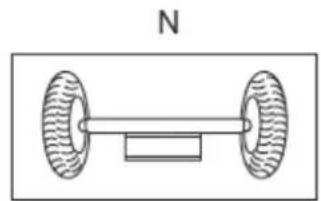
natural_image
Simple line drawing of a dumbbell with two wheels and a rectangular block, labeled 'N' above (no text or symbols on the diagram itself)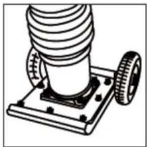
natural_image
Technical line drawing of a mechanical assembly with coiled spring and two wheels (no text or symbols)HINWEIS
natural_image
Symbol of a waste bin with crossed lines indicating no waste, and a solid black rectangle below (no text or labels)This manual contains important information and advice for the correct and safe use and maintenance of the ZI-RAM80C.
Following the usual commercial name of the machine (see cover) is substituted in this manual with the name "machine".
The manual is part of the machine and may not be stored separately. Read it profoundly before first use of the machine and keep it for later reference. When the machine is handed to other persons always put the manual to the machine.
Please follow the security instructions!

Please read the entire manual, to prevent misunderstandings, machine damage or even injuries!
Due to continuous development of our products illustrations, pictures might differ slightly.
If you however find errors in this manual, please inform us.
Technical changes expected!
Copyright law
© 2017
This manual is protected by copyright law – all rights reserved. Especially the reprinting as well as the translation and depiction of pictures will be prosecuted by law. Court of jurisdiction is the Landesgericht Linz or the competent court for 4707 Schlüsslberg, AUSTRIA.
Customer Support
11.1 Application field
The ZIPPER vibrating tamper ZI-RAM80C has to be used solely for following operations under compliance to all operations, security and maintenance guidelines described in this manual and furthermore all general security and work safety guidelines:
Earth work
Foundation trench tamping
Pavement and street works
Any other use is deemed to be a case of misuse. The user/operator and not the manufacturer will be held liable for damage and/or injuries of any kind that result from such misuse.
To use the machine properly you must also observe the safety regulations, the assembly instructions and the operating instructions to be found in this manual.
All persons who use and service the machine have to be acquainted with this manual and must be informed about the machine's potential hazards.
It is also imperative to observe the accident prevention regulations in force in your area.
The same applies for the general rules of occupational health and safety.
The manufacturer shall not be liable for any changes made to the machine nor for any damage resulting from such changes.
11.2 Safety instructions
- Do not operate the machine at insufficient lighting conditions.
- Do not operate the machine indoors.
- Do not operate the machine when you are tired, when your concentration is impaired, and/or you are under the influence of drugs, medication or alcohol.
• Always be focused when working, take care to maintain a safe posture at every time. - Do not use the tamping rammer on a slope steeper than 15^ .
- Do not work on slippery ground. The operation of the machine on icy or snowy ground is forbidden! Slipping/ stumbling/ falling down is a frequent cause of severe injuries.
- Beware of machine tumbling, it may cause severe injuries!
- The machine shall be used only by trained persons.
• Non authorized persons, especially children, shall be kept away from the work area. - Do not wear loose clothing, long hair openly or loose jewellery like
- necklaces etc. when operating the machine
• They might be caught by machine parts and cause serious injuries. - Use proper safety clothing and devices when operating the machine (safety gloves, safety goggles, ear protectors, safety shoes ...)!
- Combustion engines produce toxic emissions which are harmful to your health. Being exposed to the emissions in a closed room will lead to unconsciousness and death! Therefore never let the machine running in closed areas.
- During refueling open light, fire or smoking is forbidden.
- Don't refuel when the engine's running or some components are still hot.
- Only refuel outdoors or in good ventilated rooms.
• Always wipe off spilt fuel immediately. - Fuel is highly flammable!
- Burning Hazard! During working hot exhaust gases escape and some parts like the engine and muffler are getting very hot.
- Never leave the machine running unattended! Before leaving the working area switch the machine off and wait until the machine stops.
- Switch off the machine before maintenance or adjustment.
- Storage always with an empty tank in a safe place.
11.3 Remaining and particular risks
Even when the machine is used as prescribed the operation of a tamping rammer incorporates some risks that cannot be eliminated entirely:
Crush injuries
Keep hands and especially your feet away from the compacting plate! Always work concentrated and keep your safe balance at all times.
When working with the ZI RAM80C tamping rammer your are OBLIGED TO WEAR SAFETY SHOES WITH STEEL CAPS.
Adverse health effects through vibration
A long, continuous use, or a regular use of the tamping rammer by one person may influence your health: blood circulatory disturbances (especially of your hands), joint damages are possible.
Therefore:
■ Make breaks regularly
- Wear well cushioned gloves to reduce vibration intensity.
- The hardness of the underground, genetical predisposition for blood circulatory disturbances and low temperature reduce the length of the operation times not being hazardous to your health!
Excessively long operation sessions, and the regular operation may cause damages of the joint and muscular system of your body. Adjust operation times in accordance with your state of physical well-being.
Potential hazards of the working environment
When working in foundation trenches, make sure that the trench walls are stable and not vulnerable to collapse under the effect of vibration.
Assure yourself that the operated underground does not contain power leading electro cables, gas or water pipes which might be damaged through the vibration.
Take especial care when operating the machine near unsecured borings or construction pits. The operation of the machine regarding work place environment is upon the users judgement and liability.
Burn Hazard
Touching the muffler, the exhaust pipe, the spark plug assembly and the motor assembly during operation can lead to severe hand burns!
Hazard of hearing disorders
Continuously high noise levels lead to hearing disorders. Always wear a certified hearing protection.
Special safety clothing
When working with hot bitumen material you are obliged to wear special safety trousers!
12 SETUP
NOTICE
Check the compactor plate, the air inlet, the muffler and the air filter condition.
Clean them if necessary with a mild solvent.
Do not use paint thinners, petrol or other aggressive chemicals or abrasives for cleaning – they damage the machine.
12.1 Checks and tasks before first operation
Read, understand, and follow security and setup information
Check all fixing nuts and screws of the machine if tightened well! Not entirely tightened nuts and screws might become even looser and be lost due to the vibration during operation
ATTENTION!

A too low oil level leads to engine damages.
Please understand that we do not accept any reclamations on engine damage being caused by insufficient oil level.
The handling costs of claimed guarantee of defect engines that during service check turn out to be caused by an insufficient oil level will be charged to the customer entirely.
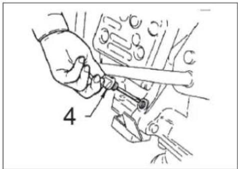
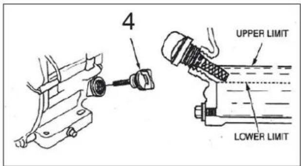
12.1.1 Check motor oil!
Oil capacity: 0,6 litre
Oil type: SF 15W-40
- To check the engine oil level, place the rammer after 10 minutes with the engine off on secure, level ground.
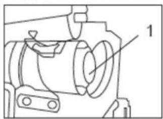
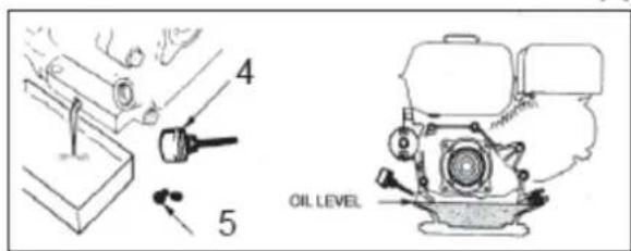
- The filter cap / dipstick from the oil filler neck (4) Remove and wipe clean.
- Insert the dipstick into the oil tank, but without tighten the screw and then remove it again. Check the oil level on the dipstick.
- If the oil lever is to low top up the oil SF 15W40 to the edge of the oil filler neck.
natural_image
Hand holding a wrench inside a mechanical component, no visible text or symbols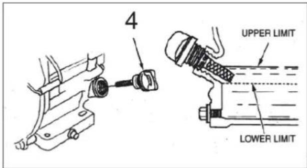
12.1.2 Check tamper oil
Oil capacity: 0,8 litre
Oil type: SF 15W-40
- To check the engine oil level, place the rammer after 10 minutes with the engine off on secure, level ground
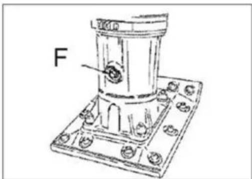
- Clean pollution in the area of the sight glass (F).
- Check the oil level on sight glass (F). The oil level is OK if the sight glass is full or 34 full.
If no oil is visible oil must be supplied.
- Tilt the tamper until the roll off bar (I) is on the ground.
- Loosen the oil screw (F).
- Fill in oil
- Thiqten the oil screw
■ Place tamper in upright position
natural_image
Technical line drawing of a mechanical component with mounting flanges and a labeled feature 'F' (no text or symbols beyond label)12.1.3 Check fuel level
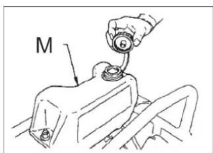
Fuel capacity: 2,7 litre
Fuel type: ROZ 95
■ The ZI-RAM80C is being powered with petrol (min. octane 95)
- Pay attention to all security regulations in connection with fuel.
■ Remove fuel tank cap, check fuel level by sight.
- If refueling is necessary, pay attention to all security regulations regarding refueling, refuel only with filter.
■ Refueling only with filter.

13 OPERATION
- Secure the working area properly before you start to compact.
- Never attempt to put the machine into service without having read the security, setup and operation instruction in this manual and having performed all necessary checks and tasks described in the chapter before.
- The correct level of humidity is decisive for good compacting results. Humidity is a kind of lubrication helping to compress particles more together.
Compacting an underground without any humidity is not possible. Too high levels of humidity make compacting ineffective as well and might cause the machine to stall.
- Do not use the tamping rammer at hard undergrounds, frozen underground or rocky underground.
13.1 Start and stop
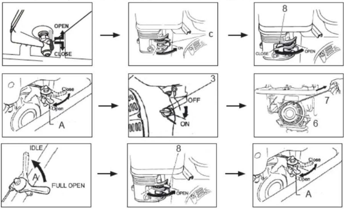
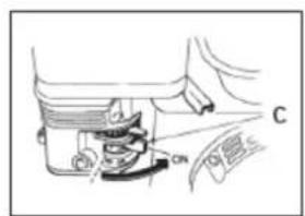
13.1.1 Cold start
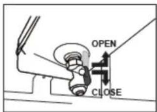
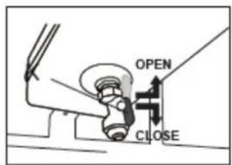
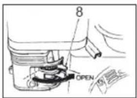
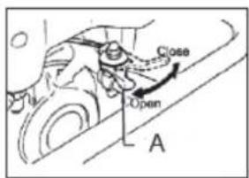
- Open fuel cock (K) and (c) entirely
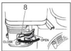
- Set Choke lever (8) to „CLOSE“
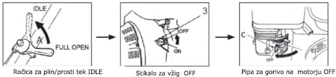
- Bring throttle lever (A) into middle speed position (middle position)
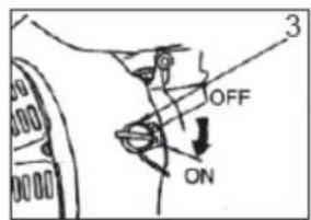
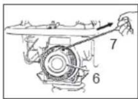
■ Main switch (3) ON - Recoil start: Grip the handle (7) of the recoil starter, pull it back slightly until you feel resistance, let it roll back, pull it out briskly in one pull entirely.
- When the engine started, open the choke (8), adjust throttle (A) in order that the engine runs idle. Let the engine run in idle for at least some minutes.
- To start to compact bring the throttle lever (A) cautious into max. speed position!
flowchart
graph TD
    A["OPEN CLOSE"] --> B["ON"]
    B --> C["CLOSE"]
    C --> D["OPEN"]
    E["Close Open"] --> F["OFF ON"]
    F --> G["3"]
    G --> H["7"]
    H --> I["6"]
    I --> J["FULL OPEN"]
    K["IDLE"] --> L["FULL OPEN"]
    L --> M["OPEN"]
    M --> N["8"]
    N --> O["Open"]
    O --> P["A"]
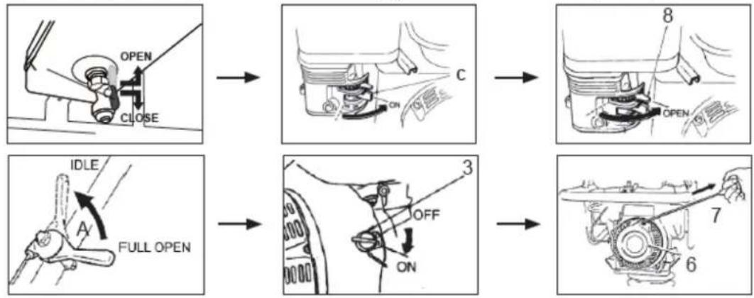
13.1.2 Warm start
- Open fuel cock (K) and (c) entirely
- Set Choke lever (8) to „OPEN“
■ Bring throttle lever (A) into idle speed position
■ Main switch (3) ON
- Recoil start: Grip the handle (7) of the recoil starter, pull it back slightly until you feel resistance, let it roll back, pull it out briskly in one pull entirely.
- To start to compact bring the throttle lever (A) cautious into max. speed position!
flowchart
graph TD
    A["OPEN CLOSE"] --> B["Car Engine"]
    B --> C["Open"]
    D["IDLE FULL OPEN"] --> E["Car Engine"]
    E --> F["OFF ON"]
    G["8"] --> H["Engine"]
    H --> I["Open"]
    J["3"] --> K["Car Engine"]
    K --> L["Off"]
    M["6"] --> N["Engine"]
ACHTUNG!

Open the choke only when the throttle is at idle otherwise the rammer can start moving.
On first use or for motors that were not used since long time perhaps is to pull the starter rope several times so that fuel reaches the carburetor.
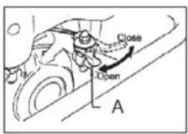
13.1.3 Stop the machine
- Bring throttle lever (A) into idle speed position
■ Main switch (3) OFF - Close the fuel cock (K) and (c) entirely.
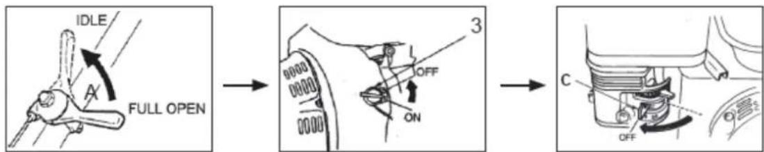
NOTE

A sudden switch off the engine at full throttle can cause engine damage.
13.2 Proper using
Keep the tamper clean and dry.
Prevent blank hits.
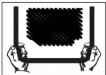
When pushing away the material or when lifting the tamper, let this in no case run with full throttle. For optimal control guide bracket as shown.
If the tamper tilts on its side, then lie down as shown and immediately stop the engine (main switch (3) to "OFF")
natural_image
Illustration of two hands holding a large rectangular frame with a textured black pattern on the top (no text or symbols)
natural_image
Technical line drawing of a mechanical device with internal components and spring assembly (no text or symbols)NOTE
To prevent engine damage the tamper should not continue run if he is on the side.
13.2.1 Compacting
- Open throttle lever (A) for max. power
- Grip the guide bracket with both hands and lead the tamper. Releases in no case the guide bracken when you are compacting.
- Let the tamper move forward itself. Do not apply pressure to the tamper. NEVER try to move the machine with muscle power forward.
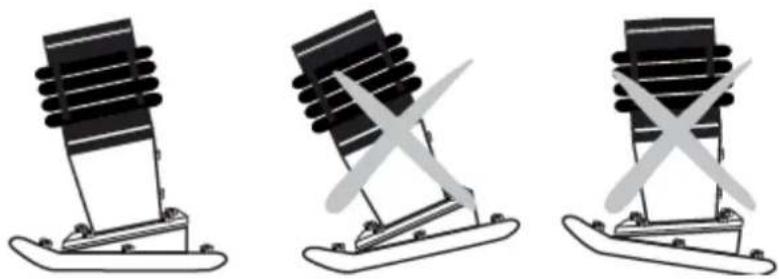
- The tamping foot must always occur in a parallel position to the ground (d) to avoid extreme wear on the drive.
- A ground with too much moisture can reduce a good compression. Let dry the ground before compaction something.
- A very dry ground swirls when working with the tamper much dust. By adding moisture the compression can be improved and the maintenance of the air filter can be reduced.
natural_image
Three identical diagrams of a mechanical device with a central blade and two cross-shaped blades, shown side by side (no text or symbols)NOTE
The tamper does not apply to concrete or hard or compacted surfaces. In such cases the device will jump rather than vibrate causing damage to the tamping foot and motor.
14 MAINTENANCE
ATTENTI ON

Do not perform any checks, Cleaning or maintenance and do not refuel oil or fuel when machine is running!
Therefore: Shut the machine down and let it cool down beforehand
The machine requires hardly any maintenance. Let malfunctions and machine damages be repaired immediately by trained persons.
14.1 Maintenance schedule
| Checks and maintenance | |
| Check fuel | Before every operation |
| Check for loose or lost screws, bolts. | Before every operation |
| Damage of any machine part | Before every operation |
| Check for oil or fuel spill under the machine = leak | Before every operation |
| Check /refill motor oil | Before every operation |
| Clean machine, especially compactor bottom side | After every operation |
| Clean air filter | Every 100 working hours/ monthly |
| Check / clean spark plug | Every 50 working hours / monthly |
| Change motor oil (SF15W40) | After first 20 hours of operationLater every 200 hours of operation / quarter-yearly |
| Change Tamper oil (SF15W40) | After first 20 hours of operationLater every 200 hours of operation / quarter-yearly |
14.2 Change engine oil
- Change engine oil after the first 20 hours of operation.
■ Later change it every 200 hours - Best time for engine oil change is approx. 15 minutes after a longer operation, the oil should be lube warm then.
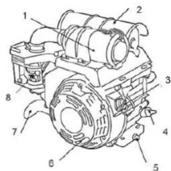
- To drain the old oil, first unfasten the oil drain plug (5) and oil filler dipstick (4) at the bottom side of the engine assembly.
- When draining the old oil, catch it in a bin.
■ Fill in the new engine oil
ATTENTION!
Dispose of the old oil in an environmentally friendly way!
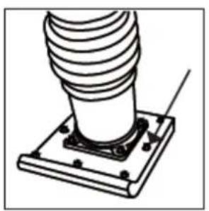
Clean air filter
A polluted air filter makes it very hard to start the engine, it impairs the engine output and leads to engine malfunctions.
It shortens the engines lifespan and in extreme cases it can ruin the engine within short time.
So take care to have your air filter kept clean at every time!
To clean the air filter, unfasten the wing nut, remove the air filter cap, remove the froth mantle and the air filter.
Clean both mechanically (with a brush).
natural_image
Technical line drawing of a mechanical assembly with labeled component (no text or symbols present)Wipe both thoroughly with a solvent composed of 3 parts diesel and one part motor oil. Drain motor oil onto the filter, remove excessive motor oil by wringing it out.
NOTE
Let the engine never run without or with a damaged air filter. Dirt gets so into the engine and can causing severe engine damage. In this case retailers and manufacturers dissociate from any warranty.
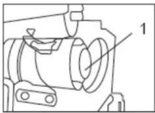
14.3 Clean spark plug
Remove the spark plug and clean it with a brush from debris. The contact should be 0,6-0,8mm.
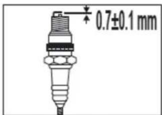
Zündkerze prüfen
14.4 Transport
ACHTU NG

ALWAYS shutdown engine before transporting.
Tighten fuel tank cap securely and close fuel cock to prevent fuel from spilling.
Drain fuel when transporting rammer over long distances or bad roads.
When placing the rammer inside a truck-bed for transport, always tie-down the rammer
If possible always transport the tamper in an upright position. However it is important to ensure that the unit may not fall over. If this is impossible lie the tamper and lashed firmly to prevent rolling or moving.
- Always turn off the engine when transporting
- Close fuel cock (K) and (c) to prevent fuel leaks
■ Empty the fuel tank if the transport way is very long - To lift the tamper use always the transport hanger (J)
14.4.1 Transport wheels
The transport wheels facilitate the transport over short distances.
- Turn off the engine.
- Tilt the tamper forward and slide the axis of the wheels (N) into its holder.
- Secure the axis with the foot, tilt the tamper back on the axle and proceed using the guide bracket.
- To remove the transport wheel proceed in reverse order
natural_image
Technical line drawing of a mechanical assembly with threaded component and mounting base (no text or symbols)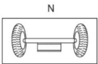
natural_image
Simple line drawing of a dumbbell with two wheels and a rectangular base, labeled 'N' at the top (no text or symbols on the diagram itself)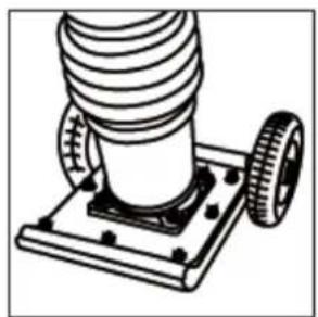
natural_image
Technical illustration of a mechanical assembly with coiled spring and two wheels (no text or symbols)NOTE
The unit is heavy and may not be lifted by a single person. Using only with 2 persons. Use the transport wheels only on firm, level ground and for short distances. The transport wheels must be removed before the next compacting..
14.5 Storage
If you store the tamping rammer for longer than 30 days:
- Drain fuel from fuel tank, fuel pipe.
- Remove spark plug, drip some drops of oil into the plug hole into the cylinder housing. Fasten the spark plug back again and push the recoil starter (Attention Main switch off) with the effect that the engine cock moves up and down and the oil gets distributed along the combustion chamber walls.
- Cover the tamping rammer with a clean cloth and store it in a clean and dry place.
14.6 Disposal
DO NOT DISPOSE your ZI-RAM80C in residual waste. Contact your local authorities about the available disposal possibilities. Drain the remaining petrol, motor oil and gear oil before disposing the machine and dispose these separately in an environmentally sound way. A non proper disposal of the machine can lead to contamination of soil and water which in turn will affect you in the long run as it gets through soil and water into the food chain.

natural_image
Symbol of a trash bin crossed with a diagonal line and a horizontal bar below (no text or labels)15 TROUBLE SHOOTING
| problem | Reason /solution |
| If the engine does not start: | Check the ON/OFF switch if it is „ON”Check the fuel cock if onCheck for fuel, check the fuel pipe for leaksCold start / warm start differenceSpark plug polluted, contacts defectCarburator or air filter polluted. |
| If the engine does not stop: | Check fuel supply chain.Check motor oil level.Check air filter. |
| When engine output drops: | Check the air filter.Check fuel supply chain for damages/leaks |
| If the machine does not work freely: | Check bottom side of compactor plate for built up compacted debris. |
16 PŘEDMLUVA (CZ)
Vážený zákazníku!
natural_image
Hand holding a wrench inside a mechanical component, no visible text or symbolsnatural_image
Technical line drawing of a mechanical component with mounting flanges and a labeled feature 'F' (no text or symbols beyond label)natural_image
Illustration of two hands holding a container with a dark rectangular frame, no text or symbols present.
natural_image
Technical line drawing of a mechanical assembly with springs and housing (no text or symbols)VÝSTRAHA
natural_image
Mechanical lever diagram with a black spring and base, labeled 'd' (no text or symbols on the lever itself)
natural_image
Illustration of a mechanical press or stand with a black block and two white blades (no text or symbols)
natural_image
Simple line drawing of a mechanical component with intersecting X-shaped marks (no text or symbols)VÝSTRAHA
natural_image
Technical line drawing of a mechanical assembly with threaded component and mounting base (no text or symbols)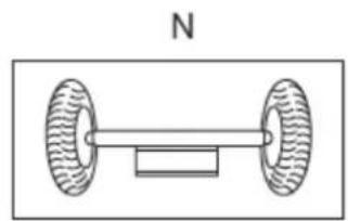
natural_image
Simple line drawing of a dumbbell with two wheels and a central shaft, labeled 'N' (no text or symbols on the diagram itself)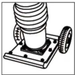
natural_image
Technical line drawing of a mechanical component with threaded base and wheels (no text or symbols)VÝSTRAHA
natural_image
Line drawing of a hand using a wrench to adjust or install a mechanical component (no text or symbols present)
24.1.2 Check tamper oil
natural_image
Technical line drawing of a mechanical component with mounting flange and bolted base (no text or symbols)POZOR!

VÝSTRAHA

natural_image
Illustration of two hands holding a rectangular frame with a textured black pattern on the top (no text or symbols)
natural_image
Technical line drawing of a mechanical assembly with springs and housing (no text or symbols)VÝSTRAHA
natural_image
Three identical diagrams of a mechanical device with a spring-like base, showing cross-shaped cutouts and mounting brackets (no text or symbols)VÝSTRAHA
natural_image
Technical line drawing of a mechanical component with mounting flange and bolt holes (no text or symbols)Stampffuß wechseln
26.5 Čistenie vzduchového filtra
natural_image
Technical line drawing of a mechanical assembly with threaded component and mounting base (no text or symbols)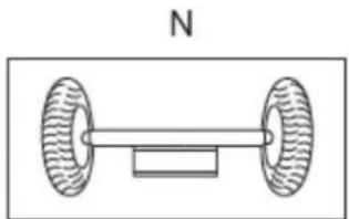
natural_image
Simple line drawing of a two-wheeled vehicle with a central shaft and wheels, labeled 'N' (no text or symbols on the diagram itself)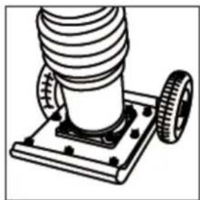
natural_image
Technical line drawing of a mechanical assembly with a coiled spring and two wheels (no text or symbols)VÝSTRAHA
27 UVOD (SL)
Spoštovani kupec!
natural_image
Line drawing of a hand holding a tool with a pen, no text or symbols present
Kontrola olja nabijalnika
natural_image
Technical line drawing of a mechanical component with mounting flange and bolted base (no text or symbols)29.1.2 Kontrola goriva
Količina polnjenja goriva: 2,7 litra
Gorivo: ROZ 95


Zaganjalnik z vrvico

Ročica za plin OPEN
Izklapljanje
- Ročico za plin (A) potisnite v desno, v prosti tek.
- Stikalo za vžig (3) dajte v položaj „OFF / IZKLOPLJENO“.
- Nato zaprite pipo za gorivo na motorju (c) tako, da jo potisnete v levo.
- Pipo za gorivo (K) na rezervoarju za gorivo (spodaj) zaprete tako, da jo obračate navzdol.
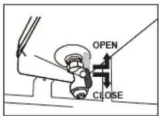
Pipa za gorivo na rezervoarju CLOSE
NAPOTEK
natural_image
Illustration of two hands holding a large rectangular frame with a hatched pattern on the top (no text or symbols)
natural_image
Technical line drawing of a mechanical assembly with springs and housing (no text or symbols)NAPOTEK
natural_image
Three diagrams showing a mechanical device with a spring-like structure, crossed by a tool, and a cross symbol (no text or labels)NAPOTEK
natural_image
Technical line drawing of a mechanical component with mounting flange and bolt holes (no text or symbols)natural_image
Technical line drawing of a mechanical component with labeled parts (no readable text or symbols)natural_image
Technical line drawing of a mechanical assembly with threaded component and mounting base (no text or symbols)
natural_image
Simple line drawing of a dumbbell with two wheels and a central shaft, labeled 'N' (no text or symbols on the diagram itself)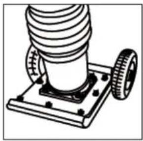
natural_image
Technical line drawing of a mechanical assembly with a coiled spring and two wheels (no text or symbols)NAPOTEK
natural_image
Line drawing of a hand using a wrench to adjust mechanical parts (no text or symbols)Zaporni vijak za ulje

Razina ulja
natural_image
Technical line drawing of a mechanical component with mounting base and labeled part 'F' (no text or symbols beyond label)Kontrolno staklo / vijak za ispuštanie ulia Schauglas / Olablassschraube
35.1.3 Provjera goriva
Ručica gasa 'OPEN'
PAŽNJA!
natural_image
Illustration of two hands holding a large rectangular frame with a textured black pattern inside (no text or symbols)
natural_image
Technical line drawing of a mechanical device with springs and housing (no text or symbols)NAPOMENA
natural_image
Three identical diagrams of a mechanical device with a spring-like base, showing cross-shaped cutouts and mounting base (no text or symbols)NAPOMENA
natural_image
Technical line drawing of a mechanical component with mounting flange and bolt holes (no text or symbols)natural_image
Technical line drawing of a mechanical assembly with labeled component (no text or symbols present)natural_image
Technical line drawing of a mechanical assembly with threaded component and mounting base (no text or symbols)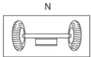
natural_image
Simple line drawing of a dumbbell with two wheels and a central bar, labeled 'N' (no text or symbols on the diagram itself)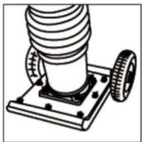
natural_image
Technical line drawing of a mechanical assembly with a coiled spring and two wheels (no text or symbols)NAPOMENA
Uređaj je težak i ne smije ga podizati samo jedna osoba. Osigurajte i 2. osobu. Transportne kotače koristite samo na ravnoj i čvrstoj podlozi i za male udaljenosti. Transportne kotače treba ukloniti prije sljedećeg nabijanja.
37.8 Skladištenje
Duže od 30 dana:
natural_image
Symbol of a waste bin with crossed lines indicating no waste, and a solid black rectangle below (no text or labels)Stručno zbrinjavanje: Stroj demontirajte koliko možete te pojedine dijelove odvezite na zbrinjavanje. Gorivo i motorno ulje potpuno ispustite i jednako tako stručno zbrinite!
38 UKLANJANJE POGREŠAKA
natural_image
Line drawing of a hand using a wrench to adjust mechanical parts (no text or symbols)Olajelzáró csavar
Olajszint
natural_image
Technical line drawing of a mechanical component with mounting flange and bolted base (no text or symbols)natural_image
Illustration of two hands holding a large rectangular frame with a textured black pattern on the top (no text or symbols)
natural_image
Technical line drawing of a mechanical assembly with springs and housing (no text or symbols)ÉRTESÍTÉS
natural_image
Three diagrams showing a mechanical device with a spring-loaded base, marked with X symbols indicating force or movement (no text or labels present)ÉRTESÍTÉS
natural_image
Technical line drawing of a mechanical component with mounting flange and bolt holes (no text or symbols)natural_image
Technical line drawing of a mechanical assembly with labeled component (no text or symbols present)natural_image
Technical illustration of a mechanical assembly with threaded component and mounting base (no text or symbols)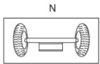
natural_image
Simple line drawing of a dumbbell with two wheels and a rectangular block, labeled 'N' above (no text or symbols on the diagram itself)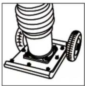
natural_image
Technical illustration of a mechanical assembly with threaded components and a base plate (no text or symbols)ÉRTESÍTÉS
(EN) With ZIPPER spare parts you use spare parts that are ideally matched to each other. The fitting accuracy of the parts shortens their installation time and increases the service life of the machine.
NO TE
The installation of parts other than original spare parts leads to the loss of the
guarantee! Therefore, when replacing components/parts, only use original spare parts! When ordering spare parts, please use the service form at the end of this manual. Always state machine type, spare part number and designation. In order to avoid misunderstandings, we recommend enclosing a copy of the spare part drawing with the spare part order, on which the required spare parts are clearly marked.
You will find the ordering address under customer service addresses in the foreword to this documentation.
| PART NO. | DESCRIPTION | Quantity |
| 1 | Sunk head bolt 12*70H | 4 |
| 2 | Sunk head bolt 12*55 H | 7 |
| 3 | Metal sheet | 1 |
| 4 | Foot 285B-331L | 1 |
| 5 | Foot Assy | 1 |
| 6 | Washer SWφ12 | 11 |
| 8 | Washer SWφ12 | 7 |
| 9 | Nylon nut M12 | 11 |
| 10 | Nut M18, | 1 |
| 11 | Socket head bolt 10*20T | 4 |
| 12 | Socket head bolt 10*35T | 4 |
| 13 | Foot plate | 1 |
| 14 | Packing 1/4(CU) | 1 |
| 15 | Plug M12*1.25 | 1 |
| 19 | O-ring G-90 | 1 |
| 20 | Inner spring | 2 |
| 21 | Out spring | 2 |
| 22 | Spring cylinder | 1 |
| 24 | Pin φ16 | 1 |
| 25 | Piston rod kit | 1 |
| 26 | Stop ring φ15 | 1 |
| 27 | O-ring G-90 | 2 |
| 28 | Protection sleeve | 1 |
| 28 | Protection sleeve (Optional) | 1 |
| 29 | Copper packing 17*25.5*1 | 1 |
| 30 | Level gauge, plug type | 1 |
| 31 | Packing 1/4(CU) | 1 |
| 32 | Plug M12*1.25 | 1 |
| 33 | O-ring 160*4 | 1 |
| 34 | Bellows clamp | 2 |
| 35 | Band guide,bellows | 2 |
| 36 | Socket head bolt M6*50 | 2 |
| 37 | Nut M6 | 2 |
| 38 | Dowel pinφ6×8 | 1 |
| 39 | Bellow | 1 |
| 39 | Bellow (Optional) | 1 |
| 41 | Pin 6D-8.5L | |
| 43 | Socket head bolt 10*35T | 4 |
| 44 | Guide cylinder | 1 |
| 45 | O-ring φ110×4 | 1 |
| 46 | piston end | 1 |
| 47 | Wheel (Optional ) | 2 |
| 48 | bracket of trolley | 1 |
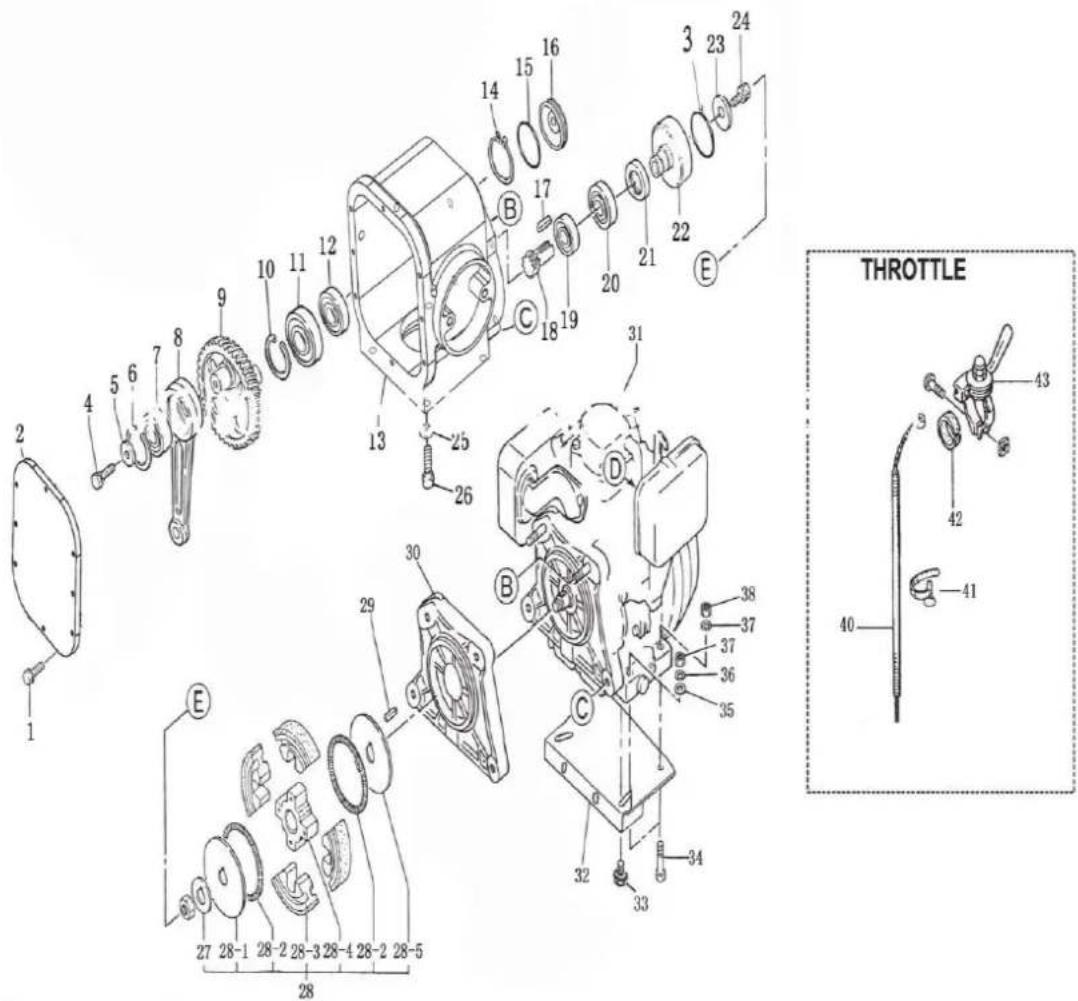
| PART NO. | DESCRIPTION | Quantity | PART NO. | DESCRIPTION | Quantity |
| 1 | Bolt 6*18H,SW | 9 | 21 | Oil seal 40*68*8 | 1 |
| 2 | Case cover | 1 | 22 | Clutch drum | 1 |
| 3 | O-ring 22.4*2.65 | 1 | 23 | Washer 8*7 | 1 |
| 4 | Hexagonal bolt 8*20 | 1 | 24 | Bolt M 8*25 T | 1 |
| 5 | Washer M8 | 1 | 25 | Washer SW 10 | 4 |
| 6 | Internal circlip 50 | 1 | 26 | Socket head bolt 10*35 | 4 |
| 7 | Bearing6204 | 1 | 27 | Lock washer | 1 |
| 8 | Connecting rod | 1 | 28 | Clutch assy | 1 |
| 9 | Gear wheel | 1 | 29 | Woodruff key 4*13 | 1 |
| 10 | Internal circlip 62 | 1 | 30 | Connecting plate, | 1 |
| 11 | Bearing6207 | 1 | 31 | Engine | 1 |
| 12 | Bearing6305-2Z | 1 | 32 | Bottom plate, engine | 1 |
| 13 | Crank case | 1 | 33 | Bolt M10*50 | 2 |
| 14 | External circlip 20 | 1 | 34 | Bolt M8*40 | 4 |
| 15 | O-ring 40*2.4 | 1 | 35 | Washer, SW M8 | 4 |
| 16 | Bearing cover | 1 | 36 | Washer,8.5*22*3 | 4 |
| 17 | Key 5*20 | 1 | 37 | Nylon nut M8 | 4 |
| 18 | Pinion | 1 | 40 | Throttle wire | 1 |
| 19 | Bearing6204 | 1 | 43 | Throttle lever | 1 |
| 20 | Bearing6007 | 1 |
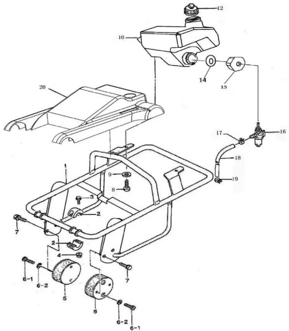
| PART NO. | DESCRIPTION | Quantity | PART NO. | DESCRIPTION | Quantity |
| 1 | Handle | 1 | 10 | Fuel tank | 1 |
| 2 | Roller handle | 2 | 12 | Fueltank cap | 1 |
| 3 | Flange bolt 8*25 H | 4 | 14 | ptfe washer ¢18 | 1 |
| 4 | Flange nut M5 | 4 | 15 | Lower cover | 1 |
| 5 | Shock absorber | 2 | 16 | Fuel cock assy | 1 |
| 6-1 | Shock head bolt 10*20 | 4 | 17 | Hose band 9.5D | 2 |
| 6-2 | Tooth locked washer BM10 | 8 | 18 | Hose, fuel | 1 |
| 7 | Bolt10*20 T | 4 | 19 | Hose band 9.5D | 2 |
| 8 | Hexagonal bolt 6*20 | 2 | 20 | Cover | 1 |
| 9 | Gasket φ8 | 2 |
Company ZIPPER Maschinen GmbH grants for mechanical and electrical components a warranty period of 2 years for amateur use; and warranty period of 1 year for professional use, starting with the purchase of the final consumer. In case of defects during this period, which are not excluded by paragraph 3, ZIPPER will repair or replace the machine at its own discretion.
2.) Report:
In order to check the legitimacy of warranty claims, the final consumer must contact his dealer. The dealer has to report in written form the occurred defect to ZIPPER. If the warranty claim is legitimate, ZIPPER will pick up the defective machine from the dealer. Returned shippings by dealers which have not been coordinated with ZIPPER, will not be accepted and refused.
3.) Regulations:
a) Warranty claims will only be accepted, when a copy of the original invoice or cash voucher from the trading partner of ZIPPER is enclosed to the machine. The warranty claim expires if the accessories belonging to the machine are missing.
b) The warranty does not include free checking, maintenance, inspection or service works on the machine. Defects due to incorrect usage of the final consumer or his dealer will not be accepted as warranty claims either. Some examples: usage of wrong fuel, frost damages in water tanks, leaving fuel in the tank during the winter, etc.
c) Defects on wear parts are excluded, e.g. carbon brushes, collection bags, knives, cylinders, cutting blades, clutches, sealings, wheels, saw blades, splitting crosses, riving knives, riving knife extensions, hydraulic oils, oil/air/fuel filters, chains, spark plugs, sliding blocks, etc.
d) Also excluded are damages on the machine caused by incorrect or inappropriate usage, if it was used for a purpose which the machine is not supposed to, ignoring the user manual, force majeure, repairs or technical manipulations by not authorized workshops or by the customer himself, usage of non-original ZIPPER spare parts or accessories.
e) After inspection by our qualified personnel, resulted costs (like freight charges) and expenses for not legitimated warranty claims will be charged to the final customer or dealer.
f) In case of defective machines outside the warranty period, we will only repair after advance payment or dealer's invoice according to the cost estimate (incl. freight costs) of ZIPPER.
g) Warranty claims can only be granted for customers of an authorized ZIPPER dealer who directly purchased the machine from ZIPPER. These claims are not transferable in case of multiple sales of the machine.
4.) Claims for compensation and other liabilities:
The liability of company ZIPPER is limited to the value of goods in all cases. Claims for compensation because of poor performance, lacks, damages or loss of earnings due to defects during the warranty period will not be accepted. ZIPPER insists on its right to subsequent improvement of the machine.
49 ZÁRUKA (CZ)
1.) Záruka:
We monitor the quality of our delivered products in the frame of a Quality Management policy.
Your opinion is essential for further product development and product choice. Please let us know about your:
- Impressions and suggestions for improvement.
- experiences that may be useful for other users and for product design
- Experiences with malfunctions that occur in specific operation modes
We would like to ask you to note down your experiences and observations and send them to us via FAX, E-Mail or by post
Erworben von / purchased from:
E-Mail/ e-mail:
Please describe amongst others in the problem: What has cause the problem/defect, what was the last activity before you noticed the problem/defect? For electrical problems: Have you had checked you electric supply and the machine already by a certified electrician?
3. Bitte beachten
/ Additional information
INCOMPLETELY FILLED SERVICE FORMS CANNOT BE PROCESSED! FOR GUARANTEE CLAIMS PLEASE ADD A COPY OF YOUR ORIGINAL SALES / DELIVERY RECEIPT OTHERWISE IT CANNOT BE ACCEPTED. FOR SPARE PART ORDERS PLEASE ADD TO THIS SERVICE FORM A COPY OF THE RESPECTIVE EXPLODED DRAWING WITH THE REQUIRED SPARE PARTS BEING MARKED CLEARLY AND UNMISTAKABLE. THIS HELPS US TO IDENTIFY THE REQUIRED SPARE PARTS FASTLY AND ACCEL- LERATES THE HANDLING OF YOUR INQUIRY.