
ZI-RPE125 - Uncategorized Zipper - Free user manual and instructions
Find the device manual for free ZI-RPE125 Zipper in PDF.

| Product Type | Power Planer |
| Brand | Zipper |
| Model | ZI-RPE125 |
| Dimensions (approx.) | 300 x 150 x 180 mm |
| Weight (approx.) | 3.5 kg |
| Power Supply | 230 V ~ 50 Hz, 1200 W |
| No-Load Speed | 16000 min⁻¹ |
| Planing Width | 82 mm |
| Planing Depth | 0 - 2.0 mm |
| Main Functions | Planing, rebating, beveling, chamfering |
| Maintenance | Clean after use, lubricate bearings, replace carbon brushes when worn |
| Safety Features | Double insulation, lock-off switch, chip guard, anti-kickback clutch |
| Spare Parts Available | Blades, carbon brushes, belt, drive gear, switch |
| Reparability | Design allows for replacement of wear parts; professional service recommended for motor |
| Included Accessories | Parallel guide, blade set, wrench, dust bag |
| General Information | For woodworking only; use with proper hearing and eye protection |
Frequently Asked Questions - ZI-RPE125 Zipper
User questions about ZI-RPE125 Zipper
0 question about this device. Answer the ones you know or ask your own.
Ask a new question about this device
Download the instructions for your Uncategorized in PDF format for free! Find your manual ZI-RPE125 - Zipper and take your electronic device back in hand. On this page are published all the documents necessary for the use of your device. ZI-RPE125 by Zipper.
USER MANUAL ZI-RPE125 Zipper
natural_image
Green ZIPPER industrial machine with black frame and control panel (no visible text or symbols)ZI-RPE125
EAN: 9120039234137
CE
Engine don't start with low oil!!
1 INHALT/ INDEX
1 INHALT/ INDEX 2
14.1 Intended use of the machine....21
14.1.1 Technical Restrictions 21
14.1.2 Prohibited Use / Forseeable Misuse.... 21
14.2 User Qualification 21
14.3 Safety instructions 22
14.4 Special safety instructions for the operation of ZI-RPE125 22
14.5 Safety instructions for machines with combustion engine.... 22
14.6 Hazard warnings 23
15 ASSEMBLY 23
15.1 Check scope of delivery 23
15.2 Assembly 23
15.3 Checklist before each use 24
15.3.1 Checking the engine oil level 24
15.3.2 Checking the fuel tank level 24
16 OPERATION 25
16.1 Information on Initial Start-up 25
16.1.1 Test Run Initial Start-up 25
16.1.2 Notes on the first 20 operating hours.... 25
16.2 Operating Instructions 25
16.3 Starting the Machine 26
16.4 Stopping the Machine 27
16.4.1 Emergency Stop 27
16.4.2 Normal switch-off 27
16.5 Moving machine forward / backward 27
17 MAINTENANCE 27
17.1 Maintenance and Servicing PLAN 27
17.1.1 Table of Measures 27
17.2 Changing the exciter oil.... 28
17.3 Changing the engine oil 28
17.4 Cleaning the air filter....28
17.5 Checking and replacing V-belt and coupling 29
17.5.1 Checking the V-belt tension.... 29
17.5.2 Tensioning the V-Belt 29
17.5.3 Changing the V-belt.... 29
17.5.4 Checking the clutch 30
17.6 Cleaning the spark plug 30
18 TRANSPORT 30
18.1 Transport over shorter distances....30
18.2 Lifting and transporting with separate devices.... 30
19 STORAGE 30
20 RECYCLING 30
21 TROUBLESHOOTING 31
22 ERSATZTEILE / SPARE PARTS 31
| 1 | Tankdeckel/ fuel filler cap | 10 | Treibstofftank / fuel tank |
| 2 | Unterer Gashebel / Lower throttle | 11 | Oberer Gashebel / Upper throttle |
| 3 | Startseil-Abdeckung / Start rope cover | 12 | Vibationsplatte / vibrating plate |
| 4 | Anlassergriff / starter handle | 13 | Exzentervibrator / eccentric vibrator |
| 5 | Treibstoffventil / fuel valve | 14 | Keilriemen-Abdeckung / V-belt cover |
| 6 | Choke-Hebel / choke lever | 15 | Heberahmen / Lifting frame |
| 7 | Luftfilter / air filters | 16 | Motoröl-Ablassschraube / oil drain plug |
| 8 | Zündkerze / spark plug | 17 | Haltebügel / holding bracket |
| 9 | Auspuff / muffler | 18 | Richtungshebel / direction lever |
natural_image
Mechanical assembly component with highlighted yellow arrows and label 'S' (no readable text or symbols)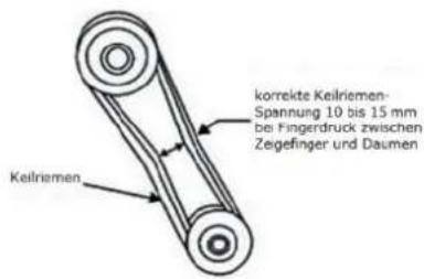
natural_image
Mechanical assembly component with labeled parts S and M, no readable text or symbols beyond labelsThis manual contains information and important instructions for the installation and correct use of the ZIPPER plate compactor ZI-RPE125.
Following the usual commercial name of the machine (see cover) is substituted in this manual with the name "machine".

This manual is part of the product and shall not be stored separately from the product. Save it for later reference and if you let other people use the product, add this instruction manual to the product.
Please read and obey the security instructions!
Due to constant advancements in product design, construction pictures and content may diverse slightly. However, if you discover any errors, inform us please.
Technical specifications are subject to changes!
Please check the product contents immediately after receipt for any eventual transport damage or missing parts.
Claims from transport damage or missing parts must be placed immediately after initial product receipt and unpacking before putting the product into operation.
Please understand that later claims cannot be accepted anymore.
Copyright
© 2018
This document is protected by international copyright law. Any unauthorized duplication, translation or use of pictures, illustrations or text of this manual will be pursued by law. Court of jurisdiction is the regional court Linz or the competent court for 4707 Schlüsslberg, Austria!
Customer service contact
This section contains information and important notices for safe commissioning and handling of machine.

For your own safety, read these operating instructions carefully before putting the machine into operation. This will enable you to handle the machine safely and prevent misunderstandings as well as possible damage to property and persons. Also observe the symbols and pictograms used as well as the safety instructions and hazard warnings!
14.1 Intended use of the machine
The machine is intended exclusively for the following activities:
For compacting (e.g. granular soils consisting of gravel and sand or mixtures of both) and for vibrating paving stones, bricks, etc. on small to medium-sized surfaces.
The rubber mat should only be used to vibrate paving stones, bricks and the like! Other materials such as gravel, chippings etc. must be processed without a rubber mat.
ZIPPER-MASCHINEN assumes no responsibility or warranty for any other use or use beyond this and for any resulting damage to property or injury.
14.1.1 Technical Restrictions
The machine is intended for use under the following ambient conditions:
Relative humidity: max. 65 %
Temperature (for operation) +5°C bis +40°C
Temperature (for storage and/or transport) -20^ C bis +55^ C
14.1.2 Prohibited Use / Forseeable Misuse
• Operation of the machine without adequate physical and mental aptitude
- Operating the machine without appropriate knowledge of the operating instructions (machine + motor).
• Changes in the design of the machine
- Operating the machine in wet and rainy conditions
- Operating the machine in a potentially explosive environment
- Operating the machine indoors or in closed areas
• Operation of the machine without functioning or missing guards
- Operation of the machine in hard soil, frozen soil and mixed soil containing fragments of bricks.
- Compaction of asphalt or sticky soils with a high clay content.
- Remove the safety markings attached to the machine.
- Modify, circumvent or disable the safety devices of the machine.
- Use of the machine for the transport of persons
The prohibited/hazardous use or disregard of the information and instructions presented in this manual will result in the voiding of all warranty and damage claims against Zipper Maschinen GmbH.
14.2 User Qualification
Prerequisite for the use / operation of the machine is a corresponding physical and mental aptitude as well as knowledge and understanding of the instruction Manual.
Please note that local laws and regulations may determine the minimum age of the operator and restrict the use of this machine!
Put on your personal protective equipment before working on the machine.
Work on electrical components or equipment may only be carried out by a qualified electrician or carried out under the guidance and supervision of a qualified Electrician.
14.3 Safety instructions
In order to avoid malfunctions, damage and health hazards when working with this machine, in addition to the general rules for safe working, the following measures in particular must be observed UNCONDITIONALLY:
- Check that the machine is in perfect condition before each use. Ensure that all guards are in place and working properly and that all nuts, bolts, etc. are securely tightened. Do not take the machine into operation if you notice that parts are missing or damaged!
- Ensure sufficient lighting conditions in the working and surrounding areas of the machine.
- Keep hands and feet away from moving machine parts and always ensure a safe stand when working.
- Ensure that the area to be tamped does not contain any electric cables, gas or water lines which could be damaged by vibration.
- Remove the adjustment tool from the machine before operation.
- Never leave the running machine unattended (always stop the machine before leaving it).
- Ensure that unauthorised persons maintain a safe distance from the machine and keep children away from the machine.
- The machine may only be operated, serviced or repaired by persons who are familiar with it and who have been informed of the dangers arising during this work.
- Always wear suitable personal protective equipment (ear protection, gloves, safety shoes, close-fitting protective clothing, etc.)!
- Do not work with the machine if you are tired, not concentrated or under the influence of medication, alcohol or drugs!
- Never operate the unit in the presence of flammable liquids or gases (danger of explosion!).
- Carry out maintenance, adjustment and cleaning work only when the engine is switched off.
- Only use spare parts and accessories recommended by Zipper machines.
14.4 Special safety instructions for the operation of ZI-RPE125
- The machine is designed to be operated by one person. Always operate the machine from behind. Never stand next to or in front of the machine when the engine is running.
- Longer continuous use of the vibratory plate can lead to circulatory disturbances, especially of the hands, caused by vibration. Therefore, take regular breaks from work!
- Wear suitable protective gloves to reduce the vibration intensity. The hardness of the surface to be treated, personal predisposition to circulatory disorders and low outside temperatures considerably reduce the permitted period of use.
- When working in or near excavations or building pits, make sure that the walls are stable and do not run the risk of collapsing due to vibration.
- Keep away from edges and trenches and avoid situations where the vibratory plate could tip over.
- Excessive noise can cause hearing damage and temporary or permanent hearing loss. Wear hearing protection certified to health and safety regulations to limit noise exposure.
- Do not increase the regulated idle speed of the engine above 3,500 rpm. This could result in damage to the machine or personal injury.
14.5 Safety instructions for machines with combustion engine
- Do not touch the engine and/or muffler during operation or immediately after switching off! These areas become hot during operation and can cause burns.
- Do not touch the spark plug connector when the engine is running (electric shock!).
- Do not operate the unit in closed areas or in poorly ventilated rooms unless there is adequate ventilation through exhaust fans or hoses. (Risk of suffocation from carbon monoxide!)
- Do not smoke while the machine is in operation.
- Do not smoke when refuelling the machine.
- Refuel the machine only in a well ventilated area.
- Do not refuel the machine when the engine is running or the machine is still hot.
- Do not refuel the machine near naked flames.
- Do not spill fuel when refuelling.
-
Do not crank a gas flooded engine as long as the spark plug is removed- fuel in the cylinder sprays out of the spark plug opening.
-
Do not carry out an ignition spark test on engines if the engine is flooded or gas can be smelled. A stray spark could ignite the vapours.
- Do not use fuel to clean machine parts, especially indoors. Vapours from fuels may explode.
- Always keep the area around the muffler free of foreign substances such as leaves, paper, cardboard, etc. A hot muffler could ignite these substances and cause a fire.
- Close the filler cap after refuelling.
- Check the fuel line and tank regularly for leaks and cracks. Do not operate the machine if leaks in the fuel system are known.
- Store fuel only in designated and approved containers.
14.6 Hazard warnings
Despite intended use, certain residual risks remain. Due to the design and construction of the machine, hazardous situations may occur which are identified as follows in these operating instructions:
DANGER

A safety instruction designed in this way indicates an imminently hazardous situation which, if not avoided, will result in death or serious injury.
WARNING

Such a safety instruction indicates a potentially hazardous situation which, if not avoided, may result in serious injury or even death.
CAUTION

A safety instruction designed in this way indicates a potentially hazardous situation which, if not avoided, may result in minor or moderate injury.
NOTICE

A safety note designed in this way indicates a potentially dangerous situation which, if not avoided, may result in property damage.
Irrespective of all safety regulations, their sound common sense and corresponding technical suitability/training are and remain the most important safety factor in the error-free operation of the machine. Safe working depends first and foremost on you!
15 ASSEMBLY
15.1 Check scope of delivery
After delivery, check the machine immediately for transport damage and missing Parts.
15.2 Assembly
The machine is delivered pre-assembled. The parts that have been dismantled for transport must be assembled before commissioning / use.
symbol image
-
Install the transport device putting the pin into the base plate.
-
If necessary, attach the rubber mat to the bottom of the machine using the metal strips and screws supplied.
15.3 Checklist before each use
NOTICE

The use of paint thinners, petrol, aggressive chemicals or abrasives leads to material damage to the surfaces! Therefore use only mild detergents for cleaning!
- Clean the machine and remove dirt and dust if necessary.
- If the air filter is dirty, blow the filter cartridge from the inside by moving a jet of dry compressed air up and down. Continue until all dust has been removed. Replace the air filter with a new one if necessary.
- Check the carburettor for external dirt and dust and clean it with dry compressed air if necessary.
- Check the nuts and bolts for tightness. (Screws or bolts loosened by vibrations can lead to accidents!)
15.3.1 Checking the engine oil level
NOT ICE

Too low an oil level will damage the engine and shorten the life of the machine. Therefore, check the engine oil level before every start and top up the engine oil if necessary.
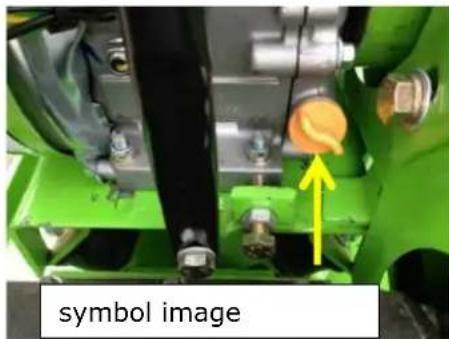
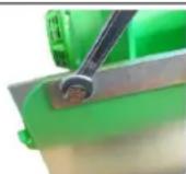
natural_image
Close-up of a green industrial machine component with a yellow arrow pointing to a yellow-orange knob, labeled 'symbol image' below (no other text or symbols)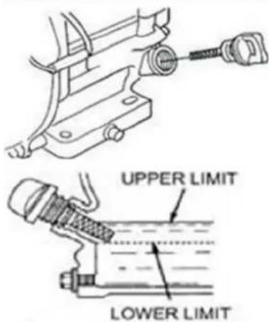
- To check the engine oil level, place the machine on a safe, level surface. Switch off the engine and allow the machine to stand for ten minutes so that the circulating oil can collect in the oil pan.
-
Unscrew the oil dipstick and wipe with a clean, lint-free cloth or a non-fibrous paper towel.
-
Push the dipstick into the opening, but do not screw it in. (Make sure that the dipstick has really been pushed in completely).
-
Pull out the oil dipstick again and read off the oil level. There are two markings for this - see illustration on the left.
-
If the oil level is low, refill the recommended oil up to the upper edge (maximum filling volume: approx. 0.5 litres).
-
Push in the oil dipstick again and tighten.
15.3.2 Checking the fuel tank level
NOT ICE

Observe the safety regulations for fuel control. Filter the fuel during refuelling to prevent foreign particles from entering the combustion chamber. Wipe up leaked fuel.
- Screw on the tank cap (sits on the fuel tank).
- Level check in the form of a visual inspection. If necessary, top up with fuel with the appropriate octane number (RON 95).
- Close the fuel filler cap tightly after refuelling.
16 OPERATION
- Save the working environment before you start compressing.
- Only put the machine into operation after you have read and understood the safety instructions and carried out the necessary measures before initial commissioning.
- The correct moisture content of the soil is very important for correct compaction. Compaction of dry materials is facilitated by moistening the material. Too much moisture, on the other hand, leaves water-filled cavities which weaken the load-bearing capacity of the soil.
- Wetness or excessive irrigation can lead to overloading and engine death.
16.1 Information on Initial Start-up
NOTICE

Note that the machine is delivered without fuel and engine oil. Make sure that this equipment is filled up before the machine is put into operation for the first time. ATTENTION: The machine does not start until the engine oil has been refilled to the upper limit.
16.1.1 Test Run Initial Start-up
- Let the machine run idle for about 3 minutes.
- Pay attention to abnormal noises.
- Pay attention to the exhaust fumes (too black, too white)?
16.1.2 Notes on the first 20 operating hours
In order to optimize the life expectancy of your machine, the following points should be observed:
- Do not operate the engine for the first 20 operating hours @ maximum load (this also applies to used engines after extensive maintenance). This means lower speed and lower maximum working load than during normal operation.
- Change the engine oil after the first 20 hours of operation.
16.2 Operating Instructions
- Never use the recoil-starter while the engine is running. This will damage the engine.
- The pull mechanism for changing the engine speed is limited by an adjusting screw. This is factory set. Never change this setting on your own, you could overload the motor.
- Do not operate the machine on slopes of more than 20^ , as even with an optimum oil level the engine may not be supplied with sufficient lubrication.
- In the direction of the vibratory plate and within a range of one meter around the vibrator, nobody but the operator must stand.
- During the compaction the soil should first be compacted about 10 to 15 cm inside the edge two to three times, then the edge should be compacted.
- When working inside the building, the vibrating plate or eccentric block must not attach the walls.
- If several vibrator plates are used simultaneously on one surface, the parallel distance between the machines should not be less than five metres and the distance between the front and rear machines should not be less than ten metres.
- If the machine is working in an environment e.g. on soft or uneven ground, make sure to reduce the horsepower to the lowest level to prevent the machine from sinking. On slopes (max. 20° allowed!!!), make sure that the machine does not tilt.
• Pay particular attention to the following particularly dangerous areas:
- During tunnel work, good ventilation must be provided to prevent accidents. In addition, the ventilation must be monitored.
16.3 Starting the Machine
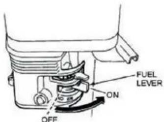 | Turn the fuel valve to the "ON" position. |
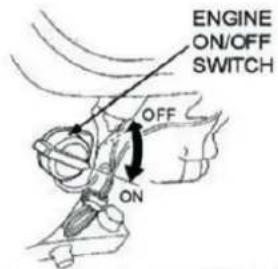 | Set the engine ON/OFF switch (ignition switch) also to the "On" position. |
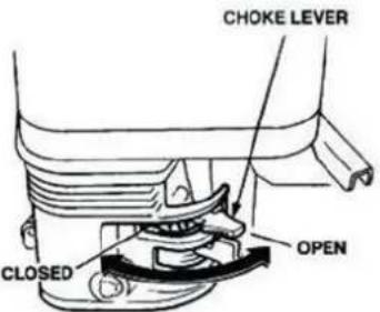 | Note: The closed position of the choke lever enriches the fuel mixture for starting a cold engine. The open position provides the correct fuel mixture for normal operation after starting and for restarting a warm engine.Turn the choke lever to the "Closed" position, only for cold engine. |
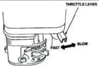 | |
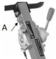
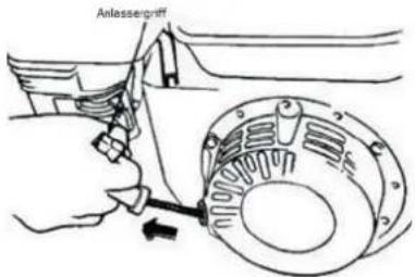 | 4. Set the throttle lever to "half throttle" (= middle position between "fast" and "slow").Note: Do not pull the starter rope through to the end and do not let it rewind after pulling, but only rewind it quickly.Grab the starter handle and pull it out slowly. The resistance becomes strongest at a certain point. This point corresponds to the compression point. Let the rope roll back a little from this point and then pull it out powerfully.Turn the choke lever to "Open when the engine is running.Open throttle (A) further machine start compacting. |
 |
16.4 Stopping the Machine
16.4.1 Emergency Stop
In case of danger and/or in an emergency situation, you can quickly switch off the machine with the speed governor by pushing it completely into the STOP position.
16.4.2 Normal switch-off
- Set the upper throttle lever to "minimum" and let the engine run idle for approx. 3 minutes at low engine speed.
- Then set the engine ON/OFF switch (ignition switch) to the OFF position.
- Close the fuel switch.
- Wait until the engine has cooled down before storing the machine.
16.5 Moving machine forward / backward
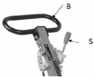
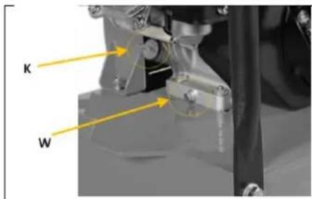
Use the lever (S) to determine the direction of travel. Depending on the position of the lever, the machine moves forwards or backwards.
The machine should be steered at the bracket (B).
Note for reverse driving:
Operate the machine from the side + pay special attention to the working environment (free of obstacles, danger of tripping) to avoid danger of crushing.
17 MAINTENANCE
WARNING

Hot surfaces and rotating machine parts while the engine is running can cause serious injury or even death. Always stop the machine before carrying out any conversion, adjustment, cleaning or maintenance work and secure it against unintentional restarting.
17.1 Maintenance and Servicing PLAN
17.1.1 Table of Measures
| What to do? | Frequency |
| Check fuel level | before each start-up |
| Check engine oil level | before each start-up |
| Control of the operating elements | before each start-up |
| Check for damaged parts | before each start-up |
| Checking for loose or lost screws | before each start-up |
| Change engine oil | first after 20 h, then every 100 h |
| Check V-belt | every 50 h; replacement after 300 h |
| Change exciter oil | every 200 h |
| Air filter cleaning | every 50 h, replacement after 300 h or 1 year |
| Spark plug test | every 100 h; replacement after 300 h or 1 year |
The specified intervals refer to working under "normal" operating conditions. Depending on the load, a change/exchange may also be necessary at an earlier point in time.
17.2 Changing the exciter oil
| NOTICE | ||
| Waste oils are toxic and must not be released into the environment! Contact your local authorities for information on proper disposal. | ||
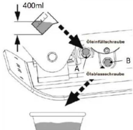 | To drain the exciter oil, remove the drain screw (B) on the exciter. Then tilt the machine. Fix the drain screw (B) again and fill up fresh oil (screw (A)). Recommended oil is ISO VG68 or similar about 400ml is needed for a refill. | |
17.3 Changing the engine oil
| NO TICE | ||
 |  | Waste oils are toxic and must not be released into the environment! Contact your local authorities for information on proper disposal. |
17.4 Cleaning the air filter
A contaminated air filter can contribute to problems starting the machine, loss of performance during operation and shorten engine life.
Zipper Machines does not accept any liability for engine damage caused by failure to clean the air filter regularly.
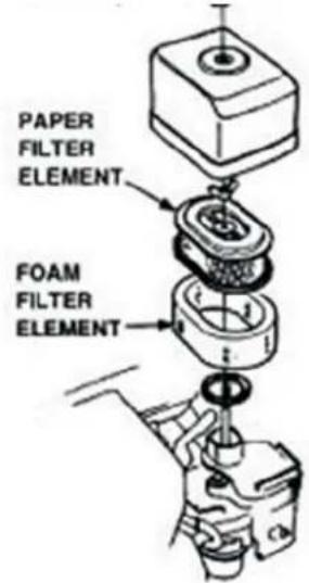
To clean the air filter, first loosen the wing nut on the air filter housing, remove the cover (foam filter element) and remove the air filter cassette (paper filter element). Clean both elements mechanically with a soft brush.
If only the air filter cassette is to be cleaned, blow a dry jet of compressed air from the inside against the filter until all dust has been removed.
An air filter change is necessary when:
- The engine power drops and the fuel consumption increases at the same time.
• the oil consumption increases
• the starting of the engine becomes more difficult
17.5 Checking and replacing V-belt and coupling
WARNING

Warning of danger of detection/trapping in! Never attempt to check the V-belt while the engine is running. Your hands could get caught between the V-belt and the clutch. Serious hand injuries are the result.
NO TICE

If the vibratory power of the machine - regardless of the number of operating hours - suddenly decreases or stops completely during normal operation, first of all check the V-belt and clutch.
Loose or worn V-belts reduce power transmission efficiency, result in poor compaction performance and shorten the service life of the belt itself. Therefore, always check the V-belt tension at the specified intervals.
17.5.1 Checking the V-belt tension
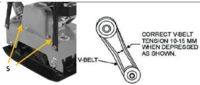
- Loosen V-belt cover screws (S) and remove them.
- Check tension:
V-belt tension is OK if the belt yields approx. 10 to 15 mm under pressure with thumb and index finger (see illustration on the left). If the V-belt is too loose or too tight, adjust the tension! - Remount V-belt cover after having checked/corrected V-belt tension!
17.5.2 Tensioning the V-Belt
The V-belt is tensioned by moving the engine block on the vibratory plate.
- Remove the V-Belt protection cover.
- Loosen the four nuts (M) securing the motor unit to the base plate until the motor can be moved with the eccentric discs (S).
a. Discs (S) in upper position = tighten the belt.
b. Discs (S) in lower position = Loosen the belt.
- Once the belt has the correct tension, retighten the four nuts securing the motor unit to the base plate.
- Finally, retighten the V-belt protection cover.
17.5.3 Changing the V-belt
- Loosen the V-belt.
- Then pull over the V-belt over the pulleys.
- Clean the drive wheels including the V-groove and the inside of the protective cover.
- Install the new V-belt and tension the V-belt again.
- Finally, reattach the V-belt protective cover.
17.5.4 Checking the clutch
Check the clutch at the same time as the V-belt. With the belt removed, visually check the outside for seizure and the "V" groove for wear and damage. Clean the V-groove as required. If the clutch shoe is worn, the power transmission becomes insufficient.
17.6 Cleaning the spark plug
- Pull out the spark plug cap and remove impurities from the outside of the spark plug.
- Unscrew the spark plug using the spark plug wrench.
- Check the ceramic insulation, clean the electrodes (metal tips) and check the distance between the contacts. It should be 0.7 to 0.8 mm.
- Reinstall the cleaned (or replaced) spark plug and replace the spark plug cap.
18 TRANSPORT
WARNING

Never lift or transport the machine with the engine running!
18.1 Transport over shorter distances
For transport over short distances, use the hand holder and the mounted transport wheels.
18.2 Lifting and transporting with separate devices
NO TICE

There are two persons required to lift and park the machine on another transporting devices. - one person to operate the hoist and one person to keep the machine in balance.
- When transporting over long distances, fold the handle forward as far as possible.
- Ensure that the lifting equipment, incl. accessories, is suitable for loads greater than 130 kg.
- Before lifting, check the weld on the lifting ring and the fixing of the lifting frame.
- First lift the machine only a few centimetres to check the load capacity.
- Then lift the machine as gently as possible into the desired position.
- Secure the load properly for transport.
19 STORAGE
If the machine is not used for a longer period of time (>30 days):
- Empty the oil tanks or fuel tank.
- Remove the spark plug and pour a few drops of engine oil into the cylinder. Using a rope starter, turn the engine a few times so that the oil is well distributed inside the cylinder. Clean the spark plug and replace it.
- Cover the cooled machine and store it out of the reach of children and unauthorised persons in a well-ventilated, dry and frost-free environment.
20 RECYCLING

Do not dispose of your machine in residual waste. Contact your local authorities for information on available disposal options. If you buy a new vibratory plate or equivalent from your dealer, he is obliged in certain countries to dispose of your old machine properly.
21 TROUBLESHOOTING
WARNING

Hot surfaces and rotating machine parts while the engine is running can cause serious injury or even death. Always stop the machine before carrying out troubleshooting work and secure it against unintentional restarting.
| Fault | Possible cause / remedy |
| Motor does not start | Check ON/OFF switch and make sure it is positioned to "ON".Check fuel supply.Check engine oil level (a sensor prevents starting if oil level is too low).Make sure that the spark plug ignition cable is connected.Check spark plugCheck carburettor and air filter and make sure they are clean. |
| Motor stops | Check fuel supply.Check that the fuel tap is open.Check oil levels.Check the condition of the air filter. |
| Engine does not deliver enough power: | Check fuel supply.Check that the fuel tap is open.Check the condition of the air filter.Check throttle position |
| Insufficient vibration | Check whether the V-belt slips or is lost.Check throttle position |
| Machine does not move freely | Check the underside of the disc for buildup. |
22 ERSATZTEILE / SPARE PARTS
(EN) With ZIPPER spare parts you use spare parts that are ideally matched to each other. The fitting accuracy of the parts shortens their installation time and increases the service life of the machine.
NO TE
The installation of parts other than original spare parts leads to the loss of the guarantee! Therefore, when replacing components/parts, only use original spare parts!
When ordering spare parts, please use the service form at the end of this manual. Always state machine type, spare part number and designation. In order to avoid misunderstandings, we recommend enclosing a copy of the spare part drawing with the spare part order, on which the required spare parts are clearly marked.
You will find the ordering address under customer service addresses in the foreword to this documentation.
| PART NO. | DESCRIPTION | QTY | PART NO. | DESCRIPTION | QTY |
| 01 | Hexagonal bolt M8*30 | 1 | Vibrator control switch | 1 | |
| 02 | Spring washer ¢8 | 1 | Vibrator control cable | 1 | |
| 03 | Washer ¢8 | 1 | 21 | nut M16 | 2 |
| 04 | Clutch assembly | 1 | 22 | washer ¢16 | 2 |
| 05 | V-belt | 1 | 23 | base plate | 1 |
| 06 | Engine | 1 | 24 | Vibrator assembly | 1 |
| 07 | Nut M10 | 4 | 25 | Hexagonal bolt M12*55 | 4 |
| 08 | Spring washer ¢10 | 4 | 26 | washer ¢10 | 4 |
| 09 | Washer ¢10 | 4 | 27 | upper plate | 1 |
| 10 | Protective frame | 1 | 28 | Belt cover(upper) | 1 |
| 11 | Throttle lever Assy | 1 | 29 | washer ¢8 | 2 |
| Throttle lever | 1 | 30 | spring washer ¢8 | 2 | |
| Throttle cable | 1 | 31 | Socket head bolt M8*16 | 2 | |
| 12 | Grip | 1 | 32 | Fixed rubber collar | 1 |
| 13 | Handle | 1 | 33 | Shock absorber for base plate | 4 |
| 14 | Shock absorber for handle | 2 | 34 | washer ¢12 | 4 |
| 15 | Hexagonal bolt M8*30 | 4 | 35 | Nut M12 | 4 |
| 16 | platter plate | 2 | 36 | Extension plate (Optional ) | 2 |
| 17 | lining tube | 2 | 37 | washer ¢16 | 6 |
| 18 | washer ¢12 | 2 | 38 | spring washer ¢16 | 6 |
| 19 | Hexagonal bolt M12*55 | 2 | 39 | Hexagonal bolt M16*45 | 6 |
| 20 | Vibrator control Assembly | 1 | 40 | locknut for handle | 1 |
| PART NO. | DESCRIPTION | PART NO. | DESCRIPTION | ||
| 24-52 | Belt cover (below) | 1 | 24-85 | Cover, cylinder | 1 |
| 24-53 | flat screw M8*20 | 1 | 24-86 | spring washer 6 | 3 |
| 24-54 | Spring washer 8 | 1 | 24-87 | Socket head bolt M6*20 | 3 |
| 24-55 | dished washer 8 | 1 | 24-88 | Socket head bolt M8 | 1 |
| 24-56 | Driven pulley wheel for belt | 1 | 24-89 | Knock pin | 4 |
| 24-57 | Bearing cover for pulley | 1 | 24-90 | Position rod | 2 |
| 24-58 | paper cushion | 2 | 24-91 | Groove | 1 |
| 24-59 | Oil seal 28*50*10 | 1 | 24-92 | Washer 5*32*2.5 | 1 |
| 24-60 | case of vibrator | 1 | 24-93 | Spring Washer 5 | 4 |
| 24-61 | bearing cover | 1 | 24-94 | Socket head boltM5*16 | 1 |
| 24-62 | paper cushion | 1 | 24-95 | Rotator | 1 |
| 24-63 | Bearing NJ206 | 1 | 24-96 | Oil seal 20*30*6 | 1 |
| 24-64 | clamp spring 42 | 1 | 24-97 | O-ring | 1 |
| 24-65 | Socket head bolt M8*20 | 3 | 24-98 | clamp spring | 1 |
| 24-66 | Spring washer 8 | 1 | 24-99 | Oil drain screw M14*1.5 | 1 |
| 24-67 | Bearing cover / shut-off | 1 | 24-100 | Copper washer | 1 |
| 24-68 | Socket head bolt M10*65 | 1 | 24-101 | paper cushion, cylinder | 1 |
| 24-69 | nut M10 | 2 | 24-102 | Bearing | 2 |
| 24-70 | spring | 1 | 24-103 | clmap spring 40 | 2 |
| 24-71 | Stopper | 1 | 24-104 | Bolt, dial plate M8*30 | 4 |
| 24-72 | Thread pin M20 | 1 | 24-105 | lock-nut M8 | 4 |
| 24-73 | Eccentric rotator, drive | 1 | 24-106 | Screw | 4 |
| 24-74 | flat key 8*20 | 1 | 24-107 | washer | 4 |
| 24-75 | Main shaft | 1 | 24-108 | Socket screw M8*20 | 1 |
| 24-76 | flat key 12*50 | 1 | 24-109 | Hex bolt M10*25 | 12 |
| 24-77 | flat key 12*20 | 1 | 24-110 | Spring washer 10 | 2 |
| 24-78 | Driven gear | 1 | 24-111 | Vibrating case | 1 |
| 24-79 | Eccentric rotator, driven | 1 | 24-112 | Bearing 16008 | 2 |
| 24-80 | Ecc.rotary shaft, driven | 1 | 24-113 | Lever | 1 |
| 24-81 | Dial plate(R/L) | 1 | 24-114 | Holder | 1 |
| 24-82 | Gear, driven | 1 | 24-115 | Socket head bolt M10*25 | 2 |
| 24-83 | Cylinder | 1 | 24-116 | washer 10 | 2 |
| 24-84 | paper cushion | 1 |
ÄHRLEISTUNG (DE)
1.) Gewährleistung:
Company ZIPPER Maschinen GmbH grants for mechanical and electrical components a warranty period of 2 years for amateur use; and warranty period of 1 year for professional use, starting with the purchase of the final consumer. In case of defects during this period, which are not excluded by paragraph 3, ZIPPER will repair or replace the machine at its own discretion.
2.) Report:
In order to check the legitimacy of warranty claims, the final consumer must contact his dealer. The dealer has to report in written form the occurred defect to ZIPPER. If the warranty claim is legitimate, ZIPPER will pick up the defective machine from the dealer. Returned shippings by dealers which have not been coordinated with ZIPPER, will not be accepted and refused.
3.) Regulations:
a) Warranty claims will only be accepted, when a copy of the original invoice or cash voucher from the trading partner of ZIPPER is enclosed to the machine. The warranty claim expires if the accessories belonging to the machine are missing.
b) The warranty does not include free checking, maintenance, inspection or service works on the machine. Defects due to incorrect usage of the final consumer or his dealer will not be accepted as warranty claims either. Some examples: usage of wrong fuel, frost damages in water tanks, leaving fuel in the tank during the winter, etc.
c) Defects on wear parts are excluded, e.g. carbon brushes, collection bags, knives, cylinders, cutting blades, clutches, sealings, wheels, saw blades, splitting crosses, riving knives, riving knife extensions, hydraulic oils, oil/air/fuel filters, chains, spark plugs, sliding blocks, etc.
d) Also excluded are damages on the machine caused by incorrect or inappropriate usage, if it was used for a purpose which the machine is not supposed to, ignoring the user manual, force majeure, repairs or technical manipulations by not authorized workshops or by the customer himself, usage of non-original ZIPPER spare parts or accessories.
e) After inspection by our qualified personnel, resulted costs (like freight charges) and expenses for not legitimated warranty claims will be charged to the final customer or dealer.
f) In case of defective machines outside the warranty period, we will only repair after advance payment or dealer's invoice according to the cost estimate (incl. freight costs) of ZIPPER.
g) Warranty claims can only be granted for customers of an authorized ZIPPER dealer who directly purchased the machine from ZIPPER. These claims are not transferable in case of multiple sales of the machine.
4.) Claims for compensation and other liabilities:
The liability of company ZIPPER is limited to the value of goods in all cases. Claims for compensation because of poor performance, lacks, damages or loss of earnings due to defects during the warranty period will not be accepted. ZIPPER insists on its right to subsequent improvement of the machine.
Please describe amongst others in the problem: What has cause the problem/defect, what was the last activity before you noticed the problem/defect? For electrical problems: Have you had checked you electric supply and the machine already by a certified electrician?
3. Bitte beachten
/ Additional information
INCOMPLETELY FILLED SERVICE FORMS CANNOT BE PROCESSED! FOR GUARANTEE CLAIMS PLEASE ADD A COPY OF YOUR ORIGINAL SALES/ DELIVERY RECEIPT OTHERWISE IT CANNOT BE ACCEPTED. FOR SPARE PART ORDERS PLEASE ADD TO THIS SERVICE FORM A COPY OF THE RESPECTIVE EXPLODED DRAWING WITH THE REQUIRED SPARE PARTS BEING MARKED CLEARLY AND UNMISTAKABLE. THIS HELPS US TO IDENTIFY THE REQUIRED SPARE PARTS FASTLY AND ACCEL- LERATES THE HANDLING OF YOUR INQUIRY.