AVIC-800DVD - GPS Navigation System PIONEER - Free user manual and instructions
Find the device manual for free AVIC-800DVD PIONEER in PDF.
| Product Type | GPS navigation system with DVD player |
| Brand | PIONEER |
| Model | AVIC-800DVD |
| Power Supply | 12 V DC, negative ground |
| Main Functions | GPS navigation, DVD playback, voice guidance, voice control |
| Safety | Do not use while driving; installation and maintenance by qualified personnel recommended |
| Installation Type | Front or rear DIN mount |
| GPS Antenna | Magnetic antenna, indoor or outdoor installation |
| Microphone | Microphone for voice control, installation on sun visor or steering column |
| Remote Control | Control remote with CR2032 lithium battery |
| Screen Connectivity | 26-pin or 20-pin cable for external screen (e.g., AVH-P7500DVD) |
| Wiring Inputs/Outputs | Speed signal (pink), reverse light (violet/white), parking brake (light green), illumination (orange/white), audio mute (yellow/black) |
| Included Accessories | GPS antenna, remote with battery, microphone, cables, brackets, metal plate, wire ties, waterproof cushion |
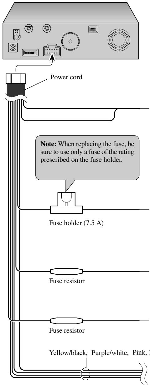
| Maintenance | Clean with a dry cloth; replace fuse with one of same amperage (7.5 A) |
| Repairability | Entrust maintenance to qualified Pioneer personnel; do not attempt repairs yourself |
Frequently Asked Questions - AVIC-800DVD PIONEER
User questions about AVIC-800DVD PIONEER
0 question about this device. Answer the ones you know or ask your own.
Ask a new question about this device
Download the instructions for your GPS Navigation System in PDF format for free! Find your manual AVIC-800DVD - PIONEER and take your electronic device back in hand. On this page are published all the documents necessary for the use of your device. AVIC-800DVD by PIONEER.
USER MANUAL AVIC-800DVD PIONEER
This product conforms to new cord colours.
ABOUT YOUR NEW DVD NAVIGATION UNIT AND THIS MANUAL
- The Pioneer DVD Navigation Unit is intended solely as an aid to you in the operation of your vehicle. It is not a substitute for your attentiveness, judgement and care while driving.
- Do not use your navigation system to route you to emergency services such as hospitals or police stations. Not all emergency service facilities are contained in the map data.
- Do not operate the DVD Navigation Unit if doing so will divert your attention from the safe operation of your vehicle. Always observe safe driving rules and follow all existing traffic regulations.
- This manual explains how to install this DVD Navigation Unit in your vehicle. Operation of this DVD Navigation Unit is explained in the separate “Operation Manual” or “Hardware Manual” that also came with this unit.
IMPORTANT SAFEGUARDS .... 3
PLEASE READ ALL OF THESE
INSTRUCTIONS REGARDING
YOUR DVD NAVIGATION
UNIT AND RETAIN THEM
FOR FUTURE REFERENCE .... 3
Connecting the System 4
CAUTION 4
● Before installing the unit
● To prevent damage
- Parts supplied
Connecting the system 7
- Connecting to the display with 26-pin input
(AVH-P7500DVD, AVH-P6500DVD, etc.)
- Connecting to the display with 20-pin input
Connecting the power cord (1) 9
Connecting the power cord (2) 11
Installation 12
CAUTION 12
To guard against electromagnetic interference ....13
Before installing and fixing 13
Before using the adhesive tape 13
Installing the main unit 14
- Installation notes
- Parts supplied
- CAUTION
- If you install with the left and right sides of the DVD Navigation Unit parallel to your vehicle's forward / backward direction
DIN Front/Rear-mount 17
DIN Front-mount 17
● Installation with the rubber bush
- Removing the Unit
DIN Rear-mount 18
● Installation using the screw holes on the side of the unit
Installing the GPS aerial 19
- CAUTION
- Installation notes
- Parts supplied
- When installing the aerial inside the vehicle (on the dashboard or rear shelf)
- When installing the aerial outside the vehicle (on the body)
Installing the steering remote control 22
- Parts supplied
- Loading the battery
● Remote control handling notes
- Installing the holders and the steering remote control
Installing the microphone 25
- Installation notes
- Parts supplied
- When installing the microphone on the sun visor
- When installing the microphone on the steering column
- CAUTION
After installing the unit 28
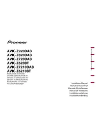
PLEASE READ ALL OF THESE INSTRUCTIONS REGARDING YOUR DVD NAVIGATION UNIT AND RETAIN THEM FOR FUTURE REFERENCE
- Read this manual fully and carefully before installing your DVD Navigation Unit.
- Keep this manual handy for future reference.
- Pay close attention to all warnings in this manual and follow the instructions carefully.
- This unit is intended solely as an aid to you in the operation of your vehicle. It is not a substitute for your attentiveness, judgement and care while driving. Do not operate your DVD Navigation Unit if doing so will divert your attention from the safe operation of your vehicle. Always observe safe driving rules and follow all existing traffic regulations.
- This DVD Navigation Unit may in certain circumstances display erroneous information regarding the position of your vehicle, the distance of objects shown on the screen, and compass directions. In addition, the system has certain limitations, including the inability to identify one-way streets, temporary traffic restrictions and potentially unsafe driving areas. Please exercise your own judgement in light of actual driving conditions.
- As with any accessory in your vehicle's interior, the DVD Navigation Unit should not divert your attention from the safe operation of your vehicle. If you experience difficulty in operating the system or reading the display, please make adjustments while safely parked.
- Do not attempt to install or service your DVD Navigation Unit by yourself. Installation or servicing of the DVD Navigation Unit by persons without training and experience in electronic equipment and automotive accessories may be dangerous and could expose you to the risk of electric shock or other hazards.
- Please remember to wear your seat belt at all times while operating your vehicle. If you are ever in an accident, your injuries can be considerably more severe if your seat belt is not properly fastened.

CAUTION
- Pioneer does not recommend that you install or service your DVD navigation unit yourself. Installing or servicing of the product may expose you to risk of electric shock or other hazards. Refer all installation and servicing of your navigation unit to authorised Pioneer service personnel.
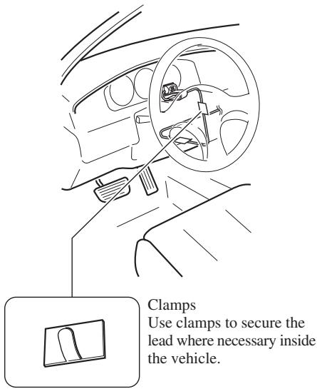
- Secure all wiring with cable clamps or electrical tape. Do not allow any bare wiring to remain exposed.
- Do not drill a hole into the engine compartment to connect the yellow lead of the unit to the vehicle battery. Engine vibration may eventually cause the insulation to fail at the point where the wire passes from the passenger compartment into the engine compartment. Take extra care in securing the wire at this point.
- It is extremely dangerous to allow the GPS aerial cable or microphone cable to become wound around the steering column or gearstick. Be sure to install the unit in such a way that it will not obstruct driving.
- Make sure that wires will not interfere with moving parts of the vehicle, such as the gearstick, handbrake or seat sliding mechanism.
- Do not route wires where they will be exposed to high temperatures. If the insulation heats up, wires may become damaged, resulting in a short circuit or malfunction.
- Do not cut the GPS aerial cable to shorten it or use an extension to make it longer. Altering the aerial cable could result in a short circuit or malfunction.
- Do not shorten any leads. If you do, the protection circuit may fail to work properly.
- Never feed power to other electronic products by cutting the insulation of the power supply lead of the DVD navigation unit and tapping into the lead. The current capacity of the lead will be exceeded, causing overheating.
Before installing the unit
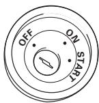
- This unit is for vehicles with a 12-volt battery and negative grounding. Before installing it in a recreational vehicle, lorry, or bus, check the battery voltage.
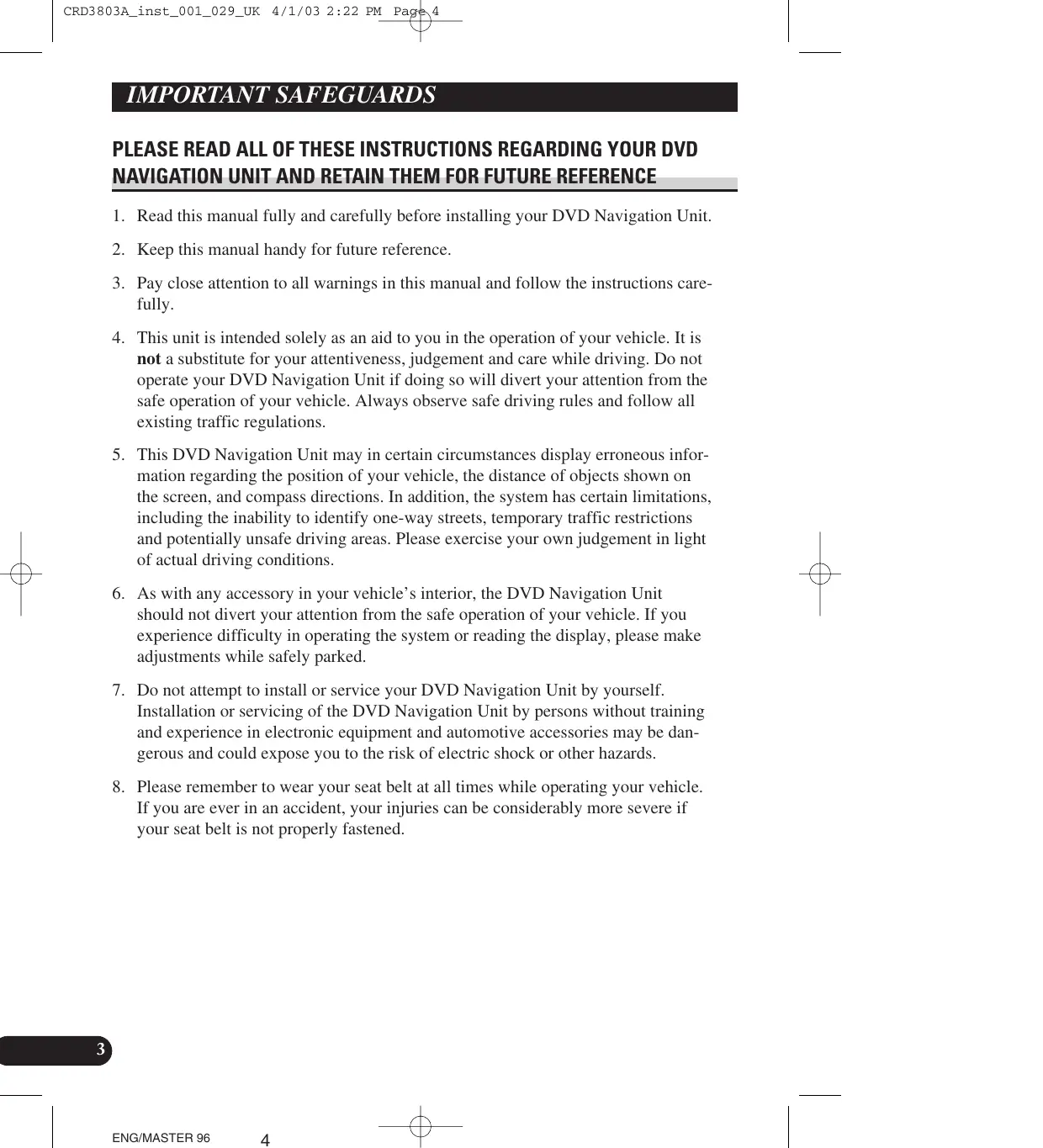
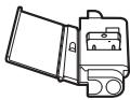
- To avoid shorts in the electrical system, be sure to disconnect the (-) battery cable before beginning installation.
natural_image
Illustration of a hand holding a battery with a switch and power plug (no text or symbols)To prevent damage
- When disconnecting a connector, pull the connector itself. Do not pull the lead, as you may pull it out of the connector.
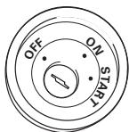
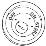
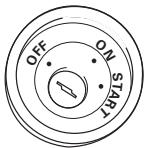
- If this unit is installed in a vehicle that does not have an ACC (accessory) position on the ignition switch, the red lead of the unit should be connected to a terminal coupled with ignition switch ON/OFF operations. If this is not done, the vehicle battery may be drained when you are away from the vehicle for several hours.
- To avoid short-circuiting, cover the disconnected lead with insulating tape.
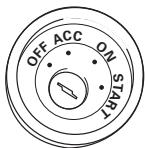
ACC position
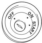
No ACC position
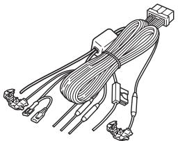
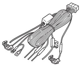
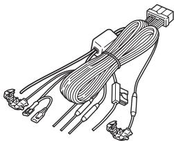
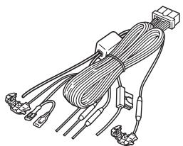
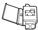
Parts supplied
natural_image
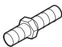
Line drawing of a multi-wire electrical connector with terminal connectors and wires (no text or symbols)Power cord
Connector
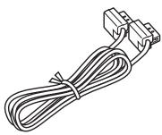
natural_image
Line drawing of a cable with two connectors (no text or symbols)26-pin cable
Connecting the system
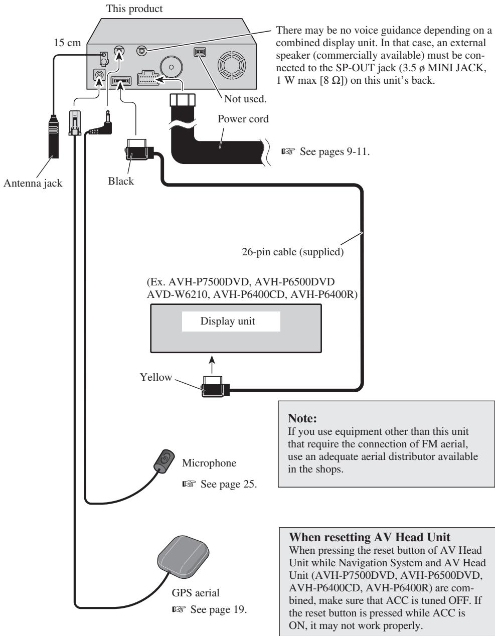
Connecting to the display with 26-pin input (AVH-P7500DVD, AVH-P6500DVD, etc.)
flowchart
graph TD
    A["Antenna jack"] --> B["15 cm"]
    B --> C["This product"]
    C --> D["Not used."]
    C --> E["Power cord"]
    C --> F["See pages 9-11."]
    C --> G["Black"]
    G --> H["26-pin cable (supplied)"]
    H --> I["(Ex. AVH-P7500DVD, AVH-P6500DVD AVD-W6210, AVH-P6400CD, AVH-P6400R)"]
    I --> J["Display unit"]
    J --> K["Yellow"]
    K --> L["Microphone"]
    L --> M["See page 25."]
    M --> N["GPS aerial"]
    N --> O["See page 19."]
    style A fill:#f9f,stroke:#333
    style B fill:#ccf,stroke:#333
    style C fill:#cfc,stroke:#333
    style D fill:#fcc,stroke:#333
    style E fill:#cff,stroke:#333
    style F fill:#ffc,stroke:#333
    style G fill:#cfc,stroke:#333
    style H fill:#fcc,stroke:#333
    style I fill:#ffc,stroke:#333
    style J fill:#cfc,stroke:#333
    style K fill:#fcc,stroke:#333
    style L fill:#ffc,stroke:#333
    style M fill:#cfc,stroke:#333
    style N fill:#fcc,stroke:#333
    style O fill:#ffc,stroke:#333
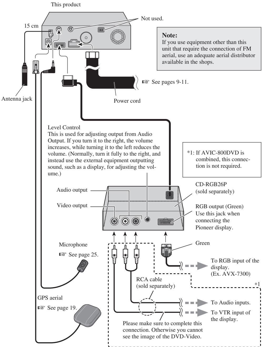
Connecting to the display with 20-pin input
flowchart
graph TD
    A["This product"] -->|Not used.| B["Antenna jack"]
    B --> C["Level Control"]
    C --> D["Audio output"]
    C --> E["Video output"]
    D --> F["CD-RGB26P (sold separately)"]
    E --> G["RGB output (Green) Use this jack when connecting the Pioneer display."]
    F --> H["To RGB input of the display. (Ex. AVX-7300)"]
    G --> I["To Audio inputs."]
    G --> J["To VTR input of the display."]
    K["GPS aerial"] --> L["See page 19."]
    L --> M["Microphone See page 25."]
    M --> N["RCA cable (sold separately)"]
    N --> O["Please make sure to complete this connection. Otherwise you cannot see the image of the DVD-Video."]
    style A fill:#f9f,stroke:#333
    style B fill:#ccf,stroke:#333
    style C fill:#cfc,stroke:#333
    style D fill:#fcc,stroke:#333
    style E fill:#cff,stroke:#333
    style F fill:#ffc,stroke:#333
    style G fill:#fcc,stroke:#333
    style H fill:#cfc,stroke:#333
    style I fill:#cfc,stroke:#333
    style J fill:#cfc,stroke:#333
    style K fill:#fcc,stroke:#333
    style L fill:#cfc,stroke:#333
    style M fill:#cfc,stroke:#333
    style N fill:#fcc,stroke:#333
    style O fill:#cfc,stroke:#333
Connecting the power cord (1)
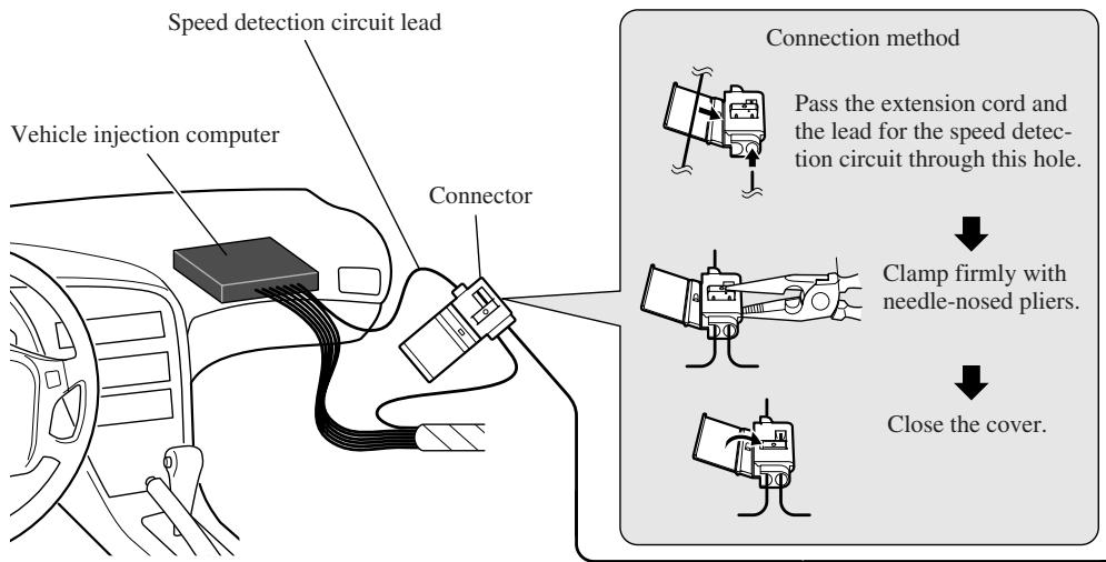
Note: The position of the speed detection circuit depends on the vehicle model. For details, consult the relevant documents from Pioneer. When making connections for a model not listed in those documents or for which connection to the speed detection circuit is too difficult, connect the separately sold ND-PG1 speed pulse generator to the pink lead.
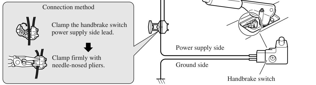
Note: The position of the hand-brake switch depends on the vehicle model. For details, consult the vehicle owner's manual or dealer.
Pink (CAR SPEED SIGNAL INPUT)
The mobile navigation system is connected here to detect the distance the vehicle travels. Always connect the vehicle's speed detection circuit or the ND-PG1 speed pulse generator, sold separately. Failure to make this connection will increase errors in the location display.
WARNING: IMPROPER CONNECTION MAY RESULT IN SERIOUS DAMAGE OR INJURY INCLUDING ELECRICAL SHOCK, AND INTERFERENCE WITH THE OPERATION OF THE VEHICLE'S ANTILOCK BRAKING SYSTEM, AUTOMATIC TRANSMISSION AND SPEEDMETER INDICATION.
Lightgreen
Used to detect the ON/OFF status of the handbrake. This lead must be connected to the power supply side of the handbrake switch. If this connection is made incorrectly or omitted, certain functions of your navigation system will be unusable.
![This product Power cord Black, Orange/white, Red, Yellow See Page 11. Yellow/black When combining this navigation unit with a Pioneer car stereo, if the car stereo has yellow/black leads, connect them to those leads. In this way, when the guidance audio is output and when you operate the system by voice, the vehicle stereo is automatically muted to reduce the vehicle stereo volume. Purple/white (REVERSEGEAR SIGNAL INPUT) This is connected so that the navigation system can detect whether the vehicle is moving forwards or backwards. Connect the purple/white lead to the lead whose voltage changes when the reverse gear is engaged. Unless connected, the sensor may not detect your vehicle travelling forward/backward properly, and thus the position of your vehicle detected by the sensor may be misaligned from the actual position. Note: When you use the ND-PG1 speed pulse generator (sold separately), please make sure to connect it. Fuse resistor Connection method Clamp the reversing lamp lead. Clamp firmly with needle-nosed pliers. Reversing lamp lead. Check the position of your vehicle's reversing lamp (the one that lights up when the gearstick is in reverse [R]) and find the reversing lamp lead in the boot.](/content/2020/05/76388/images/5fa4547a2b8c058dd5aadf66881e2d37dcaf89ff5fb7e7682caf37029e825d6f.jpg)
Connecting the power cord (2)
This product
Note:
Cords for this product and those for other products may be different colours even if they have the same function. When connecting this product to another product, refer to the supplied Installation manuals of both products and connect cords that have the same function.
Black
To vehicle (metal) body. To keep electromagnetic noise from the vehicle body out of the mobile navigation system, attach this lead near the main unit.
Note: The yellow, red, and orange/white leads should be connected to the opposite side of the fusebox terminals from the battery.
Yellow
To the terminal always supplied with power regardless of ignition switch position.
Red
To the electric terminal controlled by the ignition switch (12 V DC) ON/OFF.
Do not connect this lead to power source terminals to which power is continuously supplied. If the lead is connected to such terminals, the battery may be drained.
Orange/white
To lighting switch terminal.
See pages 9-11.

CAUTION
- Pioneer does not recommend that you install or service your DVD navigation unit yourself. Installing or servicing the product may expose you to risk of electric shock or other hazards. Refer all installation and servicing of your navigation unit to authorised Pioneer service personnel.
- Never install the unit in places where:
* It could injure the driver or passengers if the vehicle stops suddenly.
* It may interfere with the driver's operation of the vehicle, such as on the floor in front of the driver's seat. - Make sure there is nothing behind the dashboard or panelling when drilling holes in them. Be careful not to damage fuel lines, brake lines or power cables.
- When using screws, do not allow them to come into contact with any electrical lead. Vibration may damage wires, leading to a short circuit or other damage to the vehicle.
- To ensure proper installation, use the supplied parts in the manner specified. If any parts other than the supplied ones are used, they may damage internal parts of the unit or they may work loose and the unit may become detached.
- It is extremely dangerous to allow the GPS aerial lead or microphone lead to become wound around the steering column or gearstick. Be sure to install the unit in such a way that it will not obstruct driving.
- Make sure that leads cannot get caught in a door or the sliding mechanism of a seat, resulting in a short circuit.
- Please confirm the proper function of your vehicle's other equipment following installation of the DVD navigation unit.
To guard against electromagnetic interference
- In order to prevent interference, set the following items as far as possible from the main unit of this Navigation System, other cables or leads:
- TV aerial and aerial lead
- FM, MW/LW aerial and its lead
- GPS aerial and its lead
In addition you should lay each aerial lead as far as possible from other aerial leads.
Do not bind them together, lay them together, or cross them.
Such electromagnetic noise would increase the error for the location display.
Before installing and fixing
- Consult with your nearest dealer if installation requires the drilling of holes or other modifications of the vehicle.
- Before finally installing the unit, connect the wiring temporarily, making sure it is all connected up properly, and the unit and the system work properly.
Before using the adhesive tape
- Make sure the surface is free of moisture, dust, grime, oil, etc. before affixing the tape.
Installation notes
- Do not install the main unit in places where it may become subject to high temperatures or humidity, such as:
* Places close to a heater outlet.
* Places exposed to direct sunlight, such as on top of the dashboard or the rear shelf.
* Places that may be splashed by rain, for example close to the door.
- The installation strength will depend on the vehicle model and the installation position. Choose a position where the main unit can be firmly installed, and install it securely. If the main unit is not securely fastened, the errors in location display will be greater.
- Do not install the main unit on the board covering the spare tyre or other places which are subject to vibration.
- When the main unit is installed under a front seat, ensure that it does not obstruct the sliding action of the seat.
- Do not install the main unit where it will be under luggage. Strong mechanical shock to the main unit would increase the errors in location display.
- Avoid installing the main unit in places where it will interfere with loading and unloading of the spare tyre, jack, tools, etc.
- Check that a disc or a PC card can be ejected with the main unit installed.
- Install the main unit on a surface within +30 degrees to -15 degrees tolerance (within five degrees to the left or right of your vehicle's direction of travel). A surface tilted more than this would increase the errors in location display.
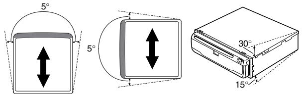
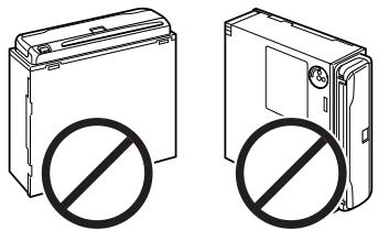
- Do not install the main unit vertically. Installing it this way can cause it to function improperly.
natural_image
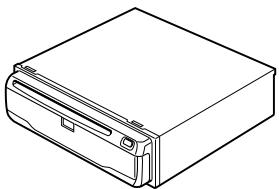
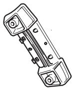
Two identical electronic devices with no visible text or symbols, each marked with a prohibition symbol (no text or labels present)Parts supplied
natural_image
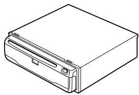
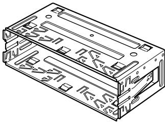
Line drawing of a rectangular electronic device with a side panel and mounting bracket (no text or symbols)Main unit
Screw
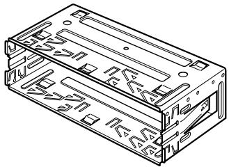
natural_image
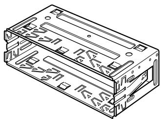
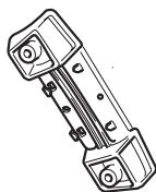
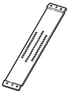
Technical line drawing of a rectangular electronic component with internal structure (no text or symbols)Holder
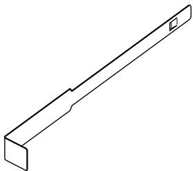
natural_image
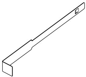
Isometric line drawing of a mechanical bracket or support structure (no text or symbols)Extraction Key (2 pcs.)

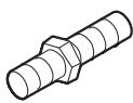
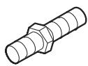
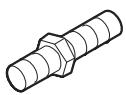
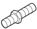
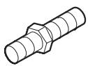
Rubber bush

Binding screw
(5 × 6 mm)
(4 pcs.)

Flush surface screw (5 × 6 mm) (4 pcs.)
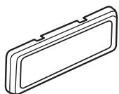
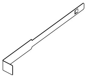
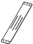
natural_image
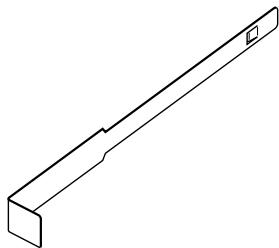
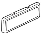
Simple line drawing of a rectangular object with a recessed top and side gap (no text or symbols)Frame

CAUTION
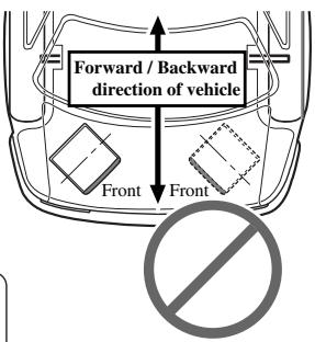
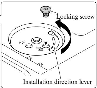
- Install with the left and right sides of the DVD Navigation Unit perpendicular or parallel to your vehicle's direction of travel. Do not install diagonally to your vehicle's direction of travel or the current location will be displayed incorrectly.
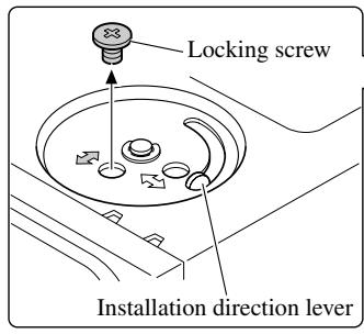
- If you install the left and right sides of the DVD Navigation Unit parallel to your vehicle's direction of travel, switch the installation direction lever, and attach the locking screw to the “ ” side, or else the G sensor mounted in the DVD Navigation Unit will not operate correctly.
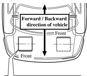
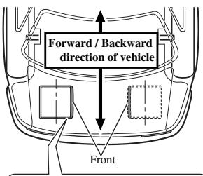
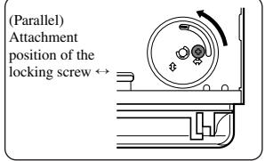
If you install with the left and right sides of the DVD Navigation Unit parallel to your vehicle's forward / backward direction
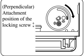
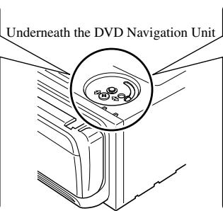
If you install with the left and right sides of the DVD Navigation Unit parallel to your vehicle's forward / backward direction, remove the mounting screw underneath the DVD Navigation Unit, and switch the installation direction lever. Then change the screw mounting position from “↔” side to “↓” side. If the screw is attached to the “↔” side, the G sensor mounted in the DVD Navigation Unit will not operate correctly.
- Remove the locking screw attached to the installation direction lever.
- Switch the lever, and attach the mounting screw to the “↔” side.
DIN Front/Rear-mount
This unit can be properly installed either from “Front” (conventional DIN Front-mount) or “Rear” (DIN Rear-mount installation, utilising threaded screw holes at the sides of unit chassis). For details, refer to the following illustrated installation methods.
DIN Front-mount
Installation with the rubber bush
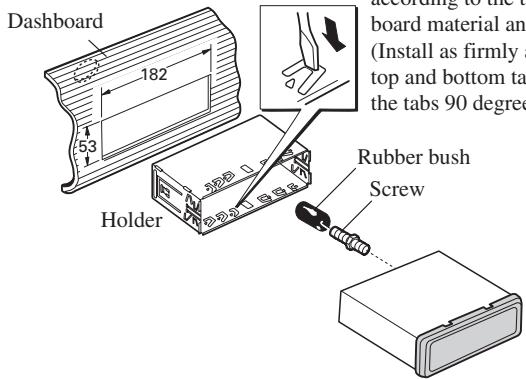
After inserting the holder into the dashboard, then select the appropriate tabs according to the thickness of the dashboard material and bend them. (Install as firmly as possible using the top and bottom tabs. To secure, bend the tabs 90 degrees.)
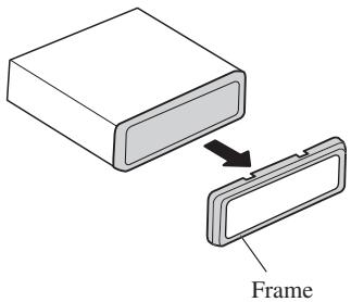
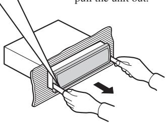
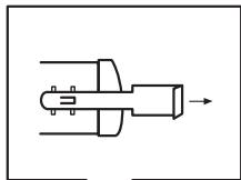
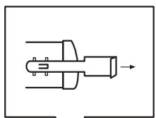
Removing the Unit
Pull out to remove the frame.
(When reattaching the frame, point the side with a groove downwards and attach it.)
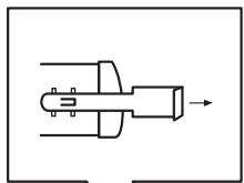
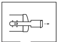
natural_image
Pure mechanical component diagram without any text, numbers, or symbolsInsert the supplied extraction keys into the unit, as shown in the figure, until they click into place. Keeping the keys pressed against the sides of the unit, pull the unit out.
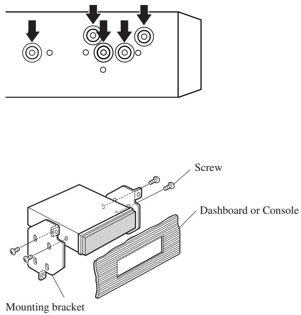
Installation using the screw holes on the side of the unit
- Fastening the unit to the factory radio mounting bracket.
Select a position where the screw holes of the bracket and the screw holes of the head unit become aligned (are fitted), and tighten the screws at 2 places on each side. Use either binding screws (5 × 6 mm) or flush surface screws (5 × 6 mm), depending on the shape of the screw holes in the bracket.

CAUTION
- Do not cut the GPS aerial lead to shorten it or use an extension to make it longer. Altering the aerial cable could result in a short circuit.
Installation notes
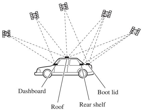
- The aerial should be installed on a level surface where radio waves will be blocked as little as possible. Radio waves cannot be received by the aerial if reception from the satellite is blocked. Installation on the vehicle roof or boot lid is recommended to enable best reception.
- When installing the GPS aerial inside the vehicle, be sure to use the metal sheet provided with your system. If this is not used, the reception sensitivity will be poor.
- Do not cut the accessory metal sheet. This would reduce the sensitivity of the GPS aerial.
- Take care not to pull the aerial lead when removing the GPS aerial. The magnet attached to the aerial is very powerful, and the lead may become detached.
- The GPS aerial is installed with a magnet. When installing the GPS aerial, be careful not to scratch the vehicle body.
- When installing the GPS aerial on the outside of the vehicle, always put it in the vehicle when going through an automatic vehicle wash. If it is left on the outside it may be knocked off and scratch the vehicle body.
- Do not paint the GPS aerial, as this may affect its performance.
Parts supplied
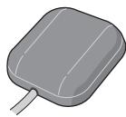
GPS aerial

Metal sheet

Clamp (5 pcs.)

Waterproof pad
When installing the aerial inside the vehicle (on the dashboard or rear shelf)
Affix the metal sheet on as level a surface as possible where the GPS aerial faces outside the window. Place the GPS aerial on the metal sheet. (The GPS aerial is fastened with its magnet.)
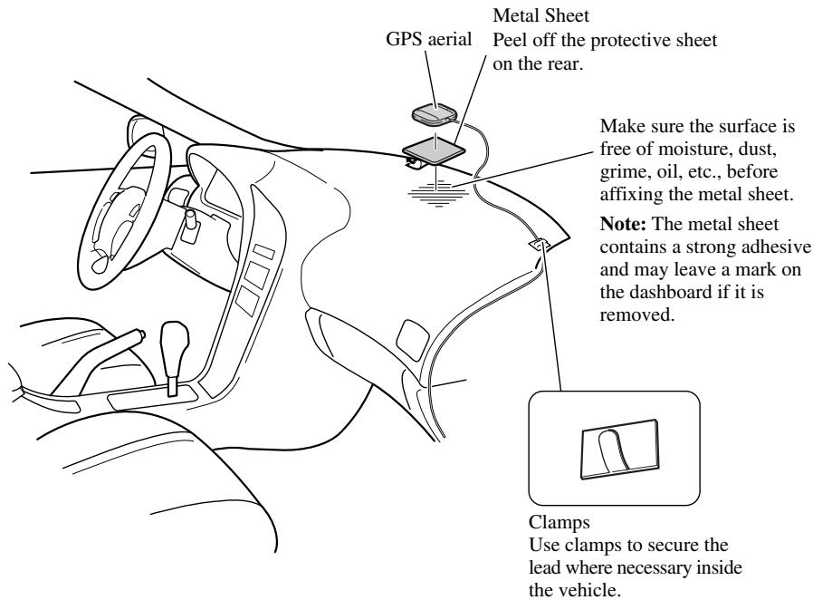
Note:
- When attaching the metal sheet, do not cut it into small pieces.
- Some models use window glass that does not allow signals from GPS satellites to pass through. On such models, install the GPS aerial on the outside of the vehicle.
When installing the aerial outside the vehicle (on the body)
Put the GPS aerial in a position as level as possible, such as on the roof or boot lid. (The GPS aerial is fastened with a magnet.)
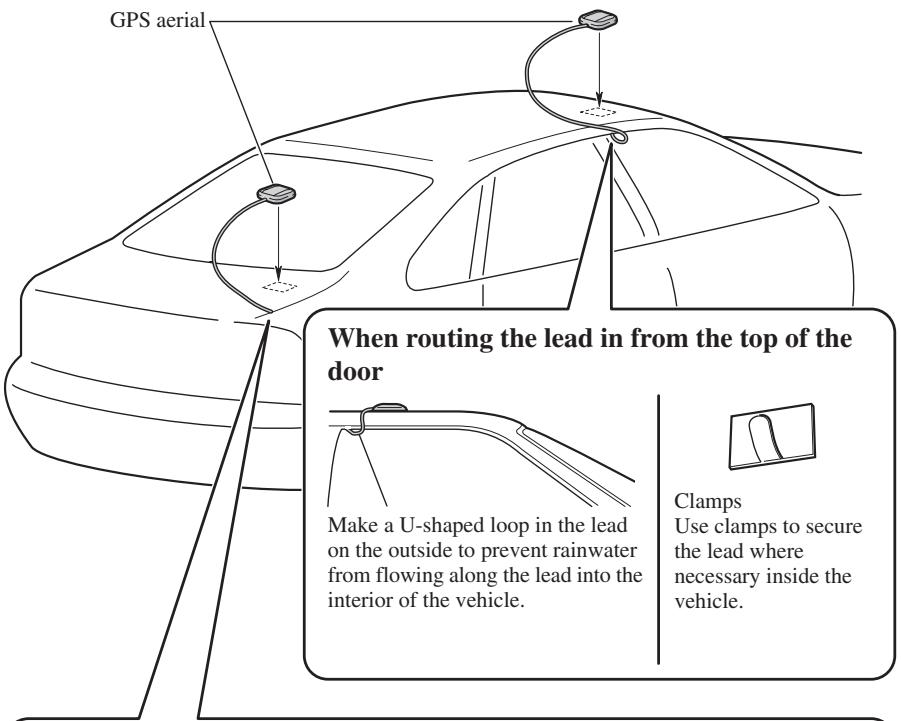
When routing the lead in from inside the boot
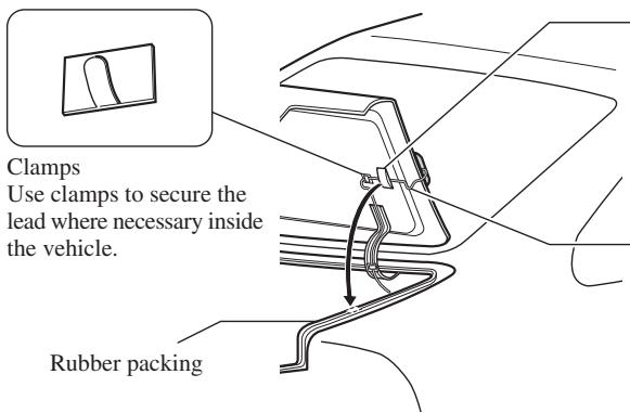
Waterproof pad Make sure the waterproof pad contacts the top of the rubber packing.
Make a U-shaped loop in the lead outside the rubber packing to prevent rainwater from flowing along the lead into the interior of the vehicle.
Parts supplied
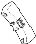
natural_image
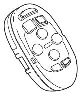
Line drawing of a remote control device with buttons and dials (no text or symbols)Steering remote control

Lithium battery (CR2032, 3 V)
natural_image
Line drawing of a mechanical component with no visible text or symbolsOuter holder

natural_image
Technical line drawing of a mechanical component with no visible text or symbolsInner holder

Belt

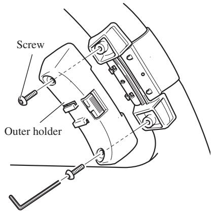
Screw

Hexagonal wrench
Loading the battery
Remove the battery cover, and insert a lithium (CR2032, 3V) battery. For details, see “Hardware Manual”.
WARNING
- Avoid installing this unit in such a location where the operation of safety devices such as airbags is prevented by this unit. Otherwise, there is a danger of a fatal accident.
- Avoid installing this unit in such a location where the operation of the steering wheel and the gearshift lever may be prevented. Otherwise, it may result in a traffic accident.
CAUTION
- Installation of this unit requires specialized skills and experience. Installation of this unit should be entrusted to a dealer from whom you purchased this unit.
- Install this unit using only the parts supplied with this unit. If other parts are used, this unit may be damaged or could dismount itself, which leads to an accident or trouble.
• Install this unit as required by this manual. Failure to do so may cause an accident. - Do not install this unit near the doors where rainwater is likely to be spilled on the unit. Incursion of water into the unit may cause smoke or fire.
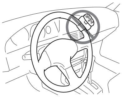
WARNING
- Fix this unit securely to the steering wheel with the belt attached to the unit. If this unit is loose, it disturbs driving stability, which may result in a traffic accident.
- Do not attach this unit to the outer circumference of the steering wheel. Otherwise, it disturbs driving stability, causing a traffic accident. Always attach this unit to the inner circumference of the steering wheel as shown.
Remote control handling notes
- Always keep the remote control protected from direct sunlight or high temperatures. Leaving the remote control in places exposed to direct sunlight or high temperatures for long periods of time may cause deformation, discolouration or malfunction.
- Replace the battery when the remote control's performance deteriorates.
- Do not install this unit in such a place as may obstruct the driver's view.
- Since interior layout differs depending on the type of vehicle, the ideal installation location for the unit also differs. When installing the unit, select a location that assures optimum transmission of signals from the unit to the display.
natural_image
Line drawing of a car steering wheel with a circular gauge showing 36% speed, no text or symbols present.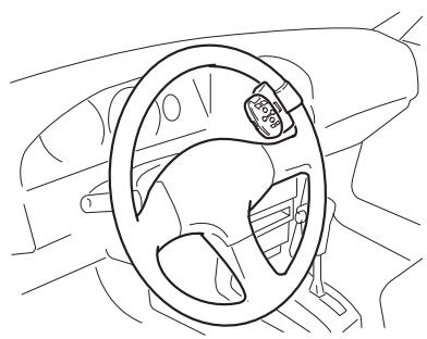
natural_image
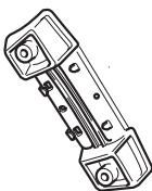
Line drawing of a car steering wheel with a circular component on the steering wheel (no text or symbols)Installing the holders and the steering remote control
Note:
- When the unit is installed on a right-hand-drive car, the horizontal positions are inverted.
1. Secure inner holder to the inner circumference of the steering wheel with belt.
- Fit the inner holder to the steering wheel so that the arrow-marked side faces the driver as shown below.
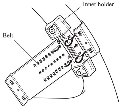
2. Cut the extra portion of the belt at the center of the inner holder.
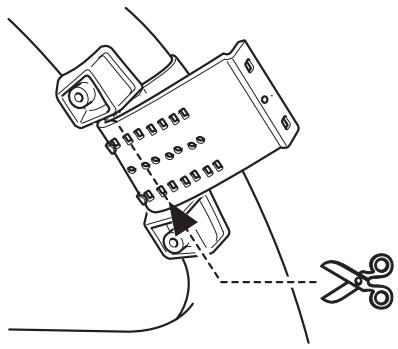
3. Install outer holder on the inner holder and secure with screws.
- Tighten the screws with the supplied hexagonal wrench.
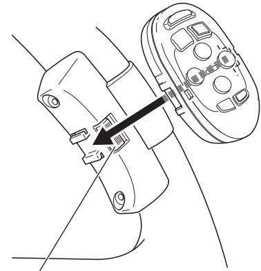
4. Install the remote control unit in the holder.
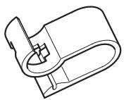
- When removing the remote control unit from the holder, move the corrugated release section toward the steering wheel and slide the remote control unit toward you.
natural_image
Technical line drawing of a mechanical component with a directional arrow indicating assembly or movement (no text or symbols present)Release Section
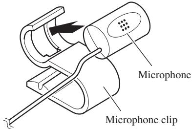
Installing the microphone
Installation notes
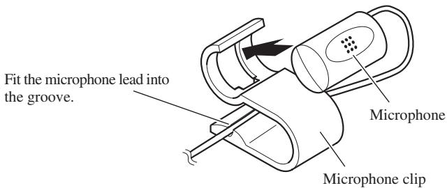
- Install the microphone in a position and orientation that will enable it to pick up the voice of the person operating the system.
Parts supplied
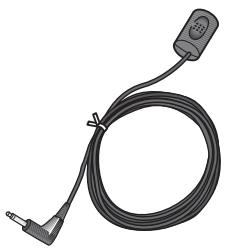
natural_image
Coiled black cable with a small electronic component attached (no text or symbols visible)Microphone

natural_image
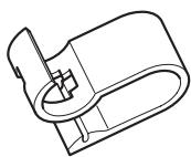
Technical line drawing of a mechanical component with no visible text or symbolsMicrophone clip

Double-sided tape (small)

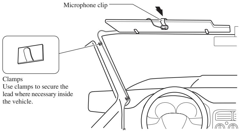
Clamp (5 pcs.)
When installing the microphone on the sun visor
1. Install the microphone on the microphone clip.
2. Install the microphone clip on the sun visor.
With the sun visor up, install the microphone clip. (Lowering the sun visor reduces the recognition rate for voice operations.)
When installing the microphone on the steering column
1. Install the microphone on the microphone clip.
2. Install the microphone clip on the steering column.
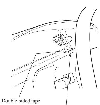
Install the microphone clip on the rear side of the steering column.

CAUTION
- It is extremely dangerous to allow the microphone lead to become wound around the steering column or gearstick. Be sure to install the unit in such a way that it will not obstruct driving.
1. Reconnecting the battery.
First, double-check that all connections are correct and that the unit is installed correctly. Reassemble all vehicle components that you previously removed. Then reconnect the negative (−) cable to the negative (−) terminal of the battery.
2. Start the engine.
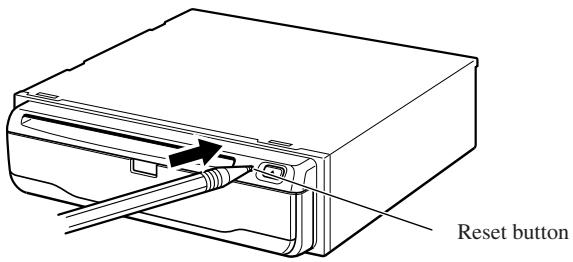
3. Press the reset button on the main unit.
Press the reset button on the main unit using a pointed object such as the point of a pen.
4. Set the navigation system.
Set the navigation system as explained in the “Operation Manual” or “Hardware Manual”.
natural_image
Illustration of a hand holding a battery with a switch and power plug (no text or symbols)Para impedir daños
Posición ACC
Sin posición ACC
Partes suministradas
natural_image
Illustration of a multi-pin electrical connector with wires and connectors (no text or symbols)natural_image
Line drawing of a cable with connectors (no text or symbols)natural_image
Technical line drawing of two mechanical clamping or fastening mechanisms (no text or symbols)natural_image
Diagram of a computer monitor front panel with various electronic components and indicators (no text or labels)natural_image
Simple line drawing of a rectangular device with a circular prohibition symbol below it (no text or labels)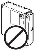
natural_image
Illustration of a hard drive with a prohibition symbol overlay (no text or symbols present)Partes suministradas

natural_image
Line drawing of a rectangular electronic device with a side panel and mounting bracket (no text or symbols)Unidad principal
Tornillo

natural_image
Technical line drawing of a rectangular electronic component with internal slots and mounting holes (no text or symbols)Soporte
natural_image
Isometric line drawing of a mechanical bracket or support structure (no text or symbols)natural_image
Simple line drawing of a rectangular object with a recessed top and side gap (no text or symbols)Marco

PRECAUCIÓN
natural_image
Diagram showing a rectangular object being processed into a partially assembled plastic component (no text or symbols present)Marco
natural_image
Pure mechanical component diagram without any text, numbers, or symbolsnatural_image
Illustration of hands using a tool to cut a rectangular object with an arrow indicating motion (no text or symbols present)natural_image
Pure diagram of circular components with downward arrows indicating motion or force, no text or symbols present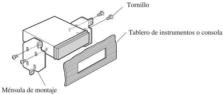
natural_image
Line drawing of a remote control device with buttons and dials (no text or symbols)natural_image
Line drawing of a mechanical component with no visible text or symbolsSujetador exterior

natural_image
Technical line drawing of a mechanical component with no visible text or symbolsSujetador interior

natural_image
Line drawing of a car steering wheel with a 35-degree angle indicator (no text or symbols beyond the angle marker)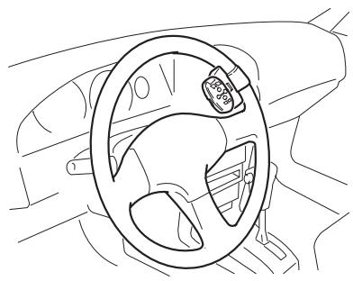
natural_image
Line drawing of a car steering wheel and dashboard (no text or symbols)natural_image
Technical line drawing of a mechanical assembly with a black arrow indicating a component (no text or symbols present)natural_image
Illustration of a black cable with a connector and terminal, no text or symbols presentMicrófono

natural_image
Technical line drawing of a mechanical component with no visible text or symbolsnatural_image
Illustration of a hand holding a battery with pins and a switch, no text or symbols presentACC-Stellung
Keine ACC-Stellung
Mitgelieferte Teile
natural_image
Illustration of a multi-wire electrical connector with wires and connectors (no text or symbols)Stromkabel
natural_image
Line drawing of a cable with two connectors (no text or symbols)26-poliges Kabel
natural_image
Line drawing of a car interior showing steering wheel and hand position (no text or symbols)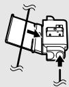
Anschlussmethode
natural_image
Line drawing of a hand using a pliers to handle a mechanical component (no text or symbols)
natural_image
Technical line drawing of two mechanical clamping or fastening mechanisms (no text or symbols)natural_image
Line drawing of a car front view showing grille and side panel (no text or symbols)natural_image
Diagram of a device rear panel with labeled components including buttons, indicators, and a fan (no text or symbols present)Hinweis:
natural_image
Two identical electronic devices with prohibition symbols, no text or labels presentMitgelieferte Teile

natural_image
Line drawing of a rectangular electronic device with a flat top and side connectors (no text or symbols)Navigationseinheit
Schraube
natural_image
Technical line drawing of a mechanical housing or enclosure with internal components (no text or symbols)Halterung
natural_image
Isometric line drawing of a 3D rectangular prism with a small square cutout on top (no text or symbols)natural_image
Simple line drawing of a rectangular object with a recessed top and side gap (no text or symbols)Rahmen

VORSICHTSMASSNAHMEN
natural_image
Isometric illustration of a rectangular electronic component with a recessed top (no text or symbols)natural_image
Diagram showing a rectangular block being inserted into a rectangular housing (no text or symbols present)Rahmen
natural_image
Pure mechanical component diagram without any text, numbers, or symbolsnatural_image
Illustration of hands using a tool to cut a rectangular object with an arrow indicating rotation (no text or symbols present)natural_image
Pure diagram of circular components with downward arrows, no text or symbols present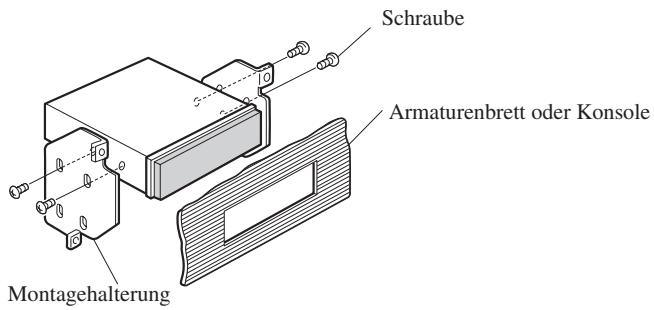
natural_image
Line drawing of a remote control device with buttons and dials (no text or symbols)natural_image
Line drawing of a mechanical component with no visible text or symbolsAußenhalter
natural_image
Technical line drawing of a mechanical component with no visible text or symbolsInnenhalter

natural_image
Line drawing of a car steering wheel with a circular indicator showing 30% speed limit (no text or symbols beyond the indicator)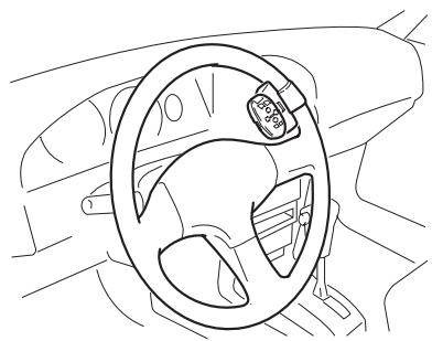
natural_image
Line drawing of a car steering wheel and dashboard (no text or symbols)natural_image
Technical line drawing of a mechanical assembly with a black arrow indicating a component (no text or symbols present)Freigabeteil
natural_image
Coiled black cable with a small electronic component attached (no text or symbols visible)Mikrofon
natural_image
Technical line drawing of a mechanical component with no visible text or symbolsMikrofonklemmhalter
EXPLICATIONS RELATIVES
À VOTRE UNITÉ DE NAVIGATION DVD
ET LES CONSERVER POUR VOUS Y
RÉFÉRER ÉVENTUELLEMENT
PAR LA SUITE 3
natural_image
Illustration of a hand holding a battery with a switch and power plug (no text or symbols)Position ACC
Pas de position ACC
Pièces fournies
natural_image
Line drawing of a multi-wire electrical connector with terminal blocks (no text or symbols)natural_image
Line drawing of a cable with two connectors (no text or symbols)Câble 26 broches
natural_image
Line drawing of a car front view showing grille and side panel (no text or symbols)natural_image
Diagram of a computer monitor rear panel with various electronic components and a pointer pointing to a device (no text or labels)natural_image
Two identical diagrams showing a device with a prohibition symbol, no text or labels present.Pièces fournies
natural_image
Line drawing of a rectangular electronic device with a side panel and mounting bracket (no text or symbols)Unité principale
Vis
natural_image
Technical line drawing of a rectangular electronic component with internal slots and mounting holes (no text or symbols)Support
natural_image
Isometric line drawing of a mechanical bracket or support structure (no text or symbols)clés d'extraction (2 piezas)

Baque en cautchouc

Vis de serrage
(5 × 6 mm)
(4 pièces)

Vis à tête plate
(5 × 6 mm)
(4 pièces)
natural_image
Simple line drawing of a rectangular object with a recessed top and side gap (no text or symbols)Cadre

ATTENTION
natural_image
Pure diagram of circular components with downward arrows, no text or symbols present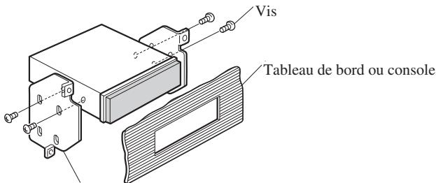
natural_image
Line drawing of a remote control device with buttons and dials (no text or symbols)natural_image
Line drawing of a mechanical component with no visible text or symbolsSupport externe
natural_image
Technical line drawing of a mechanical component with no visible text or symbolsSupport interne
Courroie

Vis

Clé à six pans
Insertion une pile
natural_image
Line drawing of a car steering wheel with a circular annotation highlighting the 85% threshold (no text or symbols on the diagram itself)
natural_image
Line drawing of a car steering wheel and dashboard (no text or symbols)natural_image
Technical line drawing of a mechanical assembly with a black arrow indicating a component (no text or symbols present)natural_image
Illustration of a hand holding a battery with pins and a switch, no text or symbols presentPer evitare danni
Posizione ACC

natural_image
Line drawing of a multi-wire electrical connector with terminal blocks (no text or symbols)natural_image
Line drawing of a cable with two connectors (no text or symbols)Cavo a 26 pin
natural_image
Diagram of a computer chassis with labeled components (no text or symbols)Nota:
(INGRESSO SEGNALE RETROMARCIA)
natural_image
Line drawing of a car front view showing grille and side panels (no text or symbols)natural_image
Two identical electronic devices with prohibition symbols, no text or labels presentPezzi in dotazione

natural_image
Line drawing of a rectangular electronic device with a side panel and mounting bracket (no text or symbols)Unità principale
Vite

natural_image
Isometric line drawing of a rectangular electronic component with internal slots and mounting holes (no text or symbols)Supporto

natural_image
Isometric line drawing of a mechanical bracket or support structure (no text or symbols)Chiavette (2 pz.)

Boccola di gomma

Vite ad incastro
(5 × 6 mm)
(4 pz.)
natural_image
Simple line drawing of a rectangular object with a recessed top and side gap (no text or symbols)Cornice

PRECAUZIONE
natural_image
Technical illustration of a mechanical assembly with a tool interacting with a workpiece (no text or symbols present)natural_image
Pure diagram of mechanical components with arrows indicating motion or force direction (no text or symbols)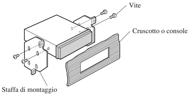
natural_image
Line drawing of a remote control device with buttons and dials (no text or symbols)Telecomando al volante

Batteria al litio (CR2032, 3V)

natural_image
Line drawing of a mechanical component with no visible text or symbolsSupporto externo

natural_image
Technical line drawing of a mechanical component with no visible text or symbolsSupporto interno

natural_image
Line drawing of a car steering wheel with a circular indicator showing 30% speed limit (no text or symbols beyond the indicator)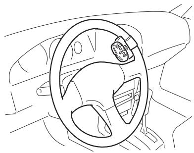
natural_image
Line drawing of a car steering wheel and dashboard (no text or symbols)natural_image
Technical line drawing of a mechanical assembly with scissors and fasteners (no text or symbols)natural_image
Technical line drawing of a mechanical component with an arrow indicating assembly or adjustment (no text or symbols present)natural_image
Coiled black cable with a small sensor or probe attached, no visible text or symbolsMicrofono
natural_image
Technical line drawing of a mechanical component with no visible text or symbolsGancio microfono
natural_image
Illustration of a hand holding a battery with a switch and power plug (no text or symbols)ACC stand
Geen ACC stand
natural_image
Illustration of a multi-pin electrical connector with coiled wires and connectors (no text or symbols)Stroomsnoer
Stekker
natural_image
Line drawing of a cable with a connector (no text or symbols)26-pins-kabel
Roze (RIJSNELHEIDSSIGNAAL)
Zwart, oranje/wit, rood, geel
Zie blz 11.
Geel/zwart
natural_image
Line drawing of a car front view showing grille and side brackets (no text or symbols)natural_image
Simple line drawing of a rectangular device with a prohibition symbol (no text or labels)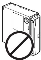
natural_image
Illustration of a hard drive with a prohibition symbol (no text or labels)natural_image
Line drawing of a rectangular electronic device with a side panel and mounting bracket (no text or symbols)Hoofdapparaat
Schroef

natural_image
Isometric line drawing of a rectangular electronic component with internal slots and mounting holes (no text or symbols)Houder

natural_image
Isometric line drawing of a mechanical bracket or support structure (no text or symbols)natural_image
Simple line drawing of a rectangular object with a recessed top and side gap (no text or symbols)Frame

BELANGRIJK
natural_image
Technical line drawing of a mechanical component with a magnified inset showing internal features (no text or symbols)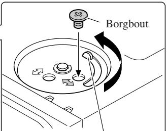
natural_image
Diagram showing a rectangular block being inserted into a plastic housing (no text or symbols present)Frame
natural_image
Pure mechanical component diagram without any text, numbers, or symbolsnatural_image
Illustration of hands using a tool to cut a rectangular object with an arrow indicating rotation (no text or symbols present)natural_image
Pure diagram of mechanical components with arrows indicating motion or force direction (no text or symbols)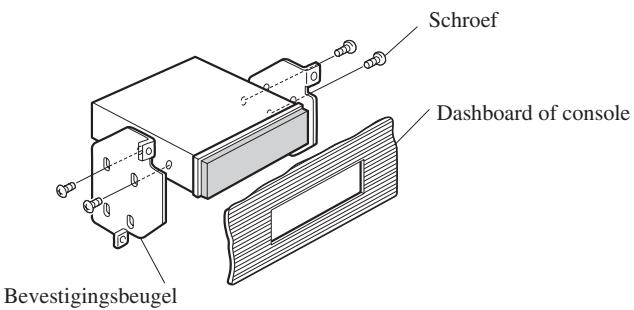

BELANGRIJK
natural_image
Line drawing of a remote control device with buttons and dials (no text or symbols)natural_image
Line drawing of a mechanical component with no visible text or symbolsBuitenste houder
natural_image
Technical line drawing of a mechanical component with no visible text or symbolsBinnenste houder
Riem

Schroef
natural_image
Line drawing of a car steering wheel with a 35-degree angle indicator (no text or symbols beyond the angle marker)
natural_image
Line drawing of a car steering wheel and dashboard (no text or symbols)natural_image
Technical line drawing of a mechanical component with a black arrow indicating a joint or connection (no text or symbols present)PIONEER ELECTRONICS (USA) INC.
P.O. Box 1540, Long Beach, California 90801-1540, U.S.A.
TEL: (800) 421-1404
PIONEER EUROPE NV
Haven 1087, Keetberglaan 1, B-9120 Melsele, Belgium
TEL: (0) 3/570.05.11
PIONEER ELECTRONICS ASIACENTRE PTE. LTD.
253 Alexandra Road, #04-01, Singapore 159936
TEL: 65-6472-1111
PIONEER ELECTRONICS AUSTRALIA PTY. LTD.
178-184 Boundary Road, Braeside, Victoria 3195, Australia
TEL: (03) 9586-6300
PIONEER ELECTRONICS OF CANADA, INC.
300 Allstate Parkway, Markham, Ontario L3R OP2, Canada
TEL: (905) 479-4411
PIONEER ELECTRONICS DE MEXICO, S.A. de C.V.
Blvd.Manuel Avila Camacho 138 10 piso
Col.Lomas de Chapultepec, Mexico, D.F. 11000
TEL:55-9178-4270
先鋒股份有限公司
總公司:台北市中山北路二段44號13樓
電話: (02) 2521-3588
先鋒電子(中國)有限公司
Published by Pioneer Corporation.
Copyright © 2003 by Pioneer Corporation.
All rights reserved.
Publication de Pioneer Corporation.
Copyright © 2003 Pioneer Corporation.