
AVIC-F910BT - GPS Navigation System PIONEER - Free user manual and instructions
Find the device manual for free AVIC-F910BT PIONEER in PDF.
| Product type | GPS navigation system for vehicle |
| Brand | PIONEER |
| Model | AVIC-F910BT |
| Power supply | 12 V DC (vehicle battery) |
| Main functions | GPS navigation, audio/video, hands-free Bluetooth, rear view camera, AV inputs, rear video output |
| Antenna | External GPS antenna supplied with metal plate |
| Microphone | External microphone supplied with clip and adhesive tape |
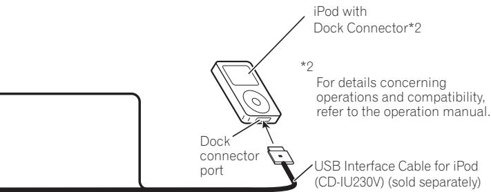
| Connectivity | Bluetooth, USB (via optional CD-IU230V cable), AV inputs (RCA), rear video output |
| Audio outputs | Front/rear speakers (4 Ω to 8 Ω, max power 50 W), RCA output for subwoofer |
| Video inputs | AV1 input, AV2 input (composite), rear view camera input |
| Protections | Appropriate rated fuse, short-circuit protection circuit |
| Installation | Connection to parking brake (light green wire), speed signal, reverse signal; can be installed in car radio drawer or using the supplied bracket |
| Accessories provided | Power cord, connectors, extension cables (reverse signal, speed signal), GPS antenna, microphone, bracket, screws, trim ring |
| Operating temperature | Not specified, avoid high temperatures and humidity |
| Maintenance | Clean with a soft dry cloth; do not use solvents |
Frequently Asked Questions - AVIC-F910BT PIONEER
User questions about AVIC-F910BT PIONEER
0 question about this device. Answer the ones you know or ask your own.
Ask a new question about this device
Download the instructions for your GPS Navigation System in PDF format for free! Find your manual AVIC-F910BT - PIONEER and take your electronic device back in hand. On this page are published all the documents necessary for the use of your device. AVIC-F910BT by PIONEER.
USER MANUAL AVIC-F910BT PIONEER
INSTALLATION MANUAL MANUEL D'INSTALLATION
ABOUT YOUR NEW NAVIGATION SYSTEM AND THIS MANUAL 3
12 IMPORTANT SAFEGUARDS
PLEASE READ ALL OF THESE INSTRUCTIONS REGARDING YOUR NAVIGATION SYSTEM AND RETAIN THEM FOR FUTURE REFERENCE 4
03 Connecting the System
Precautions before connecting the system 5
Before installing this product 6
To prevent damage 6
- Notice for the blue lead 6
- Notice for the blue/white lead 7
Parts supplied 7
Connecting the system 8
Connecting the power cord (1) 10
Connecting the power cord (2) 12
When connecting to separately sold power amp 14
When connecting a rear view camera 16
When connecting the rear display 17
- When using a rear display connected to rear video output 17
When connecting the external video component 17
-Using"AV1Input"(AV1) 17
-Using "AV2 Input" (AV2) 18
04 Installation
Precautions before installation 19
To guard against electromagnetic interference 19
Before installing 20
Installing this navigation system 20
- Installation notes 20
-
Parts supplied 21
-
Before installing this navigation unit 22
Installation with the holder and side bracket 22
Installation using the screw holes on the side of the navigation unit 23
Installing the GPS aerial 24
Installation notes 24
- Parts supplied 24
- When installing the aerial inside the vehicle (on the dashboard or rear shelf) 25
Installing the microphone 26
- Parts supplied 26
- Mounting on the sun visor 26
- Installation on the steering column 27
- Adjusting the microphone angle 28
05 After Installation
After Installing this navigation system 29
ABOUT YOUR NEW NAVIGATION SYSTEM AND THIS MANUAL
- The navigation features of this product (and rear view camera option if purchased) are intended solely to aid you in the operation of your vehicle. It is not a substitute for your attentiveness, judgement and care when driving.
- Never use this navigation system to route to hospitals, police stations, or similar facilities in an emergency. Please call the appropriate emergency number.
- Do not operate this navigation system (or the rear view camera option if purchased) if doing so in any way will divert your attention from the safe operation of your vehicle. Traffic restrictions and advisories currently in force should always take precedence over guidance given by this product. Always obey current traffic restrictions, even if this product provides contrary advice.
- This manual explains how to install this navigation system in your vehicle. Operation of this navigation system is explained in the separate manuals for the navigation system.
- Do not install this product where it may (i) obstruct the driver's vision, (ii) impair the performance of any of the vehicle's operating systems of safety features, including airbags, hazard lamp buttons or (iii) impair the driver's ability to safely operate the vehicle. In some cases, it may not be possible to install this product because of the vehicle type or the shape of the vehicle interior.
WARNING
Pioneer does not recommend that you install your navigation system yourself. We recommend that only authorised Pioneer service personnel, who have special training and experience in mobile electronics, set up and install this product. NEVER SERVICE THIS PRODUCT YOURSELF. Installing or servicing this product and its connecting cables may expose you to the risk of electric shock or other hazards, and can cause damage to the navigation system that is not covered by warranty.
PLEASE READ ALL OF THESE INSTRUCTIONS REGARDING YOUR NAVIGATION SYSTEM AND RETAIN THEM FOR FUTURE REFERENCE
1 Read this manual fully and carefully before installing your navigation system.
2 Keep this manual handy for future reference.
3 Pay close attention to all warnings in this manual and follow the instructions carefully.
4 This navigation system may in certain circumstances display erroneous information regarding the position of your vehicle, the distance of objects shown on the screen, and compass directions. In addition, the system has certain limitations, including the inability to identify one-way streets, temporary traffic restrictions and potentially unsafe driving areas. Please exercise your own judgement in the light of actual driving conditions.
5 As with any accessory in your vehicle's interior, the navigation system should not divert your attention from the safe operation of your vehicle. If you experience difficulty in operating the system or reading the display, please make adjustments while safely parked.
6 Please remember to wear your seat belt at all times while operating your vehicle. If you are ever in an accident, your injuries can be con
siderably more severe if your seat belt is not properly fastened.
7 In certain countries, laws may restrict the placement and use of navigation systems in your vehicle. Please comply with all applicable laws and regulations in the installation and operation of your navigation system.
Precautions before connecting the system
CAUTION
- If you decide to perform the installation yourself, and have special training and experience in the mobile electronics installations, please carefully follow all of the steps in the installation manual.
- Secure all wiring with cable clamps or electrical tape. Do not allow any bare wiring to remain exposed.
- Do not directly connect the yellow lead of this product to the vehicle battery. If the lead is directly connected to the battery, engine vibration may eventually cause the insulation to fail at the point where the wire passes from the passenger compartment into the engine compartment. If the yellow lead's insulation tears as a result of contact with metal parts, short-circuiting can occur, resulting in considerable danger.
- It is extremely dangerous to allow the cables to become wound around the steering column or gearstick. Be sure to install this product, its cables, and wiring away in such a way that they will not obstruct or hinder driving.
Make sure that the cables and wires are routed and secured so they will not interfere with or become caught in any of the vehicle's moving parts, especially the steering wheel, gearstick, handbrake, sliding seat tracks, doors, or any of the vehicle's controls. - Do not route wires where they will be exposed to high temperatures. If the insulation heats up, wires may become damaged, resulting in a short circuit or malfunction and permanent damage to the product.
-
Do not cut the GPS aerial cable to shorten it or use an extension to make it longer. Altering the aerial cable could result in a short circuit or malfunction.
-
Do not shorten any leads. If you do, the protection circuit (fuse holder, fuse resistor or filter, etc.) may fail to work properly.
- Never feed power to other electronic products by cutting the insulation of the power supply lead of the navigation system and tapping into the lead. The current capacity of the lead will be exceeded, causing overheating.
- The black lead is earth. Please earth this lead separately from the earth of high-current products such as power amps. Do not earth more than one product together with the earth from another product. For example, you must separately earth any amp unit away from the earth of this navigation system. Connecting earths togethe can cause a fire and/or damage the products if their earths became detached.
Before installing this product
- This product is for vehicles with a 12-volt battery and negative earthing. Check the battery voltage of your vehicle before installation.
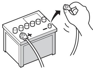
- To avoid shorts in the electrical system, be sure to disconnect the (-) battery cable before beginning installation.

To prevent damage

WARNING
-
When replacing the fuse, be sure to only use a fuse of the rating prescribed on this product.
-
When disconnecting a connector, pull the connector itself. Do not pull the lead, as you may pull it out of the connector.
- This product cannot be installed in a vehicle without ACC (accessory) position on the ignition switch.
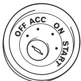
ACC position
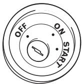
No ACC position
-
To avoid short-circuiting, cover the disconnected lead with insulating tape. It is especially important to insulate all unused speaker leads, which if left uncovered may cause a short circuit.
-
Attach the connectors of the same colour to the corresponding coloured port, i.e., blue connector to the blue port, black to black, etc.
Refer to the owner's manual for details on connecting the power amp and other units, then make connections accordingly. - Since a unique BPTL circuit is employed, do not directly earth the side of the speaker lead or connect the sides of the speaker leads together. Be sure to connect the side of the speaker lead to the side of the speaker lead on this navigation system.
- If the RCA pin jack on this product will not be used, do not remove the caps attached to the end of the connector.
- Never connect speakers with an output rating of less than 50 W channel or impedance outside of the 4 ohms to 8 ohms specifications to your navigation system. Connecting speakers with output and/or impedance values other than those noted here may result in the speakers catching fire, emitting smoke, or becoming damaged.
Notice for the blue lead
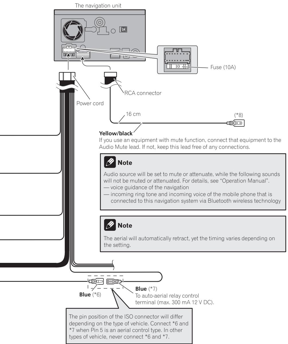
- A signal is output through the blue lead to control the aerial of your vehicle. The timing varies depending on the setting. (For more detailed information on changing [Ant CTRL] mode, refer to "Operation Manual".)
- When [Ant CTRL] mode is set to [Radio], the vehicle's aerial can be stowed or turned off by following the instructions below.
Change the source from radio (MW/LW or FM) to another source.
Turn the source off
Turn off the ignition switch (ACC OFF)
- If [Ant CTRL] mode is set to [Power], the vehicle's aerial can be stowed or turned off only when the ignition switch is turned off (ACC OFF).
Connecting the System
- Do not connect this lead to the system control terminal of external power amps.
- Be sure not to use this lead as the power supply lead for the auto-aerial or aerial booster. Such connection could cause excessive current drain and malfunction.
Notice for the blue/white lead
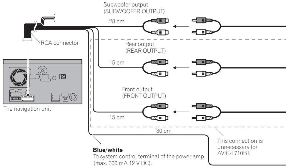
- When the ignition switch is turned on (ACC ON), a control signal is output through the blue/white lead. Connect to an external power amp's system remote control terminal (max. 300 mA 12 V DC). The control signal is output through the blue/white lead, even if the audio source is switched off.
- Do not connect this lead to the auto-aerial relay control terminal or the aerial booster power control terminal.
- Be sure not to use this lead as the power supply lead for the external power amps. Such connection could cause excessive current drain and malfunction.
Extension lead* (for speed signal)
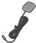
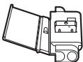
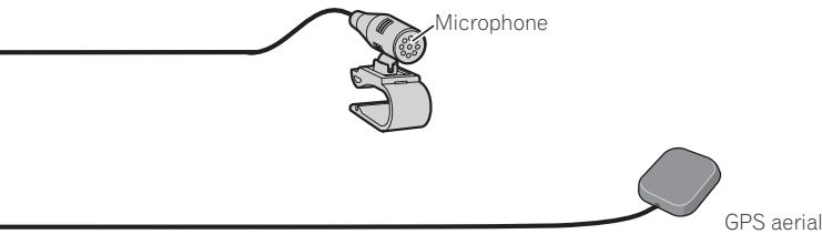
GPS aerial
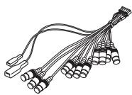
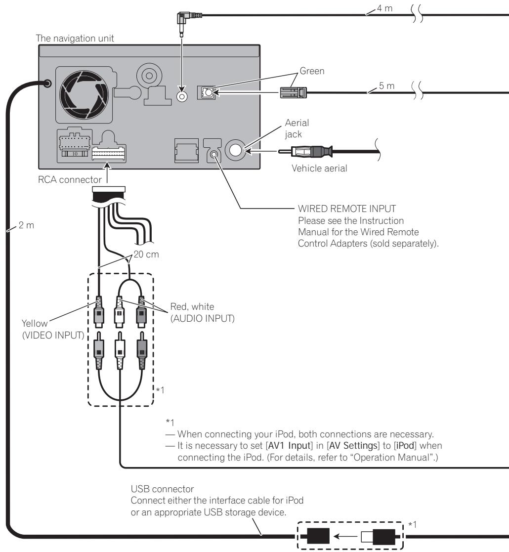
RCA connector
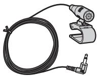

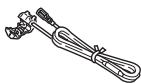
Microphone
Parts supplied
Parts marked (^*) are not supplied with AVICF710BT.

The navigation unit
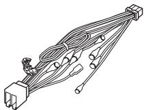
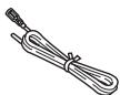
Power cord
Connector*
Extension lead (for reverse signal)
Connecting the system
Connecting the System

WARNING
- To avoid the risk of accident and the potential violation of applicable laws, this product should never be used while the vehicle is being driven except for navigation purposes. And, also Rear Displays should not be in a location where it is a visible distraction to the driver.
- In some countries, the viewing of images on a display inside a vehicle even by persons other than the driver may be illegal. Where such regulations apply they must be obeyed and this product's video source should not be used.

Connecting the power cord (1)

Note
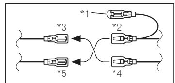
Depending on the kind of vehicle, the function of 3 and 5 may be different. In this case, be sure to connect 2 to 5 and 4 to 3.

Notes
- When a subwoofer (*9) is connected to this navigation system instead of a rear speaker, change the rear output setting in the Initial Setting. (Refer to "Operation Manual") The subwoofer output of this navigation system is monaural.
- When using a subwoofer of 70W(2) , be sure to connect with violet and violet/black leads of this navigation system. Do not connect anything with green and green/black leads.
Cap (*1)
When not using this terminal, do not remove the cap.
Connect leads of the same colour to each other.

Yellow (^*3) Back-up (or accesso


Yellow (*2)
To terminal always supplied with power regardless of ignition switch position.

Red (*5)
Accessory (or back-up)
Red (*4)
To electric terminal controlled by ignition switch (12 V DC) ON/OFF.
Orange/white
To lighting switch terminal.
Black (earth)
To vehicle (metal) body.
ISO connector
Yellow/black
If the vehicle can send a mute signal to this terminal, the mute function can be activated on this navigation system when the terminal is connected to *8.

Note
In some vehicles, the ISO connector may be divided into two. In this case, be sure to connect to both connectors.
Speaker leads
White: Front left
White/black: Front left
Grey: Front right
Grey/black: Front right
Green: Rear left or Subwoofer (*9)
Green/black: Rear left or Subwoofer (*9)
Violet: Rear right or Subwoofer (^*9)
Violet/black: Rear right or Subwoofer (*9)
Connecting the System

Connecting the power cord (2)
Speed detection circuit lead
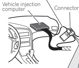
Connection method

Pass the extension cord and the lead for the speed detection circuit through this hole.

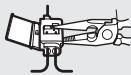
Clamp firmly with needle-nosed pliers.

Close the cover.
3m
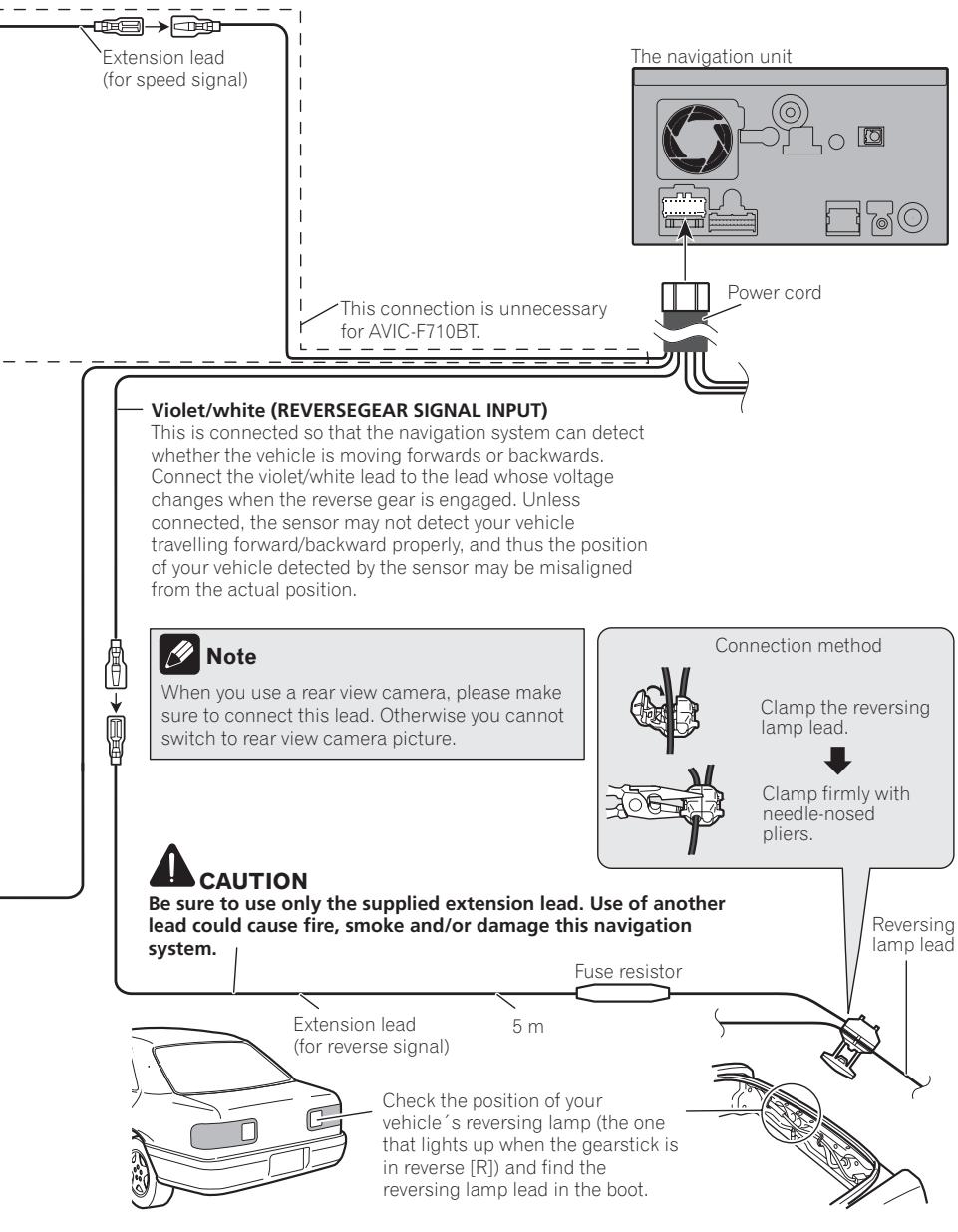
Pink (CAR SPEED SIGNAL INPUT)
This connection is unnecessary for AVIC-F710BT.
The mobile navigation system is connected here to detect the distance the vehicle travels. Always connect the vehicle's speed detection circuit. Failure to make this connection will increase errors in the location display.

WARNING
IMPROPER CONNECTION MAY RESULT IN SERIOUS DAMAGE OR INJURY INCLUDING ELECTRICAL SHOCK, AND INTERFERENCE WITH THE OPERATION OF THE VEHICLE'S ANTILOCK BRAKING SYSTEM, AUTOMATIC GEARBOX AND SPEEDOMETER INDICATION.

CAUTION
It is strongly suggested that the speed pulse wire be connected for accuracy of navigation and better performance.

Note
The position of the speed detection circuit and the position of the handbrake switch vary depending on the vehicle model. For details, consult your authorised Pioneer dealer or an installation professional.
Light green
Used to detect the ON/OFF status of the handbrake. This lead must be connected to the power supply side of the handbrake switch.
If this connection is made incorrectly or omitted, certain functions of your navigation system will be unusable.

WARNING
LIGHT GREEN LEAD AT POWER CONNECTOR IS DESIGNED TO DETECT PARKED STATUS AND MUST BE CONNECTED TO THE POWER SUPPLY SIDE OF THE HANDBRAKE SWITCH. IMPROPER CONNECTION OR USE OF THIS LEAD MAY VIOLATE APPLICABLE LAW AND MAY RESULT IN SERIOUS INJURY OR DAMAGE.
Connection method

Clamp the handbrake switch power supply side lead.
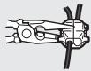
Clamp firmly with needle-nosed pliers.
Power supply side
Earth side
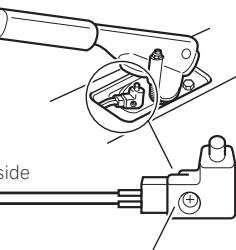
Handbrake switch
Connecting the System

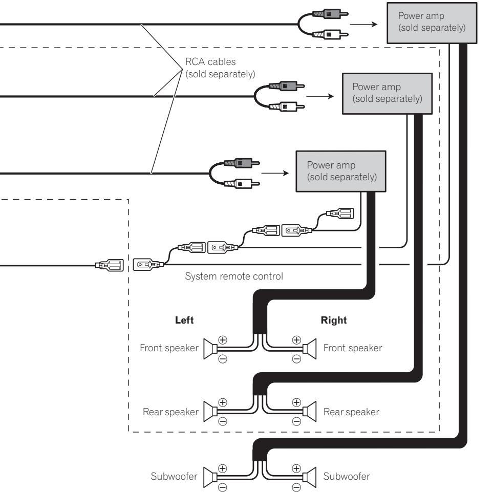
When connecting to separately sold power amp
Connecting the System

Note
You can change the RCA output of the subwoofer depending on your subwoofer system. (Refer to "Operation Manual".)

When connecting a rear view camera
When this product is used with a rear view camera, it is possible to automatically switch from the video to rear view image when the gearstick is moved to REVERSE (R). Rear View mode also allows you to check what is behind you while driving.

WARNING
USE INPUT ONLY FOR REVERSE OR MIRROR IMAGE REAR VIEW CAMERA. OTHER USE MAY RESULT IN INJURY OR DAMAGE.

CAUTION
- The screen image may appear reversed.
- The rear view camera function is to use this product as an aid to keep an eye on trailers, or backing into a tight parking spot. Do not use this function for entertainment purposes.
- The object in rear view may appear closer or more distant than in reality.
- Please note that the edges of the rear view camera images may differ slightly according to whether full screen images are displayed when backing, and whether the images are used for checking the rear when the vehicle is moving forward.

CAUTION
Be sure to use only the supplied extension lead. Use of another lead could cause fire, smoke and/or damage this navigation system.
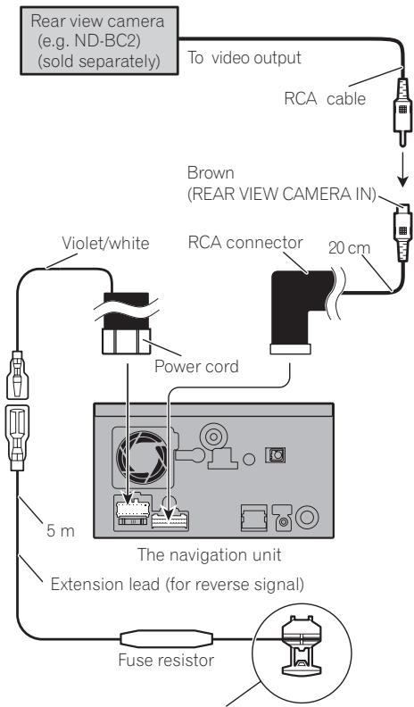
For more details about the wiring, refer to Connecting the power cord (2) on page 12.

Notes
- It is necessary to set [Back Camera] in [System Settings] to [On] when connecting the rear view camera. (For details, refer to "Operation Manual".)
- Connect to the rear view camera. Do not connect to any other equipment.

When connecting the rear display
This connection is unnecessary for AVIC-F710BT.

When using a rear display connected to rear video output
WARNING
NEVER install the rear display in a location that enables the driver to watch the video source while driving.
This navigation system's rear video output is for connection of a display to enable passengers in the rear seats to watch the video source.
When connecting the external video component Using "AV1 Input" (AV1)
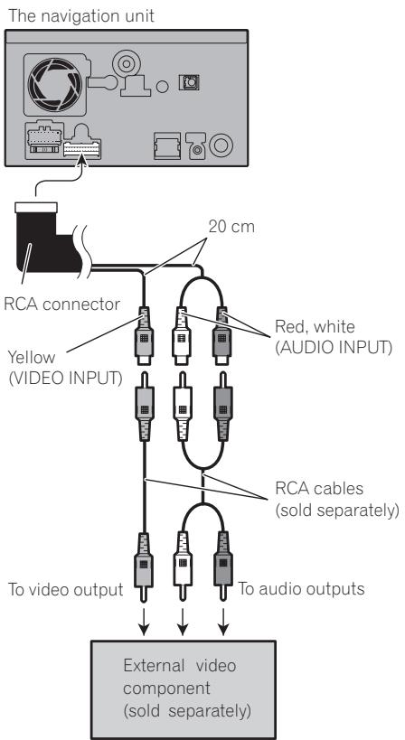
- It is necessary to set [AV1 Input] in [AV Settings] to [Video] when connecting the external video component. (For details, refer to "Operation Manual".)
Using "AV2 Input" (AV2)
The navigation unit
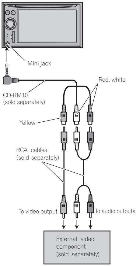
- It is necessary to set [AV2 Input] in [AV Settings] to [Video] when connecting the external video component. (For details, refer to "Operation Manual".)

CAUTION
Be sure to use a CD-RM10 (sold separately) for wiring. If you use other cables, there is a case where wiring position differs, images and sounds may be disturbed.
| OK | ∅ |
| L V G R | L R G V |
L:Leftaudio(White)
R:Rightaudio(Red)
V: Video (Yellow)
G:Earth

Precautions before installation
CAUTION
- Never install this product in places where, or in a manner that:
It could injure the driver or passengers if the vehicle stops suddenly.
It may interfere with the driver's operation of the vehicle, such as on the floor in front of the driver's seat, or close to the steering wheel or gearstick.
- Make sure there is nothing behind the dashboard or panelling when drilling holes in them. Be careful not to damage fuel lines, brake lines, electronic components, communication wires or power cables.
- When using screws, do not allow them to come into contact with any electrical lead. Vibration may damage wires or insulation, leading to a short circuit or other damage to the vehicle.
- To ensure proper installation, use the supplied parts in the manner specified. If any parts other than the supplied ones are used, they may damage internal parts of this product or they may work loose and the product may become detached.
- It is extremely dangerous to allow the cables to become wound around the steering column or gearstick. Be sure to install this product, its cables, and wiring away in such a way that they will not obstruct or hinder driving.
Make sure that leads cannot get caught in a door or the sliding mechanism of a seat, resulting in a short circuit. - Please confirm the proper function of your vehicle's other equipment following installation of the navigation system.
Certain government laws may prohibit or restrict the placement and use of this system in your vehicle. Please comply with all applicable laws and regulations re
garding the use, installation and operation of your navigation system.
- Do not install this navigation system where it may (i) obstruct the driver's vision, (ii) impair the performance of any of the vehicle's operating systems or safety features, including airbags, hazard lamp buttons or (iii) impair the driver's ability to safely operate the vehicle.
- Install the navigation system between the driver's seat and front passenger seat so that it will not be hit by the driver or passenger if the vehicle stops quickly.
- Never install the navigation system in front of or next to the place in the dash, door, or pillar from which one of your vehicle's airbags would deploy. Please refer to your vehicle's owner's manual for reference to the deployment area of the frontal airbags.
- Do not install the navigation system in a place where it will impair the performance of any of the vehicle's operating systems, including airbags and headrests.
To guard against electromagnetic interference
In order to prevent interference, set the following items as far as possible from this navigation system, other cables or leads:
TV aerial and aerial lead
FM, MW/LW aerial and its lead
GPS aerial and its lead
In addition you should lay or route each aerial lead as far as possible from other aerial leads. Do not bind them together, lay or route them together, or cross them. Such electromagnetic noise will increase the potential for errors in the location display.
Before installing
- Consult with your nearest dealer if installation requires the drilling of holes or other modifications of the vehicle.
- Before making a final installation of this product, temporarily connect the wiring to confirm that the connections are correct and the system works properly.
Installing this navigation system
Installation notes
- Do not install this navigation system in places where it may become subject to high temperatures or humidity, such as:
Places close to a heater, vent or air conditioner.
Places exposed to direct sunlight, such as on top of the dashboard.
Places that may be splashed by rain, for example close to the door. - Install this navigation system in an area strong enough to bear its weight. Choose a position where this navigation system can be firmly installed, and install it securely. If this navigation system is not securely installed, the current location of the vehicle cannot be displayed correctly.
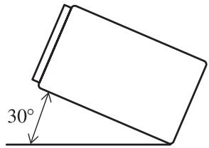
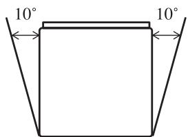
- Install the navigation unit horizontally on a surface within 0 degrees to 30 degrees tolerance (within 10 degrees to the left or right). Improper installation of the unit with the surface tilted more than these tolerances increases the potential for errors in the location display, and might otherwise cause reduced display performance.
- When installing, to ensure proper heat dispersal when using this unit, make sure you leave ample space behind the rear panel and wrap any loose cables so they are not blocking the vents.
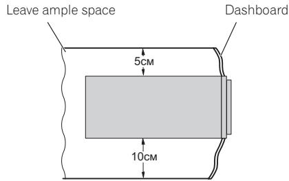
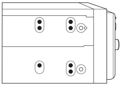
- The cords must not cover up the area shown in the figure below. This is necessary to allow the amps and navigation mechanism to dissipate heat.
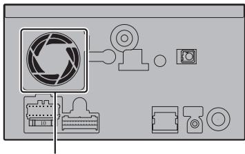
Do not cover this area.
- The semiconductor laser will be damaged if it overheats, so don't install the navigation unit anywhere hot—for instance, near a heater outlet.
Parts supplied
Parts marked () are pre-installed.
The navigation unit
Holder*
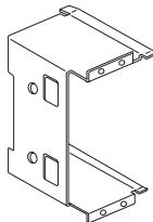
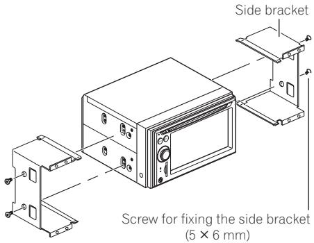
Side bracket* (2 pcs.)

Binding screw
(5 mm × 6 mm)
(8 pcs.)

Flush surface screw
(5 mm × 6 mm)
(4 pcs.)

Screw*
(3 mm × 6 mm)
(8 pcs.)


Screw for fixing the side bracket*
(5 mm × 6 mm)
(4 pcs.)
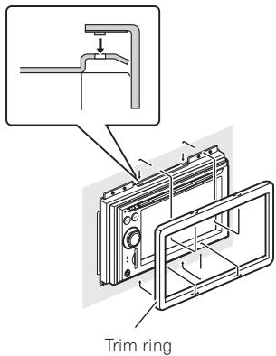
Trim ring
Before installing this navigation unit
- Remove the holder.
Loosen the screws (3mm× 6mm) to remove the holder.
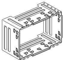
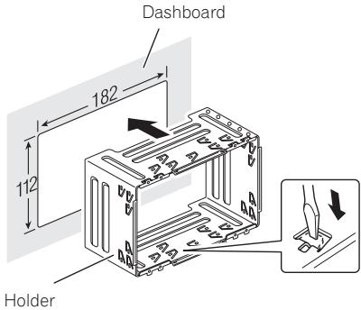
Installation with the holder and side bracket
1 Install the holder into the dashboard.
After inserting the holder into the dashboard, select and bend the tabs appropriate to the thickness of the dashboard material. (Install this navigation unit as firmly as possible using the top and bottom tabs. To secure this navigation unit, bend the tabs 90 degrees.)
2 Install this navigation unit and fasten the screws.
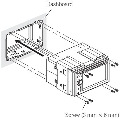
3 Attach the trim ring.
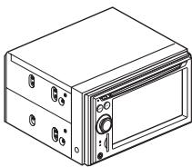
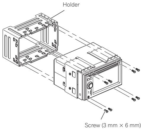
Installation using the screw holes on the side of the navigation unit
1 Remove the side brackets.
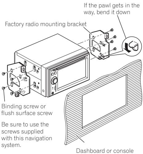
2 Fastening the navigation unit to the factory radio-mounting bracket.
Position the navigation unit so that its screw holes are aligned with the screw holes of the bracket, and tighten the screws at 3 or 4 locations on each side.

Installing the GPS aerial

CAUTION
Do not cut the GPS aerial lead to shorten it or use an extension to make it longer. Altering the aerial cable could result in a short circuit or malfunction and permanent damage to the navigation system.
Installation notes
- The aerial should be installed on a level surface where radio waves will be blocked as little as possible. Radio waves cannot be received by the aerial if reception from the satellite is blocked.
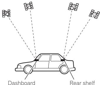
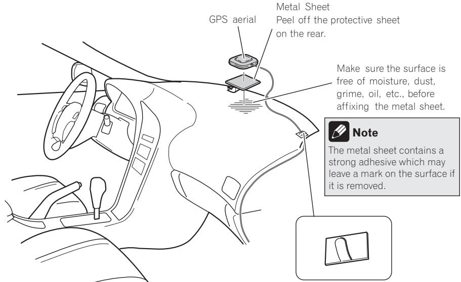
- When installing the GPS aerial inside the vehicle, be sure to use the metal sheet provided with your system. If this is not used, the reception sensitivity will be poor.
- Do not cut the accessory metal sheet. This would reduce the sensitivity of the GPS aerial.
Take care not to pull the aerial lead when removing the GPS aerial. The magnet attached to the aerial is very powerful, and the lead may become detached. - Do not paint the GPS aerial, as this may affect its performance.
Parts supplied
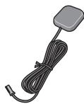
GPS aerial

Metal sheet
When installing the aerial inside the vehicle (on the dashboard or rear shelf)

WARNING
Do not install the GPS aerial over any sensors or vents on the dashboard of the vehicle, as doing so may interfere with the proper functioning of such sensors or vents and may compromise the ability of the metal sheet under the GPS aerial to properly and securely affix to the dashboard.
Affix the metal sheet on as level a surface as possible where the GPS aerial faces the window. Place the GPS aerial on the metal sheet. (The GPS aerial is fastened with its magnet.)
Metal Sheet
Peel off the protective sheet on the rear.
Clamps
Use separately sold clamps
to secure the lead where necessary inside the vehicle.

Notes
- When attaching the metal sheet, do not cut it into small pieces.
- Some models use window glass that does not allow signals from GPS satellites to pass through. On such models, install the GPS aerial on the outside of the vehicle.
Installing the microphone
Install the microphone in a place where its direction and distance from the driver make it easiest to pick up the driver's voice.
- Make sure to connect the microphone to the navigation system after the system is turned off. (ACC OFF)

Parts supplied
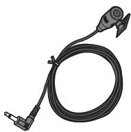
Microphone
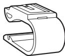

Microphone clip
Double-sided tape
Mounting on the sun visor
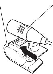
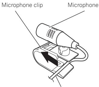
1 Install the microphone in the microphone clip.
Microphone clip
Microphone
2 Attach the microphone clip to sun visor.
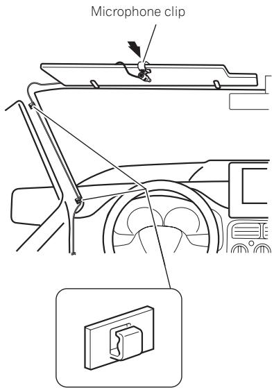
Clamps
Use separately sold clamps to secure the lead where necessary inside the vehicle.
Install the microphone on the sun visor when it is in the up position. It cannot recognise the driver's voice if the sun visor is in the down position.
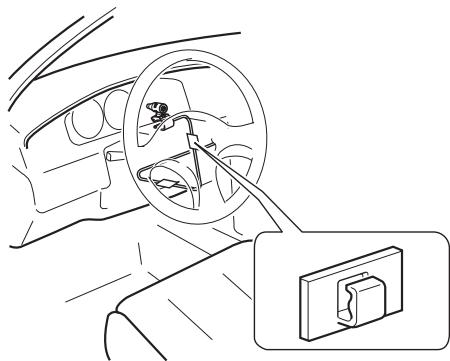
Installation on the steering column
1 Install the microphone in the microphone clip.
Fit the microphone cord in the groove.
2 Mount the microphone clip on the steering column.
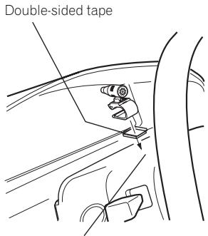
Install the microphone clip on the steering column, keeping it away from the steering wheel.
Clamps
Use separately sold
clamps to secure the
lead where necessary inside the vehicle.
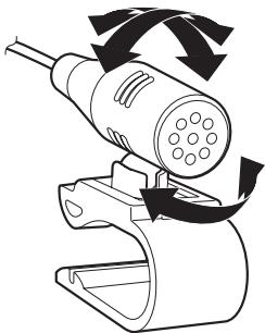
Adjusting the microphone angle
The microphone angle can be adjusted.

After Installing this navigation system
1 Reconnecting the battery.
First, double-check that all connections are correct and that this product is installed correctly. Reassemble all vehicle components that you previously removed. Then reconnect the negative (-) cable to the negative (-) terminal of the battery.
2 Start the engine.
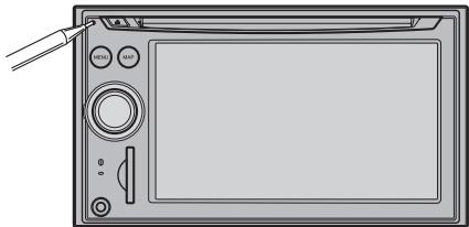
3 Press RESET button.
Press RESET button on the navigation unit using a pointed object such as the tip of a pen.
4 Make the following settings:
For details concerning operations, refer to "Operation Manual".
1 Set the language.
2 Drive an unobstructed road until the GPS starts receiving the signal normally.
3 Make some necessary adjustments.
Setting the time
- Setting the units and the date format, etc.
- Change other settings as you prefer

Note
After installing this navigation system, be sure to check at a safe place that the vehicle is performing normally.
01 INFORMACION IMPORTANTE
ACERCA DE SU NUEVO SISTEMA DE NAVEGACION Y ESTE MANUAL 31
12 PRECAUCIONES IMPORTANTES
| OK | ∅ |
| L V G R | L R G V |
| OK | ∅ |
| L V G R | L R G V |
Ondersteuning (of accession)

Rood (*5)
Accessoire (of ondersteuning)
Geel (^*2)
| OK | ∅ |
| L V G R | L R G V |
L: Linkeraudio (Wit)
R: Rechteraudio (Rood)
V: Video (Geel)
G:A Harding

4-1, MEGURO 1-CHOME, MEGURO-KU
PIONEER ELECTRONICS (USA) INC.
P.O. Box 1540, Long Beach, California 90801-1540, U.S.A.
TEL: (800) 421-1404
PIONEER EUROPE NV
Haven 1087, Keetberglaan 1, B-9120 Melsele, Belgium/Belgique
TEL: (0) 3/570.05.11

- INSTALLATION MANUAL MANUEL D'INSTALLATION
- IMPORTANT SAFEGUARDS
- Connecting the System
- Installation
- After Installation
- ABOUT YOUR NEW NAVIGATION SYSTEM AND THIS MANUAL
- WARNING
- PLEASE READ ALL OF THESE INSTRUCTIONS REGARDING YOUR NAVIGATION SYSTEM AND RETAIN THEM FOR FUTURE REFERENCE
- Precautions before connecting the system
- CAUTION
- Before installing this product
- To prevent damage
- Notice for the blue lead
- Connecting the System
- Notice for the blue/white lead
- Parts supplied
- Connecting the power cord (1)
- Note
- Notes
- Cap (*1)
- Yellow (*2)
- Red (*4)
- Orange/white
- Black (earth)
- Yellow/black
- Speaker leads
- Connecting the power cord (2)
- Pink (CAR SPEED SIGNAL INPUT)
- Light green
- Connection method
- When connecting to separately sold power amp
- When connecting a rear view camera
- When connecting the rear display
- When using a rear display connected to rear video output
- When connecting the external video component Using "AV1 Input" (AV1)
- Using "AV2 Input" (AV2)
- Precautions before installation
- To guard against electromagnetic interference
- Before installing
- Installing this navigation system
- Installation notes
- Before installing this navigation unit
- - Remove the holder.
- Installation with the holder and side bracket
- Install the holder into the dashboard.
- Installation using the screw holes on the side of the navigation unit
- Remove the side brackets.
- Fastening the navigation unit to the factory radio-mounting bracket.
- Installing the GPS aerial
- When installing the aerial inside the vehicle (on the dashboard or rear shelf)
- Installing the microphone
- Mounting on the sun visor
- Install the microphone in the microphone clip.
- Attach the microphone clip to sun visor.
- Installation on the steering column
- Mount the microphone clip on the steering column.
- Adjusting the microphone angle
- After Installing this navigation system
- Reconnecting the battery.
- Start the engine.
- Press RESET button.
- Make the following settings:
- INFORMACION IMPORTANTE
- PRECAUCIONES IMPORTANTES
- Rood (*5)
- Geel (*2)
Brand : PIONEER
Model : AVIC-F910BT
Category : GPS Navigation System