AVH-3200DVD - Multimedia car stereo PIONEER - Free user manual and instructions
Find the device manual for free AVH-3200DVD PIONEER in PDF.
Download the instructions for your Multimedia car stereo in PDF format for free! Find your manual AVH-3200DVD - PIONEER and take your electronic device back in hand. On this page are published all the documents necessary for the use of your device. AVH-3200DVD by PIONEER.
USER MANUAL AVH-3200DVD PIONEER
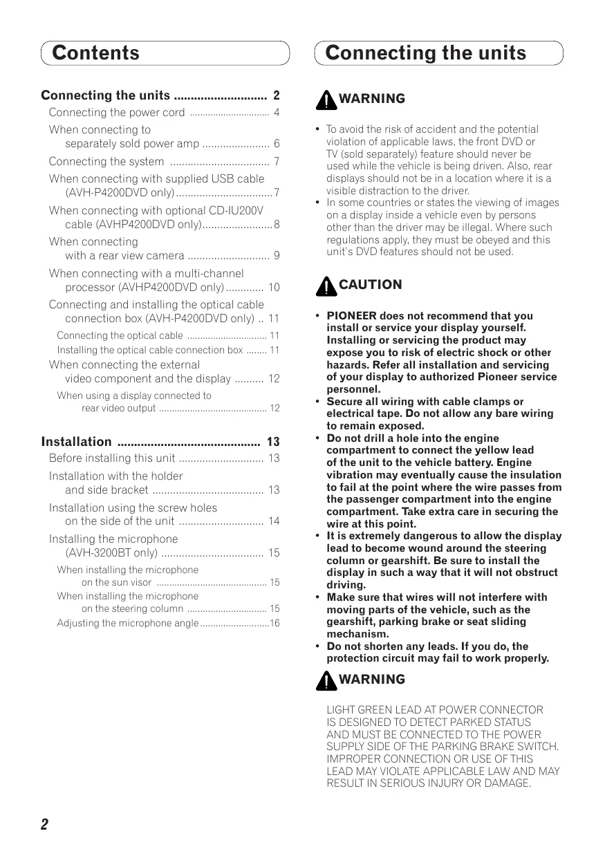
( Contents ) Connecting the units … Connecting the power cord 4 When connecting to separately sold power amp 6 Connecting the system 7 When connecting with supplied USB cable (AVH-P4200DVD only) 7 When connecting with optional CD-IU200V cable (AVHP4200DVD only). 8 When connecting with a rear view camera 9 When connecting with a multi-channel processor (AVHP4200DVD only) 10 Connecting and installing the optical cable connection box (AVH-P4200DVD only) .. 11 Connecting the optical cable 1 Installing the optical cable connection box …… 11 When connecting the external video component and the display 12 When using a display connected to rear video output 12 Installation Before installing this unit 13 Installation with the holder and side bracket 13 Installation using the screw holes on the side of the unit 14 Installing the microphone (AVH-3200BT only) 15 When installing the microphone on the sun visor 15 When installing the microphone on the steering column 15 Adjusting the microphone angle 1ô ( Connecting the units
A varRNING To avoid the risk of accident and the potential violation of applicable laws, the front DVD or TV (sold separately) feature should never be used while the vehicle is being driven. Also, rear displays should not be in a location where it is a visible distraction to the driver. +_In some countries or states the viewing of images on a display inside a vehicle even by persons other than the driver may be illegal. Where such regulations apply, they must be obeyed and this unit's DVD features should not be used À cauTion + PIONEER does not recommend that you or service your display yourself. g or servicing the product may expose you to risk of electric shock or other hazards. Refer all installation and servicing of your display to authorized Pioneer service personnel. Secure all wiring with cable clamps or electrical tape. Do not allow any bare wiring to remain exposed. Do not drill a hole into the engine compartment to connect the yellow lead of the unit to the vehicle battery. Engine vibration may eventually cause the insulation to fail at the point where the wire passes from the passenger compartment into the engine compartment. Take extra care in securing the wire at this point. + His extremely dangerous to allow the display lead to become wound around the steering column or gearshift. Be sure to install the isplay in such a way that it will not obstruct
Make sure that wires will not interfere with moving parts of the vehicle, such as the gearshift, parking brake or seat sliding mechanism. Do not shorten any leads. If you do, the protection circuit may fail to work properly. A varNING
( Connecting the units D € Brmoortant +_ This unit cannot be installed in a vehicle without ACC (accessory) position on the ignition switch ACC position No ACC position Use of this unit in conditions other than the following could result in fire or malfunction. —Vehicles with a 12:volt battery and negative grounding. — Speakers with 50 W (output value) and 4 ohm +0 8 ohm (impedance value) To prevent short-circuit, overheating or malfunction, be sure to follow the directions below —Disconnect the negative terminal of the battery before installation. —Secure the wiring with cable clamps or adhesive tape. Wrap adhesive tape around wéiring that comes into contact with metal parts to protect the wiring. — Place all cables away from moving parts, such as gear shift and seat rails. — Place all cables away from hot places, such as near the heater outlet — Do not connect the yellow cable to the battery by passing it through the hole to the engine compartment. — Cover any disconnected cable connectors with insulating tape. — Do not shorten any cables. — Never cut the insulation of the power cable of this unit in order to share the power with other devices. The current capacity ofthe cable is limited. — Use a fuse ofthe rating prescribed — Never wire the speaker negative cable directly to ground — Never band together negative cables of multiple speakers When this unit is on, control signals are sent through the blueawhite cable. Connect this cable to the system remote control of an external power amp or the vehicle's auto-antenna relay control terminal (max. 300 mA 12 V DC). If the vehicle is equipped with a glass antenna, connect it to the antenna booster power supply terminal. Never connect the blue/white cable to the power terminal of an external power amp. Also, never connect it to the power terminal of the auto antenna. Doing so may result in battery drain or a malfunction IP-BUS connectors are color-coded. Be sure to connect connectors of the same color. The black cable is ground. Ground cables for this unit and other equipment (especially, high- current products such as power amps) must be wired separately. they are not, an accidental detachment may result in a fire or matfunction
(Connecting the units Connecting the power cord Navigation unit (AVIC-F220 (sold separatelÿ))
Please contact your dealer to AUX jack (3.5 @) (AVH-P4200DVD only) Use a mini plug cable to connect with auxiliary device. Microphone input (AVH-3200BT ony) 5 pin cable (Supplied with Navigation unit) Insert d inquire about the connectable navigation unit Not Depending on the kind of vehicle, the function of 2* and 4* may be different. In this case, be sure to connect 1% to 4* and 3* to 2* 6 pin cable in the direction indicated in the figure RGB input —|
Connect leads of the same color to each other <<) EG Yellow (2*) Yellow (1*) Backup or accessorÿ) supply terminal Connect to the constant 12 V
Red (4*) Accessory (or backup) Red (3*) ignition switch Connect ta terminal controlled by (2VDC) Orange/white Connect to lighting switch terminal Black (chassis ground) Connect to
ISO connector Note: In some vehicles, t two. In this case, be O connector may be divided into e to connect to both connectors. {AWH-P4200DVD oniy) When you connect the separately sold multi-channel processor (DEQ-P6600) to this unit, do not connect anything to the speaker leads and system remote control (blue/white). clean, paint-free metal location. ‘Speaker leads White: Frot White/black: Fror Gray Front right ® Gray/ble Front right © Green. Rear left © or subwoofer © Greer/black: Rear left © or subwoofer © Violet Rear right ® or subwoofer ® Violet/black: Rear right © or subwoofer ©
( Connecting the units ) € 4@ roc (AVH-3200BT only) Wired remote input
Hardwired remote control acaptor can be connected (sold separately) Fuse resistor Violetiwhite Ofthe two lead wires connected to the back lamp, connect the one in which the voltage changes when the gear shift is in the REVERSE (R) position. This connection enables the unit to sense whether the car is moving fonwards or backwarcis. Yellow/black If you use an equipment with Mute function, wire this lead to the Audio Mute lead on that equipment. If not, keep the Audio Mute lead free of any connections. Connection method
1. Clamp the lead. 2. Clamp firmly with
needle-nosed pliers. Note: The position ofthe parking brake switch depends on the vehicle model. For details, consult the vehicle Owner's Manual or dealer. Light green Used to detect the ON/OFF status of the parking brake. This lead must be connected to the power supply side of the parking brake switch Blueñwhite Connect to system control terminal of the power amp (max. 300 mA 12 V DC) Parking brake Power supply side switch Ground side Blue/white (6*) Connect to auto-antenna relay control terminal {max. 300 mA 12 V DC) Blue/white (5 The pin position of the ISO)
“uôuz ÿ connector will differ depending on Notes: the type of vehicle. Connect 5* and Change the initial setting of this unit (refer to the Operation Manual). The 6* when Pin 5 is an antenna control subwoofer output of this unit is monaural type. In another type of vehicle, When using a subwoofer of 70 W (2.Q), be sure to connect with Violet and never connect 5* and 6*. Violet/black leads of this unit. Do not connect anything to Green and Green/black leads,
( Connecting the units When connecting to separately sold power amp Rear output Front output io rear output io front autpul Subwoofer output This product |P4200DVD : on !To subwoofer output m control terminal of the power amp {max. 300 mA 12 V DC)
Power amp (sold separately) Power amp (sold separately) Power amp sold separately) Connect with RCA cables Id separatelÿ) Blue/white (54) The pin position of the ISO connector will differ depending on the type of vehicle. Connect 5* and 6* when Pin 5 is an antenna control type. In another type of vehicle, never connect 5* and 6*. {AVH-P4200DVD only) «When you connect the separately sold multi-channel processor (DEQ-P6600) to this unit, do not connect anything to the speaker leads and system remote control (blue/white) «When you connect the mult-channel processor to this unit, refer to multi-channel processor's installation manual for the connection method! Perform these connections whi using the optional amplifier. Blue/white (6*) Connect to auto-antenna relay control terminal {max. 300 mA 12 V DC) Subwoofer ote control Subwoofer Front speaker
( Connecting the units ) € Connecting the system Microphone (AVELP4200DVD/AVE-22008T for hands-free phoning (AVKPA20ODMDYAUHS200BT on) (supplied with Bluetooth adapten PBUS input Bluetooth adapter e.9. CD-BTB200) (sold separately) {AYH-P4200DVD only) This product Wired remote input (AVH-P4200DVD only) Hardwired remote control adaptor can be connected IP.BUS cable (sold separately) (Supplied with Bluetooth adapter) When connecting with supplied USB cable (AVH-P4200DVD only) Microphone for hands-free phoning supplied with Bluetooth adapten Bluetooth adapter (e:9. CD-BTB200) IP-BUS input L (sold separately) Wired remote input Hard-wired remote control adaptor can be connected (sold separateh) pare Black USB ca (supplied with this unit) Conneet te sparate à IPBUS cable Connect Lo sparately sold (Supplied with Bluetooth adapten USB device CORRECTE .
( Connecting the units J'& When connecting with op nal CD-IU200V cable (AVH- P4200DVD only) Microphone for hands-free phoning PUS qu pe supplied with Bluetooth adapter) — 4 AUX input (AUX) Wired remote input Bluetooth adapter Hardwired remote control adaptor e.g. CD-BTB200) can be connected (sold separately) | (sold separately)
iPod with video capabilities {sol separately) 8 input nn Er.
Dock cannector IP-BUS cable (Supplied with Bluetooth adapter)
Interface cable (CD-IU200V) (sold separately)
( Connecting the units ) €
When connecting with a rear view camera When this product is used with a rear view camera, it is possible to automatically switch from the video to rear view image when the gear shift is moved to REVERSE (R). AvArRNING USE INPUT ONLY FOR REVERSE OR MIRROR IMAGE REAR VIEW CAMERA. OTHER USE MAY RESULT IN INJURY OR DAMAGE. À cauTIoN +_ The screen image may appear reversed. +_ The rear view camera function is to be used as an aid for backing into a tight parking spot. Do not use this function for entertainment purposes + Objects in the rear view may appear closer or more distant than they actually are À caurion Rear view camera input (R.C IN) You must use a camera which outputs mirror reversed images. (AVH-P4200DVD/AVH-3200BT only) | To video output SIT 8 Er» (ED —>| Rearviewcamera 0000 0 0 {sold separately) 00000 Ex T R] RCA cable (sold separately) This product l (AŸH-P4200DVD only) Violet/white Ofthe two lead wires connected ta the back lamp, connect the one in which the voltage changes when the gear shift is in the REVERSE (R) position. This connection enables the unit to sense whether the car is moving forwards or backwards. + Itis necessary to set Camera Polarity properly in System when connecting the rer view camera.
( Connecting the units ) € When connecting with a multi-channel processor (AVH- P4200DVD only) Microphone for hands-free phoning {supplied with Bluetooth adapter) … Bluetooth adapter his product (ea. CD-BTB200) (sold separately) IP.BUS input es Wired remote input dwired remote AIT control adaptor can be connected Optic4 (sold separately) To SWR IP-BUS cable . 5 (Supplied with Bluetooth adapter)
Black@ | Optical cable connection box (supplied with multi-channel processor)
RCA cable (supplied with multi-channel processor) Optical cable {supplied with multi-channel processor) annel proces: (DEQ-P6E IP-BUS cable (supplied with
(Connectingthe units
Connecting and installing the optical cable connection box (AVH-P4200DVD only) AvArRNING + Avoid installing the optical cable connection box in locations where the operation of safety devices such as airbags is prevented by this unit. Otherwise, there is a danger of a fatal accident. Avoid installing the optical cable connection box in locations where the operation of the brake may be prevented. Otherwise, it may result in a traffic accident. Fix the optical cable connection box securely with the hook and loop fastener or lock tie. If the unit is loose, it disturbs driving stability, which may result in a traffic accident. À cAUTIoN + Install this unit using oniythe parts supplied with this unit, If other parts are used, this unit may be damaged or could dismount itself, which leads to an accident or other problems Do not install this unit near the doors where rainwater is likely to be spilled on the unit Incursion of water into the unit may cause smoke or fire. Connecting the optical cable
1. Connect the optical cable and ground
lead to the main uni Connect the optical cable so that it does not protrude from the main unit, as shown in the illustration. Fasten the ground lead to the protrusion on the back of the main unit. o o -Screw
2. Connect the optical cable to the
optical cable connection box. optical cable Installing the optical cable connection box + When installing the optical cable connection box with the hook and loop fastener. Install the opt cable connection box using the haok and loop fastener in the ample space of the console box. us S) fastener x fastener
+ Wheninstalling the optical cable connection box with the lock tie. Wrap the optical cable and connection box
with the protection tape and fasten with the power code using the lock tie. Wrap with the protection tape Fasten with the lock tie
[f CE To video output o [mb L_ \ To audio outputs This product Audio input (AVH-P4200DVD only) (LIN, RIN) External video component (sold separatelÿ) + Itis necessary to change AV Input in System when connecting the external video component When using a display connected to rear video output This products rear video output and rear audio output are for connection of a display to enable passengers in the rear seats to watch the DVD, etc. Avarninc Never install the display in a location where it is le to the driver while driving.
HA Note Check all connections and systems before final installation. Do not use unauthorized parts as this may cause malfunctions. Consult your dealer if installation requires drilling of holes or other modifications to the vehicle Do not install this unit where: — it may interfere with operation of the vehicle — it may cause injury to a passenger as a result of a sudden stop. Do not install the display where it may (i) obstruct the drivers vision, (i) impair the performance of any of the vehicle's operating systems or safety features, including air bags, hazard lamp buttons or ii) impair the drivers ability to sately operate the vehicle The semiconductor laser will be damaged if it overheats. Install this unit away from hot places such as near the heater outlet. Optimum performance is obtained when the unit is installed at an angle of less than 30°. 30° When installing, to ensure proper heat dispersal when using this unit, make sure you leave ample space behind the rear panel and wrap any loose cables so they are not blocking the vents Leave ample space Dashboard oem focm Installation )
- Remove the holder. Loosen the screws (3 X 6 mm) to remove the holder. ys! sug Rs. Holder {Supplied with this unit) DNS noi
Screw (3 x 6 mm) —3% (Supplied with this unit) Installation with the holder and side bracket
1. Install the holder into the dashboard.
After inserting the holder into the dashboard, select and bend the tabs appropriate to the thickness of the dashboard material. (Install this unit as firmly as possible using the top and bottom tabs. To secure this unit, bend the tabs 90 degrees.) Dashboard Holder(Supplied with this unit)
2. Install this unit and fasten the screws.
Rubber bush ASupplied with this unit) Double-ended screw (Supplied with this unit)
Screw (8 x 6 mm) = (Supplied with this unit)
3. Attach the trim ring.
Tim ring 7 (Supplied with this unit) Installation using the screw holes on the side of the unit
1. Remove the side brackets.
Side bracket (Supplied with this unit) Qu Screw for fixing the side bracket (5 x 9 mm) (Supplied with this unit) Tapping screw (6 mm x 8 mm)
2. Fastening the unit to the factory
radio-mounting bracket. Position the unit so that its screw holes are aligned with the screw holes of the bracket
and tighten the screws at 3 or 4 locations on each side. Factory radio mounting bracket ÉANote Ithe pawl gets in the way, bend it down: Dashboard or console In some types of vehicles, discrepancy may oceur between the unit and the dashboard. If this happens, use the supplied frame to fill the gap.
(Installation ) Installing the microphone (AVH-3200BT only) Installation notes Install the microphone in a position and orientation that will enable it to pick up the voice of the person operating the system À cauTIoN +_Itis extremely dangerous to allow the microphone lead to become wound around the steering column or gearstick. Be sure to install the unit in such a way that it will not obstruct driving. When installing the microphone on the sun visor
visor. + With the sun visor up, install the microphone clip. (Lowering the sun visor reduces the voice recagnition rate.)
Microphone clip Clamp Use separately sold clamps to secure the lead where necessary inside the vehicle When installing the microphone on the steering column
1. Install the microphone on the
microphone clip. Microphone base Fit the microphone lead into the groove. + Microphone can be installed without using microphone clip. In this case, detach the microphone base from the microphone clip. To detach the microphone base from microphone clip, slide the microphone base
2. Install the microphone clip on the
steering column. Double-sided tape Install the microphone clip on the rear side of the steering column Clamp Use separately sold | clamps to secure the lead where necessary inside the vehicle. Adjusting the microphone angle The microphone angle can be adjusted