USER MANUAL AVH-P4100DVD PIONEER
Connecting the units 3
Parts supplied 5
Connecting the power cord 6
When connecting to separately sold power amp 8
When connecting
with supplied USB cable .... 9
When connecting
with optional CD-IU200V cable ..... 9
When connecting
with a rear view camera .... 10
When connecting with a multi-channel processor ..... 11
Connecting and installing
the optical cable connection box .... 12
Connecting the optical cable 12
Installing the optical cable connection box ..... 12
When connecting the external video component and the display ..... 13
When using a display connected to rear video output 13
Installation 14
Before installing this unit 14
Installation with the holder and side bracket 14
Installation using the screw holes on the side of the unit 15
Connecting the units

WARNING
- To avoid the risk of accident and the potential violation of applicable laws, the front DVD or TV (sold separately) feature should never be used while the vehicle is being driven. Also, rear displays should not be in a location where it is a visible distraction to the driver.
- In some countries or states the viewing of images on a display inside a vehicle even by persons other than the driver may be illegal. Where such regulations apply, they must be obeyed and this unit's DVD features should not be used.

CAUTION
- PIONEER does not recommend that you install or service your display yourself. Installing or servicing the product may expose you to risk of electric shock or other hazards. Refer all installation and servicing of your display to authorized Pioneer service personnel.
- Secure all wiring with cable clamps or electrical tape. Do not allow any bare wiring to remain exposed.
- Do not drill a hole into the engine compartment to connect the yellow lead of the unit to the vehicle battery. Engine vibration may eventually cause the insulation to fail at the point where the wire passes from the passenger compartment into the engine compartment. Take extra care in securing the wire at this point.
- It is extremely dangerous to allow the display lead to become wound around the steering column or gearshift. Be sure to install the display in such a way that it will not obstruct driving.
- Make sure that wires will not interfere with moving parts of the vehicle, such as the gearshift, parking brake or seat sliding mechanism.
- Do not shorten any leads. If you do, the protection circuit may fail to work properly.

WARNING
LIGHT GREEN LEAD AT POWER CONNECTOR IS DESIGNED TO DETECT PARKED STATUS AND MUST BE CONNECTED TO THE POWER SUPPLY SIDE OF THE PARKING BRAKE SWITCH. IMPROPER CONNECTION OR USE OF THIS LEAD MAY VIOLATE APPLICABLE LAW AND MAY RESULT IN SERIOUS INJURY OR DAMAGE.
Connecting the units

Note
- This unit cannot be installed in a vehicle without ACC (accessory) position on the ignition switch.

ACC position

No ACC position
- Use this unit in other than the following conditions could result in fire or malfunction.
—Vehicles with a 12-volt battery and negative grounding.
—Speakers with 50 W (output value) and 4 ohm to 8 ohm (impedance value).
- To prevent short-circuit, overheating or malfunction, be sure to follow the directions below.
—Disconnect the negative terminal of the battery before installation.
— Secure the wiring with cable clamps or adhesive tape. To protect the wiring, wrap adhesive tape around them where they lie against metal parts.
—Place all cables away from moving parts, such as gear shift and seat rails.
—Place all cables away from hot places, such as near the heater outlet.
—Do not pass the yellow cable through a hole into the engine compartment to connect to a battery.
—Cover any disconnected cable connectors with insulating tape.
—Do not shorten any cables.
— Never cut the insulation of the power cable of this unit in order to share the power to other equipment. Current capacity of the cable is limited.
—Use a fuse of the rating prescribed.
—Never wire the speaker negative cable directly to ground.
—Never band together multiple speaker's negative cables.
- Control signal is output through blue/white cable when this unit is powered on. Connect it to an external power amp's system remote control or the vehicle's auto-antenna relay control terminal (max. 300 mA, 12 V DC). If the vehicle is equipped with a glass antenna, connect it to the antenna booster power supply terminal.
- Never connect blue/white cable to external power amp's power terminal. Also, never connect it to the power terminal of the auto antenna. Otherwise, battery drain or malfunction may result.
- IP-BUS connectors are color-coded. Be sure to connect connectors of the same color.
- Black cable is ground. This cable and other product's ground cable (especially, high-current products such as power amp) must be wired separately. Otherwise, fire or malfunction may result if they are accidentally detached.
Connecting the units
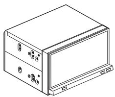
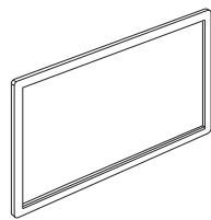
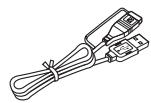
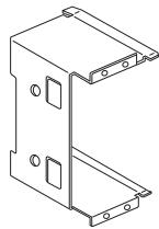
Parts supplied
Parts marked (*) are pre-installed.
natural_image
Line drawing of a rectangular electronic device with mounting holes and a front panel (no text or symbols)
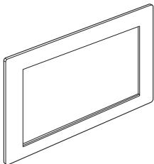
This product

natural_image
Pure electrical circuit lines without any symbols
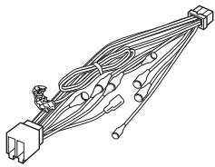
Power cord

USB cable

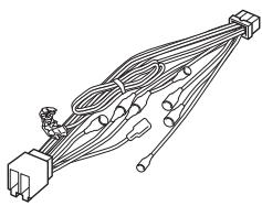
natural_image
Isometric line drawing of a rectangular electronic enclosure with mounting holes and internal slots (no text or symbols)
Holder*

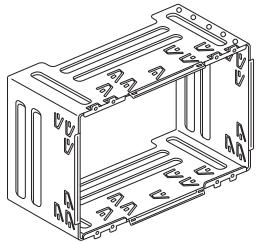
natural_image
Technical line drawing of a mechanical bracket or mounting plate (no text or symbols)
Side bracket (2 pcs.)*

natural_image
Simple line drawing of a rectangular frame with no text or symbols
Trim ring

natural_image
Simple line drawing of a rectangular frame with no text or symbols
Frame


Flush surface screw
(5 mm × 8 mm) (8 pcs.)
(4 pcs. are pre-installed.)
Binding screw
(5 mm × 8 mm) (8 pcs.)

Binding screw*
(3 mm × 6 mm) (8 pcs.)

Rubber bush
Double-ended screw
Touch panel pen
Connecting the units
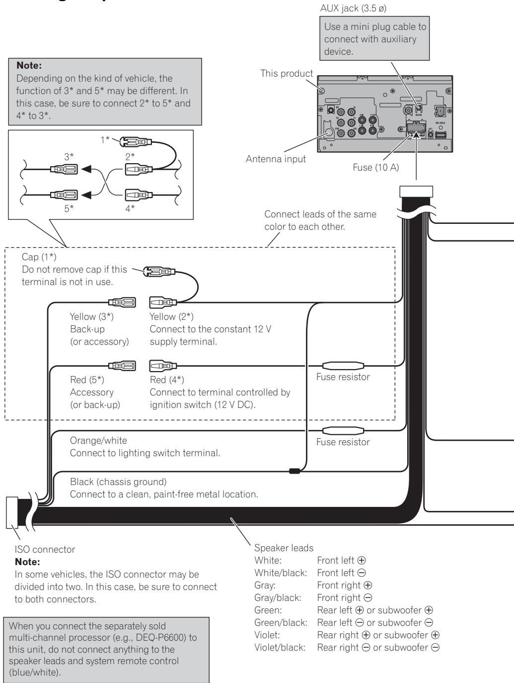
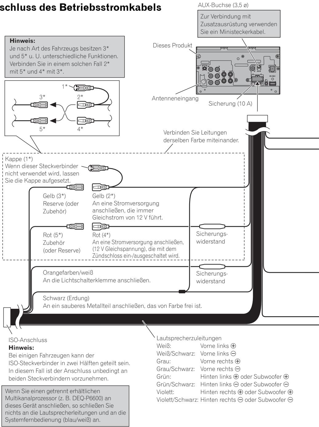
Connecting the power cord
flowchart
graph TD
    A["ISO connector"] --> B["Cap (1*) Do not remove cap if this terminal is not in use."]
    B --> C["Yellow (3*) Back-up (or accessory)"]
    B --> D["Yellow (2*) Connect to the constant 12 V supply terminal."]
    B --> E["Red (5*) Accessory (or back-up)"]
    B --> F["Red (4*) Connect to terminal controlled by ignition switch (12 V DC)."]
    B --> G["Orange/white Connect to lighting switch terminal."]
    B --> H["Black (chassis ground) Connect to a clean, paint-free metal location."]
    A --> I["AUX jack (3.5ø) Use a mini plug cable to connect with auxiliary device."]
    I --> J["This product"]
    J --> K["Fuse (10 A)"]
    K --> L["Fuse resistor"]
    L --> M["Fuse resistor"]
    M --> N["Speaker leads White: Front left ⊕ White/black: Front left ⊖ Gray: Front right ⊕ Gray/black: Front right ⊖ Green: Rear left ⊕ or subwoofer ⊕ Green/black: Rear left ⊖ or subwoofer ⊖ Violet: Rear right ⊕ or subwoofer ⊕ Violet/black: Rear right ⊖ or subwoofer ⊖"]
    style A fill:#f9f,stroke:#333
    style B fill:#ccf,stroke:#333
    style C fill:#cfc,stroke:#333
    style D fill:#cfc,stroke:#333
    style E fill:#cfc,stroke:#333
    style F fill:#cfc,stroke:#333
    style G fill:#cfc,stroke:#333
    style H fill:#cfc,stroke:#333
    style I fill:#fcc,stroke:#333
    style J fill:#ffc,stroke:#333
    style K fill:#ffc,stroke:#333
    style L fill:#ffc,stroke:#333
    style M fill:#ffc,stroke:#333
    style N fill:#ffc,stroke:#333
    style O fill:#ffc,stroke:#333
    style P fill:#ffc,stroke:#333
    style Q fill:#ffc,stroke:#333
    style R fill:#ffc,stroke:#333
    style S fill:#ffc,stroke:#333
    style T fill:#ffc,stroke:#333
    style U fill:#ffc,stroke:#333
    style V fill:#ffc,stroke:#333
    style W fill:#ffc,stroke:#333
    style X fill:#ffc,stroke:#333
    style Y fill:#ffc,stroke:#333
    style Z fill:#ffc,stroke:#333
    style AA fill:#ffc,stroke:#333
    style AB fill:#ffc,stroke:#333
    style AC fill:#ffc,stroke:#333
    style AD fill:#ffc,stroke:#333
    style AE fill:#ffc,stroke:#333
    style AF fill:#ffc,stroke:#333
    style AG fill:#ffc,stroke:#333
    style AH fill:#ffc,stroke:#333
    style AI fill:#ffc,stroke:#333
Fuse resistor
Violet/white
Of the two lead wires connected to the back lamp, connect the one in which the voltage changes when the gear shift is in the REVERSE (R) position. This connection enables the unit to sense whether the car is moving forwards or backwards.
Yellow/black
If you use equipment with Mute function, wire this lead to the Audio Mute lead on that piece of equipment. If not, keep the Audio Mute lead free of any connections.
Connection method
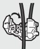
- Clamp the lead.

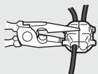
- Clamp firmly with needle-nosed pliers.
Note:
- The position of the parking brake switch depends on the vehicle model. For details, consult the vehicle Owner's Manual or dealer.
Light green
Used to detect the ON/OFF status of the parking brake. This lead must be connected to the power supply side of the parking brake switch.
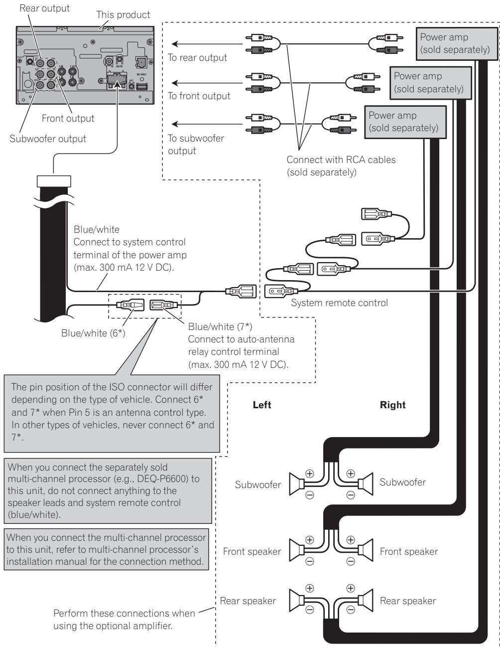
Blue/white
Connect to system control terminal of the power amp (max. 300 mA 12 V DC).
Blue/white (6*)
The pin position of the ISO connector will differ depending on the type of vehicle. Connect 6* and 7* when Pin 5 is an antenna control type. In other types of vehicles, never connect 6* and 7*.
Power supply side
Ground side
Blue/white (7*)
Connect to auto-antenna relay control terminal (max. 300 mA 12 V DC).
Notes:
- Change the initial setting of this unit (refer to the Operation Manual). The subwoofer output of this unit is monaural.
- When using a subwoofer of 70 W (2 Ω), be sure to connect with Violet and Violet/black leads of this unit. Do not connect anything to Green and Green/black leads.
When connecting to separately sold power amp
flowchart
graph TD
    A["Subwoofer output"] --> B["Front output"]
    B --> C["Top output"]
    C --> D["Blue/white (6*)"]
    D --> E["Blue/white Connect to system control terminal of the power amp (max. 300 mA 12 V DC)."]
    E --> F["Power amp (sold separately)"]
    F --> G["Power amp (sold separately)"]
    G --> H["Power amp (sold separately)"]
    H --> I["System remote control"]
    I --> J["Left"]
    I --> K["Right"]
    L["Power amplifier"] --> M["Power amplifier"]
    N["Power amplifier with RCA cables"] --> O["Power amplifier with RCA cables"]
    P["Blue/white connector"] --> Q["Blue/white (7*) Connect to auto-antenna relay control terminal (max. 300 mA 12 V DC)."]
    Q --> R["Blue/white (6*)"]
    S["Blue/white connector"] --> T["Blue/white (7*) Connect to auto-antenna relay control terminal (max. 300 mA 12 V DC)."]
    T --> U["Blue/white (6*)"]
    V["Power input"] --> W["Power input"]
    X["Power output"] --> Y["Power output"]
    Z["Power output"] --> AA["Power output"]
    AB["Power output"] --> AC["Power output"]
    AD["Power output"] --> AE["Power output"]
    AF["Power output"] --> AG["Power output"]
    AH["Power output"] --> AI["Power output"]
    AJ["Power output"] --> AK["Power output"]
    AL["Power output"] --> AM["Power output"]
    AN["Power output"] --> AO["Power output"]
    AP["Power output"] --> AQ["Power output"]
    AR["Power output"] --> AS["Power output"]
    AT["Power output"] --> AU["Power output"]
    AV["Power output"] --> AW["Power output"]
    AX["Power output"] --> AY["Power output"]
    AZ["Power output"] --> BA["Power output"]
    BB["Power output"] --> BC["Power output"]
    BD["Power output"] --> BE["Power output"]
    BF["Power output"] --> BG["Power output"]
    BH["Power output"] --> BI["Power output"]
    BJ["Power output"] --> BK["Power output"]
    BL["Power output"] --> BM["Power output"]
    BN["Power output"] --> BO["Power output"]
    BP["Power output"] --> BQ["Power output"]
    BR["Power output"] --> BS["Power output"]
    BT["Power output"] --> BU["Power output"]
    BV["Power output"] --> BW["Power output"]
    BX["Power output"] --> BY["Power output"]
    BZ["Power output"] --> CA["Power output"]
    CB["Power output"] --> CC["Power output"]
    DD["Power output"] --> DE["Power output"]
    DF["Power output"] --> DG["Power output"]
    DH["Power output"] --> DI["Power output"]
    DJ["Power output"] --> DK["Power output"]
    DL["Power output"] --> DM["Power output"]
    DN["Power output"] --> DO
    DB["Power output"] --> DC
    DBD --> DV
    DX["Derivative Device"] --> DXA["Subwoofer"]
    DXB["Derivative Device"] --> DXC["Subwoofer"]
    DXF["Derivative Device"] --> DXG["Derivative Device"]
    DXH["Derivative Device"] --> DXI["Derivative Device"]
    DXJ["Derivative Device"] --> DXK["Derivative Device"]
    DXL["Derivative Device"] --> DXM["Derivative Device"]
    DXN["Derivative Device"] --> DXO["Derivative Device"]
    DXP["Derivative Device"] --> DXQ["Derivative Device"]
    DXR["Derivative Device"] --> DXS["Derivative Device"]
    DXT["Derivative Device"] --> DXU["Derivative Device"]
    DXV["Derivative Device"] --> DXW["Derivative Device"]
    DXX["Derivative Device"] --> DXX["Derivative Device"]
    DXY["Derivative Device"] --> DXZ["Derivative Device"]
    DXZ["Derivative Device"] --> DXZD["Derivative Device"]
Connecting the units
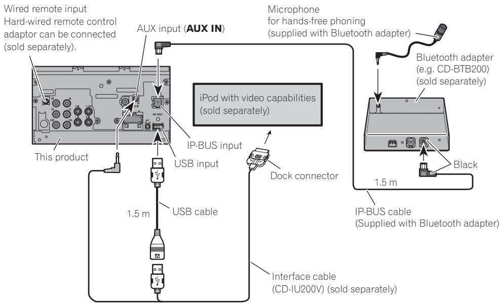
When connecting with supplied USB cable
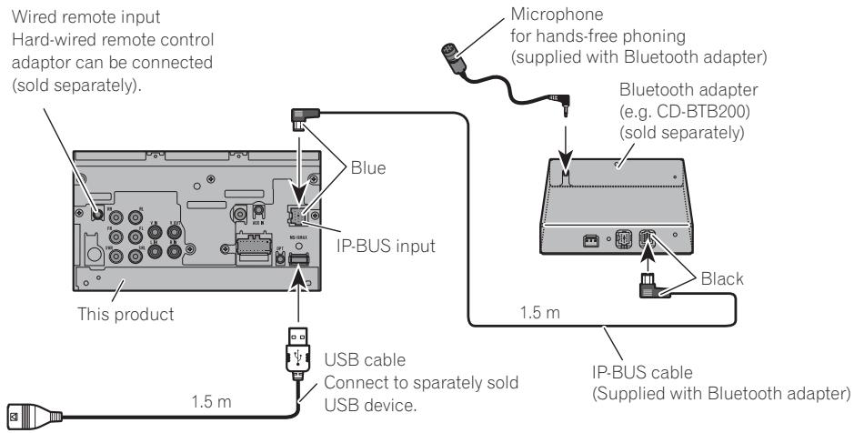
When connecting with optional CD-IU200V cable
Connecting the units
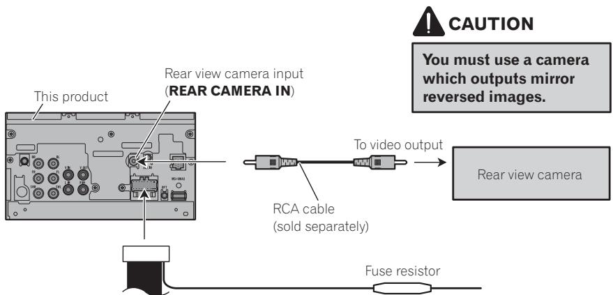
When connecting with a rear view camera
When this product is used with a rear view camera, it is possible to automatically switch from the video to rear view image when the gear shift is moved to REVERSE (R).

WARNING
USE INPUT ONLY FOR REVERSE OR MIRROR IMAGE REAR VIEW CAMERA. OTHER USE MAY RESULT IN INJURY OR DAMAGE.

CAUTION
- The screen image may appear reversed.
- The rear view camera function is to be used as an aid for backing into a tight parking spot. Do not use this function for entertainment purposes.
- Objects in the rear view may appear closer or more distant than they actually are.
Violet/white
Of the two lead wires connected to the back lamp, connect the one in which the voltage changes when the gear shift is in the REVERSE (R) position. This connection enables the unit to sense whether the car is moving forwards or backwards.
- It is necessary to set Camera Polarity properly in System Menu when connecting the rear view camera.
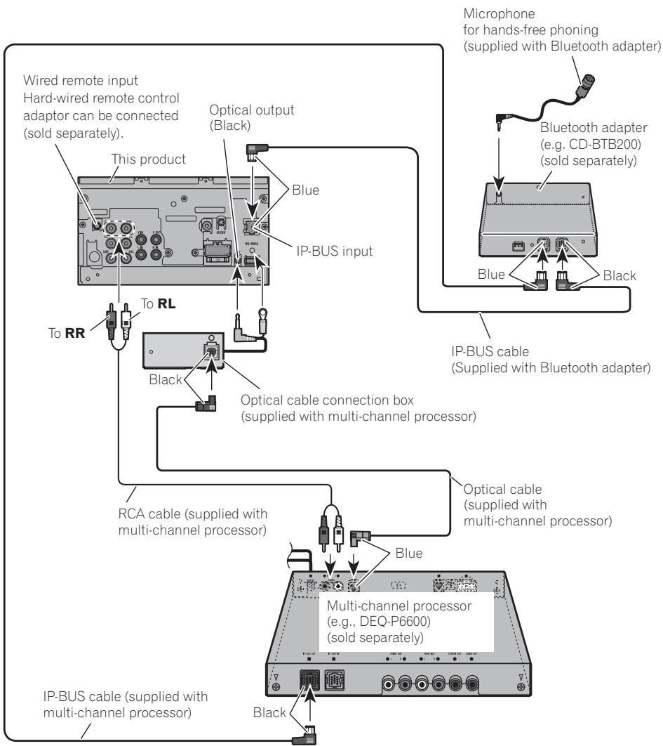
When connecting with a multi-channel processor
Connecting and installing the optical cable connection box

WARNING
- Avoid installing the optical cable connection box in locations where the operation of safety devices such as airbags is prevented by this unit. Otherwise, there is a danger of a fatal accident.
- Avoid installing the optical cable connection box in locations where the operation of the brake may be prevented. Otherwise, it may result in a traffic accident.
- Fix the optical cable connection box securely with the hook and loop fastener or lock tie. If the unit is loose, it disturbs driving stability, which may result in a traffic accident.

CAUTION
- Install this unit using only the parts supplied with this unit. If other parts are used, this unit may be damaged or could dismount itself, which leads to an accident or other problems.
- Do not install this unit near the doors where rainwater is likely to be spilled on the unit. Incursion of water into the unit may cause smoke or fire.
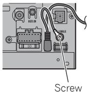
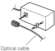
Connecting the optical cable
1. Connect the optical cable and ground lead to the main unit.
Connect the optical cable so that it does not protrude from the main unit, as shown in the illustration. Fasten the ground lead to the protrusion on the back of the main unit.
2. Connect the optical cable to the optical cable connection box.
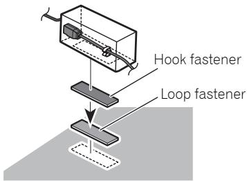
Installing the optical cable connection box
- When installing the optical cable connection box with the hook and loop fastener.
Install the optical cable connection box using the hook and loop fastener in the ample space of the console box.
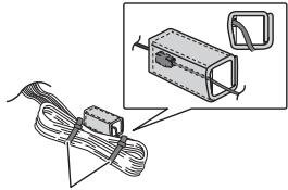
- When installing the optical cable connection box with the lock tie.
Wrap the optical cable and connection box with the protection tape and fasten with the power code using the lock tie.
Wrap with the protection tape
natural_image
Illustration of a cable being wrapped in a box, with an inset showing the same component (no text or symbols present)
Fasten with the lock tie
When connecting the external video component and the display
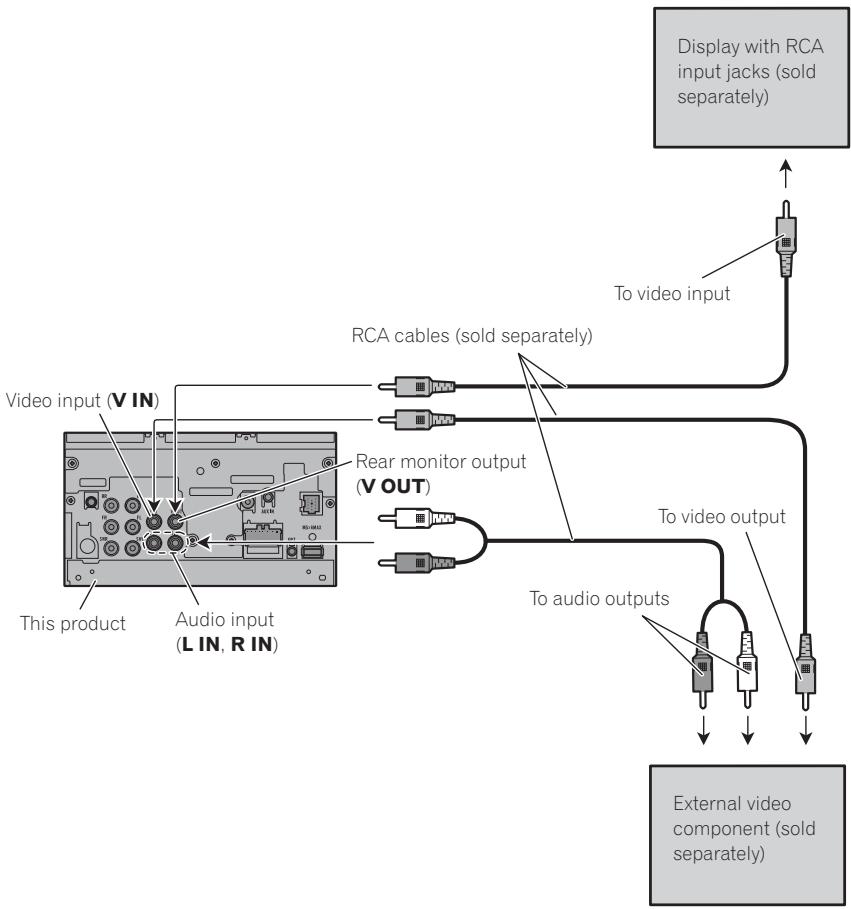
flowchart
graph TD
    A["Display with RCA input jacks (sold separately)"] --> B["To video input"]
    B --> C["RCA cables (sold separately)"]
    C --> D["This product"]
    C --> E["Rear monitor output (V OUT)"]
    E --> F["Audio input (L IN, R IN)"]
    F --> G["External video component (sold separately)"]
    G --> H["To audio outputs"]
    H --> I["To video output"]
- It is necessary to change AV Input in System Menu when connecting the external video component.
When using a display connected to rear video output
This product's rear video output is for connection of a display to enable passengers in the rear seats to watch video.

WARNING
Never install the display in a location where it is visible to the driver while driving.
Installation

Note
- Check all connections and systems before final installation.
- Do not use unauthorized parts. The use of unauthorized parts may cause malfunctions.
- Consult with your dealer if installation requires drilling of holes or other modifications of the vehicle.
- Do not install this unit where:
— it may interfere with operation of the vehicle.
— it may cause injury to a passenger as a result of a sudden stop.
- Do not install the display where it may (i) obstruct the driver's vision, (ii) impair the performance of any of the vehicle's operating systems or safety features, including air bags, hazard lamp buttons or (iii) impair the driver's ability to safely operate the vehicle.
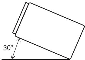
- The semiconductor laser will be damaged if it overheats. Install this unit away from hot places such as near the heater outlet.
- Optimum performance is obtained when the unit is installed at an angle of less than 30^ .
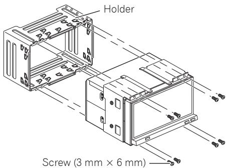
Before installing this unit
- Remove the holder.
Loosen the screws (3 mm × 6 mm) to remove the holder.
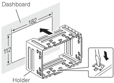
Installation with the holder and side bracket
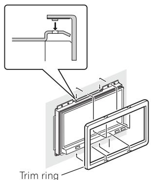
1. Install the holder into the dashboard.
After inserting the holder into the dashboard, select and bend the tabs appropriate to the thickness of the dashboard material. (Install this unit as firmly as possible using the top and bottom tabs. To secure this unit, bend the tabs 90 degrees.)
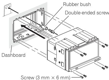
2. Install this unit and fasten the screws.
Installation
3. Attach the trim ring.
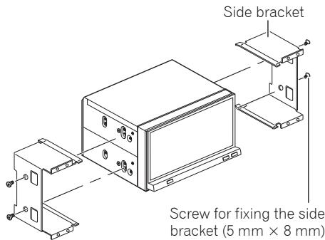
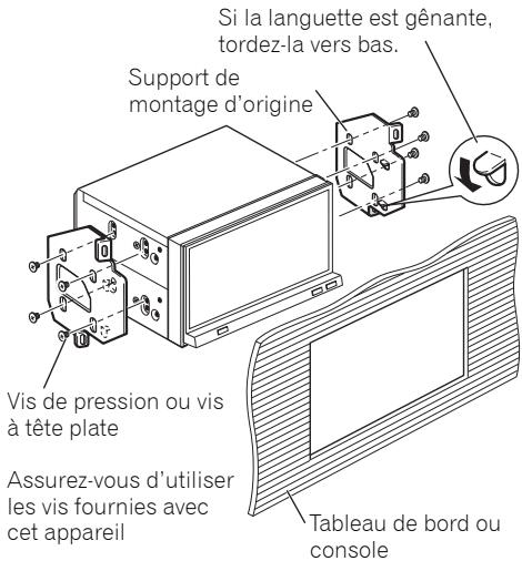
Installation using the screw holes on the side of the unit
1. Remove the side brackets.
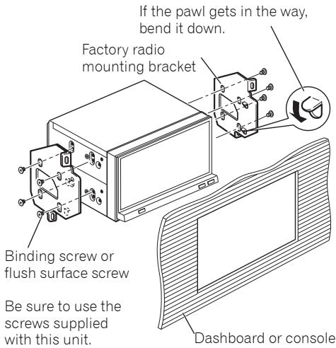
2. Fastening the unit to the factory radio-mounting bracket.
Position the unit so that its screw holes are aligned with the screw holes of the bracket, and tighten the screws at 3 or 4 locations on each side.
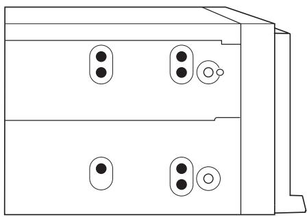
natural_image
Diagram of a dual-chamber electronic device with four ports and circular indicators (no text or symbols)

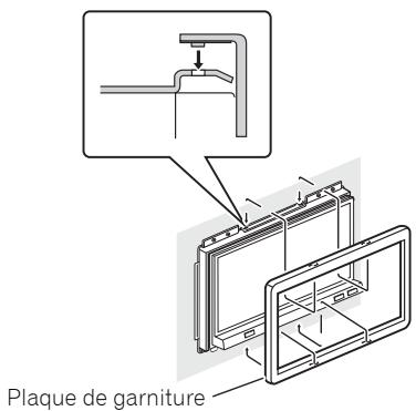
Note
In some types of vehicles, discrepancy may occur between the unit and the dashboard. If this happens, use the supplied frame to fill the gap.
Contenido
Posición ACC

Sin posición ACC
natural_image
Line drawing of a rectangular electronic device with mounting holes and a front panel (no text or symbols)
Este producto

natural_image
Pure electrical circuit lines without any symbols
natural_image
Isometric line drawing of a rectangular electronic enclosure with mounting holes and internal slots (no text or symbols)
Sujetador*

natural_image
Technical line drawing of a mechanical bracket or mounting plate (no text or symbols)
Ménsula lateral (2 piezas)*
natural_image
Simple line drawing of a rectangular frame with no text or symbols
natural_image
Simple line drawing of a rectangular frame with no text or symbols
Bastidor
natural_image
Illustration of a cable connector with a magnified inset showing the internal components (no text or symbols)
natural_image
Diagram of a dual-chamber computer with four ports and circular indicators (no text or symbols)
ACC-Position
Keine ACC-Position
natural_image
Line drawing of a rectangular electronic device with mounting holes and a front panel (no text or symbols)
Dieses Produkt
natural_image
Pure electrical circuit lines without any symbols
Netzkabel

USB-Kabel
natural_image
Isometric line drawing of a rectangular electronic enclosure with mounting holes and internal slots (no text or symbols)
Halterung*

natural_image
Technical line drawing of a mechanical bracket or mounting plate (no text or symbols)
natural_image
Simple line drawing of a rectangular frame with no text or symbols
Trimmring
natural_image
Simple line drawing of a rectangular frame with no text or symbols
Rahmen


Senkschraube
(5 mm × 8 mm) (8 St.)

Klemmschraube ^* (3 mm × 6 mm) (8 St.)

Gummibuchse
Doppelschraube
Touchpanel-Stift
natural_image
Technical line drawing of a mechanical clamp or bracket assembly (no text or symbols)
Hinweise:
natural_image
Diagram of a device with cable and connector, no text or symbols present
Lichtleiterkabel
natural_image
Illustration of a cable connector with a magnified inset showing the internal components (no text or symbols)
natural_image
Diagram of a dual-chamber computer with four ports and indicator lights (no text or labels)
Position ACC
Pas de Position ACC
natural_image
Line drawing of a rectangular electronic device with mounting holes and a front panel (no text or symbols)
Ce produit

natural_image
Pure electrical circuit lines without any symbols
natural_image
Isometric line drawing of a rectangular electronic enclosure with mounting holes and internal slots (no text or symbols)
Support principal*

natural_image
Technical line drawing of a mechanical bracket or mounting plate (no text or symbols)
natural_image
Simple line drawing of a rectangular frame with no text or symbols
Plaque de garniture

natural_image
Simple line drawing of a rectangular frame with no text or symbols
Cadre


Vis de pression*
(3 mm × 6 mm) (8 pcs)
natural_image
Technical line drawing of a mechanical assembly with a lever and base component (no text or symbols)
Remarques:
natural_image
Diagram of a device with cable and connector, no text or symbols present
natural_image
Diagram showing a cable being inserted into a device with a magnified inset (no text or symbols)
• Retirez le support principal.
3. Attachez la plaque de garniture.
natural_image
Diagram of a dual-chamber electronic device with four ports and circular indicators (no text or symbols)
Posizione ACC

natural_image
Line drawing of a rectangular electronic device with two ports and a front panel (no text or symbols)
Questo apparecchio
natural_image
Pure electrical circuit lines without any symbols
natural_image
Isometric line drawing of a rectangular electronic enclosure with mounting holes and internal slots (no text or symbols)
Supporto*

natural_image
Technical line drawing of a mechanical bracket or mounting plate (no text or symbols)
natural_image
Simple line drawing of a rectangular frame with no text or symbols
Bordo di rifinitura

natural_image
Simple line drawing of a rectangular frame with no text or symbols
Cornice


natural_image
Illustration of a cable connector being inserted into a housing (no text or symbols present)
Fissare con fascette
natural_image
Diagram of a dual-chamber electronic device with four ports and circular connectors (no text or symbols)
ACC stand

Geen ACC stand
natural_image
Line drawing of a rectangular electronic device with mounting holes and a front panel (no text or symbols)
Dit product

natural_image
Pure electrical circuit lines without any symbols
Stroomsnoer
USB kabel

natural_image
Isometric line drawing of a rectangular electronic enclosure with mounting holes and internal slots (no text or symbols)
Houder *
natural_image
Technical line drawing of a mechanical bracket or mounting plate (no text or symbols)
natural_image
Simple line drawing of a rectangular frame with no text or symbols
Afwerkingsrand

natural_image
Simple line drawing of a rectangular frame with no text or symbols
Frame


natural_image
Illustration of a cable connector with a magnified inset showing the internal components (no text or symbols)
natural_image
Diagram of a dual-chamber electronic device with four ports and circular buttons (no text or symbols)
4-1, MEGURO 1-CHOME, MEGURO-KU
PIONEER ELECTRONICS (USA) INC.
P.O. Box 1540, Long Beach, California 90801-1540, U.S.A.
TEL: (800) 421-1404
PIONEER EUROPE NV
Haven 1087, Keetberglaan 1, B-9120 Melsele, Belgium
TEL: (0) 3/570.05.11
PIONEER ELECTRONICS ASIACENTRE PTE. LTD.
253 Alexandra Road, #04-01, Singapore 159936
TEL: 65-6472-7555
PIONEER ELECTRONICS AUSTRALIA PTY. LTD.
178-184 Boundary Road, Braeside, Victoria 3195, Australia
TEL: (03) 9586-6300
PIONEER ELECTRONICS OF CANADA, INC.
300 Allstate Parkway, Markham, Ontario L3R 0P2, Canada
TEL: 1-877-283-5901
TEL: 905-479-4411
PIONEER ELECTRONICS DE MEXICO, S.A. de C.V.
Blvd.Manuel Avila Camacho 138 10 piso
Col.Lomas de Chapultepec, Mexico, D.F. 11000
TEL: 55-9178-4270
先鋒股份有限公司
總公司:台北市中山北路二段44號13樓
電話:(02) 2521-3588
先鋒電子(香港)有限公司
香港九龍尖沙咀海港城世界商業中心
9樓901-6室
電話:(0852) 2848-6488
Published by Pioneer Corporation.
Copyright © 2008-2009 by Pioneer Corporation.
All rights reserved.