AVIC-HD3 - GPS Navigation System PIONEER - Free user manual and instructions
Find the device manual for free AVIC-HD3 PIONEER in PDF.
| Product Type | GPS Car Navigation System |
| Brand | PIONEER |
| Model | AVIC-HD3 |
| Power Supply | 12 V DC (vehicle battery, negative pole to ground) |
| Protection Fuse | 10 A |
| Navigation Functions | Voice guidance, route calculation, map display |
| Audio Functions | AM/FM Radio (via optional tuner), auxiliary input, speaker output |
| Video Functions | Video input for rear-view camera, video output for rear monitor |
| Connectivity | IP-BUS (iPod, CD changer), AV-BUS (TV tuner), Bluetooth (via ND-BT1 module) |
| GPS Antenna | Magnetic, 5 m cable, indoor/outdoor mounting |
| Microphone | Included, mounting on sun visor or steering column |
| RCA Audio Outputs | Front, rear, subwoofer (3 outputs) |
| Speed Signal Input | Yes (pink wire) |
| Reverse Light Input | Yes (violet/white wire) |
| Parking Brake Input | Yes (light green wire) |
| Amplifier Remote Control | Blue/white wire (max. 300 mA 12 V DC) |
| Chassis Format | 1-DIN (standard) |
| Supplied Accessories | Power cord, connection cables, mounting bracket, screws, GPS antenna, microphone, waterproof cushion, wire ties |
| Safety | Installation by a certified professional only, do not use while driving (except navigation) |
| Maintenance | Clean with a soft dry cloth; do not use chemical products |
| Repairability | Refer to an authorized Pioneer service; do not attempt repair yourself |
Frequently Asked Questions - AVIC-HD3 PIONEER
User questions about AVIC-HD3 PIONEER
0 question about this device. Answer the ones you know or ask your own.
Ask a new question about this device
Download the instructions for your GPS Navigation System in PDF format for free! Find your manual AVIC-HD3 - PIONEER and take your electronic device back in hand. On this page are published all the documents necessary for the use of your device. AVIC-HD3 by PIONEER.
USER MANUAL AVIC-HD3 PIONEER
This product conforms to new cord colours.
This manual explains how to install this navigation system in your vehicle. Operation of this navigation system is explained in the separate Operation Manual or Hardware Manual for the navigation system. Before operating this navigation system, be sure to read them.
PLEASE READ ALL OF THESE INSTRUCTIONS REGARDING YOUR NAVIGATION SYSTEM AND RETAIN THEM FOR FUTURE REFERENCE

WARNING
Do not attempt to install or service your navigation system by yourself. Installation or servicing of the navigation system by persons without training and experience in electronic equipment and automotive accessories may be dangerous and could expose you to the risk of electric shock or other hazards.
- Read this manual fully and carefully before installing your navigation system.
- Keep this manual handy for future reference.
- Pay close attention to all warnings in this manual and follow the instructions carefully.
- This navigation system may in certain circumstances display erroneous information regarding the position of your vehicle, the distance of objects shown on the screen, and compass directions. In addition, the system has certain limitations, including the inability to identify one-way streets, temporary traffic restrictions and potentially unsafe driving areas. Please exercise your own judgement in the light of actual driving conditions.
- As with any accessory in your vehicle's interior, the navigation system should not divert your attention from the safe operation of your vehicle. If you experience difficulty in operating the system or reading the display, please make adjustments while safely parked.
- Please remember to wear your seat belt at all times while operating your vehicle. If you are ever in an accident, your injuries can be considerably more severe if your seat belt is not properly fastened.
- In certain countries, laws may restrict the placement and use of navigation systems in your vehicle. Please comply with all applicable laws and regulations in the installation and operation of your navigation system.
Important Safety Information...... 1
ABOUT THIS MANUAL.... 1
PLEASE READ ALL OF THESE
INSTRUCTIONS REGARDING
YOUR NAVIGATION
SYSTEM AND RETAIN THEM
FOR FUTURE REFERENCE .... 1
Connecting the System 3
Before installing this navigation system ...... 4
To prevent damage 5
Parts supplied 6
Connecting the system 7
Connecting the power cord (1) 9
Connecting the power cord (2) 11
When connecting to separately sold power amp 13
When connecting a rear view camera 15
When connecting the external video component 16
When connecting the external unit featuring video source ....16
When connecting the rear display .....17
- When using a rear display connected to rear video output
Installation 18
To guard against electromagnetic interference 19
Before installing 19
Installing this navigation system.... 20
- Installation notes
- Parts supplied
● Before installing this navigation unit
● Installation with the holder and side bracket
● Installation using the screw holes on the side of the navigation unit
Installing the GPS aerial 24
● Installation notes
- Parts supplied
- When installing the aerial inside the vehicle (on the rear shelf)
- When installing the aerial outside the vehicle (on the body)
Installing the microphone....27
- Parts supplied
● Mounting on the sun visor
● Installation on the steering column
Adjusting the microphone angle ....28
After Installing this Navigation System
29

WARNING
Pioneer does not recommend that you install your navigation system yourself. We recommend that only authorised Pioneer service personnel, who have special training and experience in mobile electronics, set up and install this navigation system.
NEVER SERVICE THIS NAVIGATION SYSTEM YOURSELF. Installing or servicing this navigation system and its connecting cables may expose you to the risk of electric shock or other hazards, and can cause damage to the navigation system that is not covered by warranty.

CAUTION
- If you decide to perform the installation yourself, and have special training and experience in the mobile electronics installations, please carefully follow all of the steps in the Installation Manual.
- Secure all wiring with cable clamps or electrical tape. Do not allow any bare wiring to remain exposed.
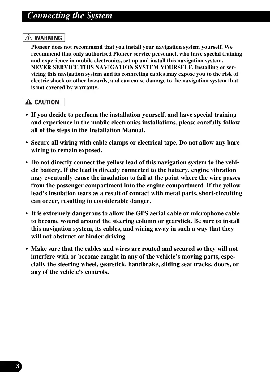
- Do not directly connect the yellow lead of this navigation system to the vehicle battery. If the lead is directly connected to the battery, engine vibration may eventually cause the insulation to fail at the point where the wire passes from the passenger compartment into the engine compartment. If the yellow lead's insulation tears as a result of contact with metal parts, short-circuiting can occur, resulting in considerable danger.
- It is extremely dangerous to allow the GPS aerial cable or microphone cable to become wound around the steering column or gearstick. Be sure to install this navigation system, its cables, and wiring away in such a way that they will not obstruct or hinder driving.
-
Make sure that the cables and wires are routed and secured so they will not interfere with or become caught in any of the vehicle's moving parts, especially the steering wheel, gearstick, handbrake, sliding seat tracks, doors, or any of the vehicle's controls.
-
Do not route wires where they will be exposed to high temperatures. If the insulation heats up, wires may become damaged, resulting in a short circuit or malfunction and permanent damage to the navigation system.
- Do not cut the GPS aerial cable to shorten it or use an extension to make it longer. Altering the aerial cable could result in a short circuit or malfunction.
- Do not shorten any leads. If you do, the protection circuit (fuse holder, fuse resistor or filter, etc.) may fail to work properly.
- Never feed power to other electronic products by cutting the insulation of the power supply lead of the navigation system and tapping into the lead. The current capacity of the lead will be exceeded, causing overheating.
- The black lead is earth. Please earth this lead separately from the earth of high-current products such as power amps. Do not earth more than one product together with the earth from another product. For example, you must separately earth any amplifier unit away from the earth of this navigation system. Connecting earths together can cause a fire and/or damage the products if their earths became detached.
Before installing this navigation system
- This navigation system is for vehicles with a 12-volt battery and negative earthing. Check the battery voltage of your vehicle before installation.
- To avoid shorts in the electrical system, be sure to disconnect the (−) battery cable before beginning installation.

natural_image
Illustration of a hand using a tool to switch a battery with terminals and power supply (no text or symbols)To prevent damage
- When disconnecting a connector, pull the connector itself. Do not pull the lead, as you may pull it out of the connector.
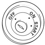
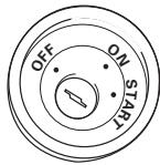
- This navigation system cannot be installed in a vehicle that does not have an ACC (accessory) position on the ignition switch.
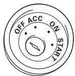
ACC position
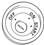
No ACC position
- When the “Auto ANT” mode is set to “Radio”, the vehicle’s aerial can be stowed or turned off by following the instructions below.
- Change the source from radio (AM or FM) to another source
– Turn the source off
– Turn off the ignition switch (ACC OFF)
- If the “Auto ANT” mode is set to “Power”, the vehicle’s aerial can be stowed or turned off only when the ignition switch is turned off (ACC OFF).
- When replacing the fuse, be sure to only use a fuse of the rating prescribed on the fuse holder.
- To avoid a short-circuit, cover the disconnected lead with insulating tape. Insulate the unused speaker leads without fail. There is a possibility of a short-circuit if the leads are not insulated.
- Attach the connectors of the same colour to the corresponding coloured port, i.e., blue connector to the blue port, black to black, etc.
- Refer to the owner's manual for details on connecting the power amp and other units, then make connections accordingly.
- Since a unique BPTL circuit is employed, do not directly earth the side of the speaker lead or connect the sides of the speaker leads together. Be sure to connect the side of the speaker lead to the side of the speaker lead on this navigation system.
- If the RCA pin jack on this navigation system will not be used, do not remove the caps attached to the end of the connector.
- Speakers connected to this navigation unit must be high-power with minimum rating of 50 W and impedance of 4 to 8 ohms. Connecting speakers with output and/or impedance values other than those noted here may result in the speakers catching fire, emitting smoke, or becoming damaged.
- When the ignition switch is turned on (ACC ON), a control signal is output through the blue/white lead. Connect to an external power amp's system remote control terminal (max. 300 mA 12 V DC). The control signal is output through the blue/white lead, even if the audio source is switched off.
- When an external power amp is being used with this system, be sure not to connect the blue lead to the amp's power terminal. Likewise, do not connect the blue lead to the power terminal of the auto aerial. Such connection could cause excessive current drain and malfunction as well as damage to the auto aerial of the vehicle.
Parts supplied
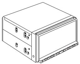
natural_image
Line drawing of a rectangular electronic device with mounting holes and a base plate (no text or symbols)The navigation unit
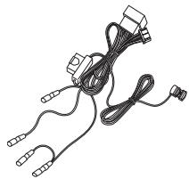
natural_image
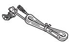
Line drawing of a cable and connector with connectors (no text or symbols)Power cord
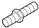
Connector
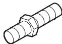
Extension lead (for reverse signal)
Extension lead (for speed signal)
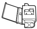
natural_image
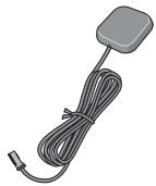
Illustration of a gray rectangular sensor or connector with a coiled cable and terminal connector (no text or symbols)GPS aerial

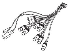
natural_image
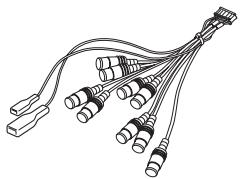
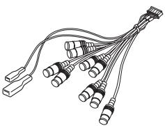
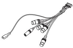
Line drawing of a multi-pin electrical connector with multiple leads (no text or symbols)RCA connector 1
(CONNECTOR 1)

natural_image
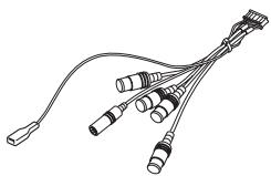
Line drawing of a multi-pin electrical connector with multiple leads (no text or symbols)RCA connector 2
(CONNECTOR 2)
natural_image
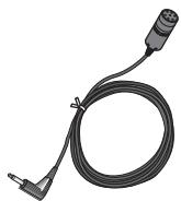
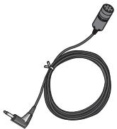
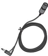
Coiled black cable with a terminal connector, no text or symbols visibleMicrophone
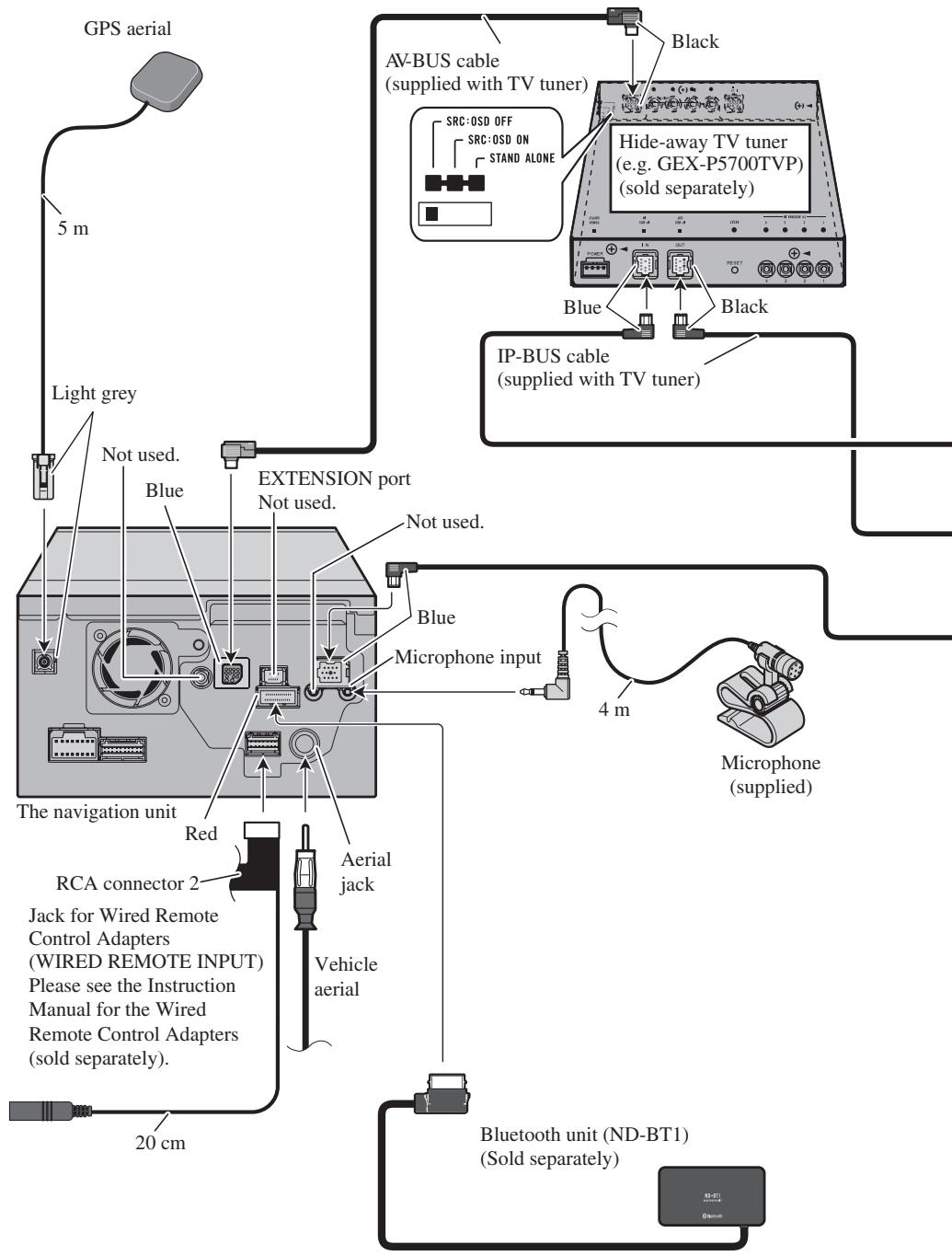
Connecting the system
Multi-CD player (sold separately)
WARNING
- To avoid the risk of accident and the potential violation of applicable laws, this navigation system should never be used while the vehicle is being driven except for navigation purposes. Also Rear Displays should not be in a location where it is a visible distraction to the driver.
- In some countries, the viewing of images on a display inside a vehicle even by persons other than the driver may be illegal. Where such regulations apply they must be obeyed and this navigation system's video source or TV features should not be used.
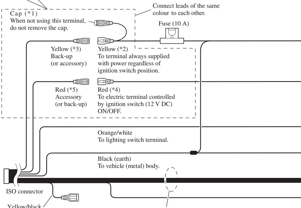
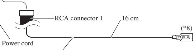
Connecting the power cord (1)
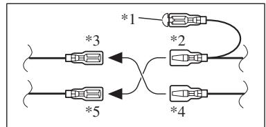
Note:
Depending on the kind of vehicle, the function of *3 and *5 may be different. In this case, be sure to connect *2 to *5 and *4 to *3.
flowchart
graph TD
    A["Component 1"] --> B["Component 2"]
    C["Component 3"] --> D["Component 4"]
    E["Component 5"] --> F["Component 4"]
    B --> G["Output"]
    D --> H["Output"]
    F --> I["Output"]
Note:
When a subwoofer (*9) is connected to this navigation system instead of a rear speaker, change the rear output setting in the Initial Setting. (Refer to the Operation Manual.) The subwoofer output of this navigation system is monaural.
When using a subwoofer of 70 W (2 Ω), be sure to connect with violet and violet/black leads of this navigation unit. Do not connect anything with green and green/black leads.
flowchart
graph TD
    A["Cap (*1)<br>When not using this terminal,<br>do not remove the cap."] --> B["Yellow (*3)<br>Back-up<br>(or accessory)"]
    A --> C["Red (*5)<br>Accessory<br>(or back-up)"]
    A --> D["Orange/white<br>To lighting switch terminal."]
    A --> E["Black (earth)<br>To vehicle (metal) body."]
    A --> F["Fuse (10 A)"]
    B --> G["Connect leads of the same colour to each other."]
    C --> H["To terminal always supplied with power regardless of ignition switch position."]
    D --> I["To electric terminal controlled by ignition switch (12 V DC) ON/OFF."]
    E --> J["Black (earth)<br>To vehicle (metal) body."]
    F --> K["Fuse (10 A)"]
    style A fill:#f9f,stroke:#333
    style B fill:#ccf,stroke:#333
    style C fill:#ccf,stroke:#333
    style D fill:#ccf,stroke:#333
    style E fill:#ccf,stroke:#333
    style F fill:#ccf,stroke:#333
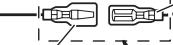
Yellow/black
If the vehicle can send a mute signal to this terminal, the mute function can be activated on this navigation system when the terminal is connected to *8.
Note:
In some vehicles, the ISO connector may be divided into two. In this case, be sure to connect to both connectors.
Speaker leads
White: Front left ⊕
White/black: Front left ⊖
Grey: Front right ⊕
Grey/black: Front right ⊖
Green: Rear left ⊕ or Subwoofer ⊕ (*9)
Green/black: Rear left ⊖ or Subwoofer ⊖ (*9)
Violet: Rear right ⊕ or Subwoofer ⊕ (*9)
Violet/black: Rear right ⊖ or Subwoofer ⊖ (*9)
The navigation unit
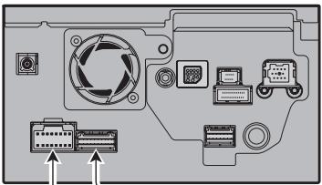
natural_image
Diagram of a computer monitor rear panel showing ports, connectors, and ventilation system (no text or labels)Note:
Cords for this navigation system and those for other products may be different colours even if they have the same function. When connecting this navigation system to another product, refer to the supplied manuals of both products and connect cords that have the same function.
Yellow/black (MUTE)
If you use equipment with a mute function, connect that equipment to the Audio Mute lead. If not, keep the Audio Mute lead free of any connections.
Note:
Audio source will be set to mute or attenuate, while the following sounds will not be muted or attenuated. For details, see the Operation Manual.
- voice guidance of the navigation
- incoming ringtone and incoming voice of the mobile phone that is connected to this navigation system via Bluetooth wireless technology
Note:
The aerial will automatically retract or turn off, yet the timing varies depending on the setting. (Refer to page 5.) For more detailed information on changing the “Auto ANT” mode, refer to “Switching the auto aerial setting” in the Operation Manual.
Blue (\*7)
To Auto-aerial relay control terminal. If the vehicle has a glass aerial, connect to the aerial booster power control terminal (max. 300 mA 12 V DC).
The pin position of the ISO connector will differ depending on the type of vehicle. Connect *6 and *7 when Pin 5 is an aerial control type. In other types of vehicle, never connect *6 and *7.
Connecting the power cord (2)
Speed detection circuit lead Vehicle injection \ Connector computer
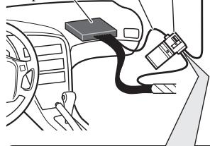
natural_image
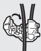
Diagram of a car interior showing wiring and components (no text or symbols)Connection method

Pass the extension cord and the lead for the speed detection circuit through this hole.

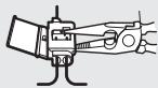
Clamp firmly with needle-nosed pliers.


Close the cover.
Pink (CAR SPEED SIGNAL INPUT)
The mobile navigation system is connected here to detect the distance the vehicle travels. Always connect the vehicle's speed detection circuit or the ND-PG1 speed pulse generator, sold separately. Failure to make this connection will increase errors in the location display.

WARNING
IMPROPER CONNECTION MAY RESULT IN SERIOUS DAMAGE OR INJURY INCLUDING ELECTRICAL SHOCK, AND INTERFERENCE WITH THE OPERATION OF THE VEHICLE'S ANTILOCK BRAKING SYSTEM, AUTOMATIC GEARBOX AND SPEEDOMETER INDICATION.

CAUTION
- It is strongly suggested that the speed pulse wire be connected for accuracy of navigation and better performance of interlock.
- If the speed pulse wire is unavailable for some reason, it is recommended that the pulse generator (ND-PG1) be used.
Note:
The position of the speed detection circuit and the position of the parking brake switch vary depending on the vehicle model. For details, consult your authorised Pioneer dealer or an installation professional.
Light green
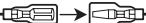
Used to detect the ON/OFF status of the handbrake. This lead must be connected to the power supply side of the handbrake switch.
If this connection is made incorrectly or omitted, certain functions of your navigation system will be unusable.

WARNING
LIGHT GREEN LEAD AT POWER CONNECTOR IS DESIGNED TO DETECT PARKED STATUS AND MUST BE CONNECTED TO THE POWER SUPPLY SIDE OF THE HANDBRAKE SWITCH. IMPROPER CONNECTION OR USE OF THIS LEAD MAY VIOLATE APPLICABLE LAW AND MAY RESULT IN SERIOUS INJURY OR DAMAGE.

Connection method
Clamp the parking brake switch power supply side lead.

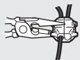
Clamp firmly with needle-nosed pliers.
Power supply side
Earth side
Handbrake switch
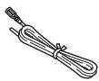
Extension lead (for speed signal)
5 m
Note:
Cords for this navigation system and those for other products may be different colours even if they have the same function. When connecting this navigation system to another product, refer to the supplied manuals of both products and connect cords that have the same function.
The navigation unit
Violet/white (REVERSEGEAR SIGNAL INPUT)
This is connected so that the navigation system can detect whether the vehicle is moving forwards or backwards. Connect the violet/white lead to the lead whose voltage changes when the reverse gear is engaged. Unless connected, the sensor may not detect your vehicle travelling forward/backward properly, and thus the position of your vehicle detected by the sensor may be misaligned from the actual position.
Yellow/black (GUIDE ON)
When combining this navigation system with the other Pioneer audio unit for the vehicle, if the vehicle stereo has yellow/black leads, connect them to those leads. In this way, the vehicle stereo is automatically muted to reduce the vehicle stereo volume when;
– the guidance audio is output.
– the mobile phone is used via Bluetooth unit.
– you operate the system by voice.
Note:
When you use the ND-PG1 speed pulse generator (sold separately), please make sure to connect this lead.
When you use a rear view camera, please make sure to connect this lead. Otherwise you cannot switch to rear view camera picture.
See Page 15.
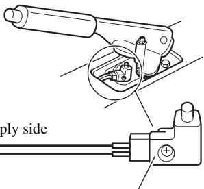
Connection method
Clamp the reversing lamp lead.
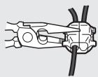

Clamp firmly with needle-nosed pliers.

CAUTION
Be sure to use only the supplied extension lead. Use of another lead could cause fire, smoke and/or damage this navigation system.
Reversing lamp lead
Extension lead (for reverse signal)
5 m
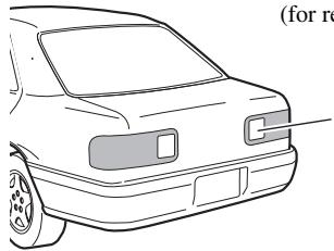
natural_image
Front view line drawing of a car (no text or symbols)Check the position of your vehicle's reversing lamp (the one that lights up when the gearstick is in reverse [R]) and find the reversing lamp lead in the boot.
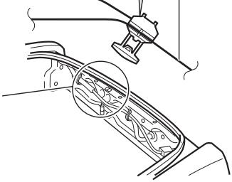
natural_image
Technical line drawing of a mechanical component with a magnified inset showing internal parts (no text or symbols)When connecting to separately sold power amp
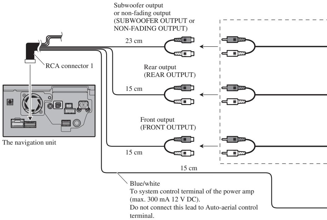
flowchart
graph TD
    A["The navigation unit"] --> B["RCA connector 1"]
    B --> C["Subwoofer output or non-fading output (SUBWOOFER OUTPUT or NON-FADING OUTPUT)"]
    C --> D["23 cm"]
    C --> E["15 cm"]
    C --> F["15 cm"]
    C --> G["15 cm"]
    C --> H["15 cm"]
    D <--> I["Rear output (REAR OUTPUT)"]
    E <--> J["Front output (FRONT OUTPUT)"]
    F <--> K["Blue/white To system control terminal of the power amp (max. 300 mA 12 V DC). Do not connect this lead to Auto-aerial control terminal."]
    G <--> L["Blue/white To system control terminal of the power amp (max. 300 mA 12 V DC). Do not connect this lead to Auto-aerial control terminal."]
Perform these connections when using the optional amplifier.
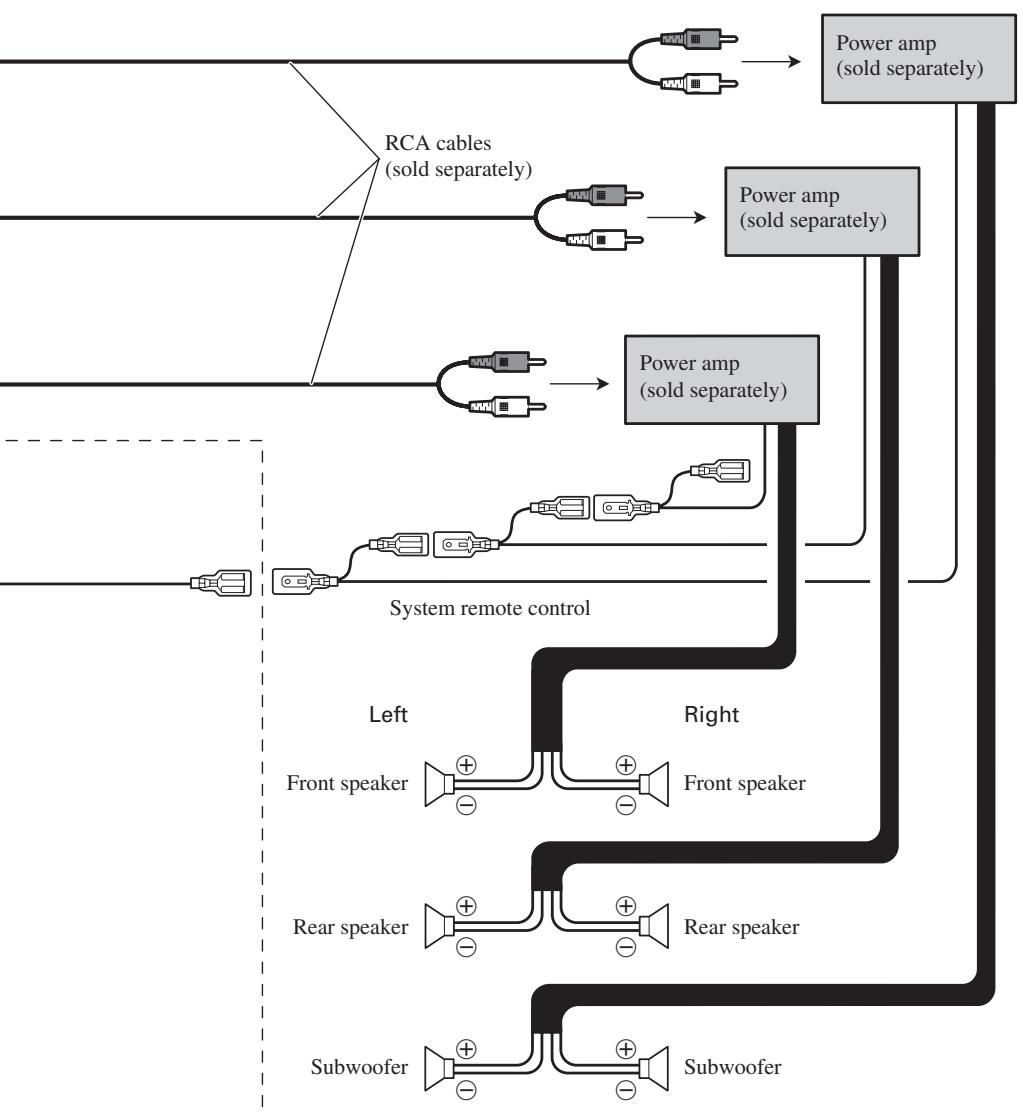
flowchart
graph TD
    A["Front speaker"] --> B["Subwoofer"]
    C["Rear speaker"] --> D["Subwoofer"]
    E["Back view"] --> F["Front speaker"]
    G["Central panel"] --> H["Central panel"]
    I["Power amp (sold separately)"] --> J["Power amp (sold separately)"]
    K["System remote control"] --> L["Power amp (sold separately)"]
    M["RCA cables (sold separately)"] --> N["RCA cables (sold separately)"]
    O["Power amp (sold separately)"] --> P["Power amp (sold separately)"]
    Q["Left/Right side labels"] --> R["Left/Right side labels"]
Note:
You can change the RCA output of the subwoofer depending on your subwoofer system. (Refer to the Operation Manual.)
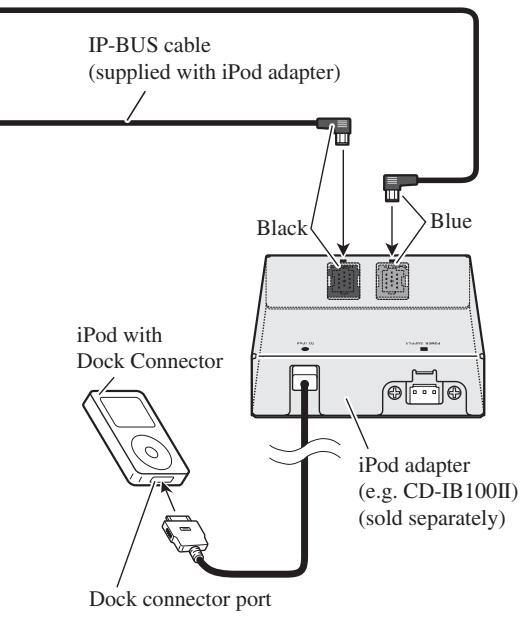
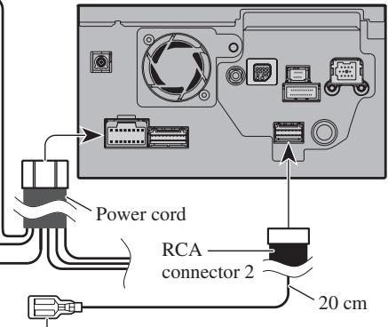
When connecting a rear view camera
When using this navigation system with a rear view camera, automatic switching to video from a rear view camera is possible when the gearstick is moved to REVERSE (R) position. Rear view mode also allows you to check what is behind you while driving.
WARNING
USE INPUT ONLY FOR REVERSE OR MIRROR IMAGE REAR VIEW CAMERA. OTHER USE MAY RESULT IN INJURY OR DAMAGE.
CAUTION
• The screen image may appear reversed.
- The rear view camera function is to use this navigation system as an aid to keep an eye on trailers, or backing into a tight parking spot. Do not use this function for entertainment purposes.
- The object in rear view may appear closer or more distant than in reality.
- Please note that the edges of the rear view camera images may differ slightly according to whether full screen images are displayed when backing, and whether the images are used for checking the rear when the vehicle is moving forward.
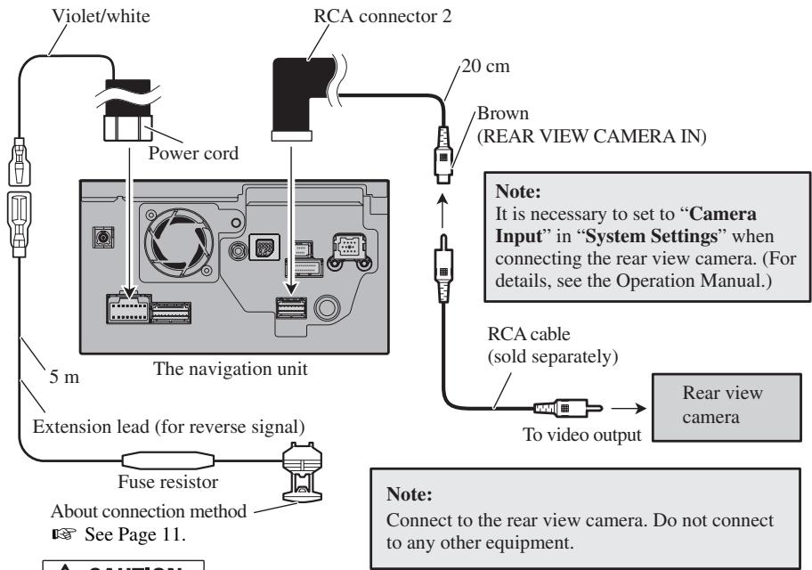
flowchart
graph TD
    A["Violet/white"] --> B["Power cord"]
    B --> C["The navigation unit"]
    C --> D["Fuse resistor"]
    D --> E["About connection method"]
    E --> F["See Page 11."]
    G["RCA connector 2"] --> H["20 cm"]
    H --> I["Brown (REAR VIEW CAMERA IN)"]
    I --> J["Note: It is necessary to set to "Camera Input" in "System Settings" when connecting the rear view camera. (For details, see the Operation Manual)."]
    J --> K["RCA cable (sold separately)"]
    K --> L["To video output"]
    L --> M["Rear view camera"]
    N["Note: Connect to the rear view camera. Do not connect to any other equipment."]
CAUTION
Be sure to use only the supplied extension lead. Use of another lead could cause fire, smoke and/or damage this navigation system.
When connecting the external video component
The navigation unit
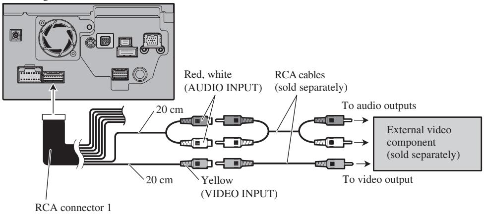
flowchart
graph LR
    A["Internal Display"] --> B["RCA connector 1"]
    B --> C["20 cm"]
    C --> D["Red, white (AUDIO INPUT)"]
    D --> E["20 cm"]
    E --> F["Yellow (VIDEO INPUT)"]
    F --> G["To video outputs"]
    G --> H["External video component (sold separately)"]
    H --> I["To video output"]
- It is necessary to set “AV Input” in “System Settings” to “Video” when connecting the external video component. (For details, refer to the Operation Manual.)
When connecting the external unit featuring video source
The navigation unit
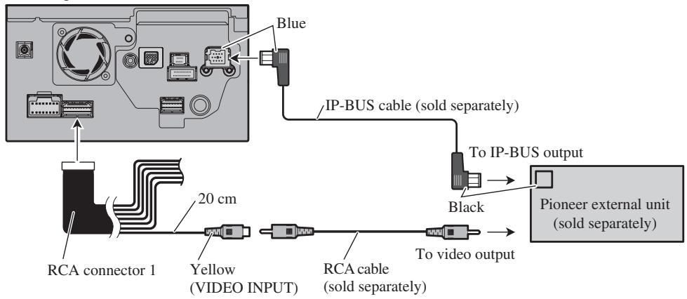
- It is necessary to set “AV Input” in “System Settings” to “EXT” when connecting the external video component. (For details, refer to the Operation Manual.)
When connecting the rear display
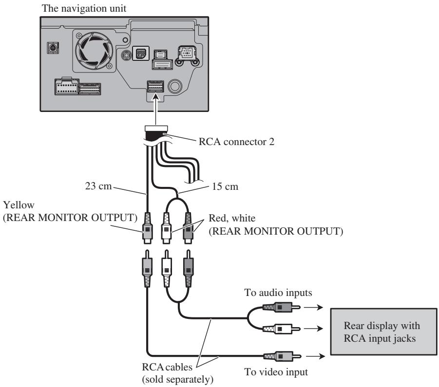
When using a rear display connected to rear video output
WARNING
NEVER install the rear display in a location that enables the driver to watch the video source while driving.
This navigation system's rear video output is for connection of a display to enable passengers in the rear seats to watch the video source. You can switch the rear screen mode in "AV Source Menu". (For details, refer to the Operation Manual.)
Notes:
- The map screen navigation images output to the rear display differ from standard NTSC format images. Therefore, their quality will be inferior to the images that appear on the front display.
- The navigation system automatically switches the colour system (NTSC, PAL, SECAM) for each video and outputs the video on the “Rear Display”. To correctly output each type of video on the “Rear Display”, we recommend using a “Rear Display” with a function to automatically switch the colour system (e.g. AVD-W1100V).
WARNING
Pioneer does not recommend that you install or service your navigation system yourself. Installing or servicing the navigation system may expose you to risk of electric shock or other hazards. Refer all installation and servicing of your navigation system to authorised Pioneer service personnel.
CAUTION
- Never install this navigation system in places where, or in a manner that:
* It could injure the driver or passengers if the vehicle stops suddenly.
* It may interfere with the driver's operation of the vehicle, such as on the floor in front of the driver's seat, or close to the steering wheel or gear-stick. - Make sure there is nothing behind the dashboard or panelling when drilling holes in them. Be careful not to damage fuel lines, brake lines, electronic components, communication wires or power cables.
- When using screws, do not allow them to come into contact with any electrical lead. Vibration may damage wires or insulation, leading to a short circuit or other damage to the vehicle.
- To ensure proper installation, use the supplied parts in the manner specified. If any parts other than the supplied ones are used, they may damage internal parts of this navigation system or they may work loose and the navigation system may become detached.
- It is extremely dangerous to allow the GPS aerial lead or microphone lead to become wound around the steering column or gearstick. Be sure to install this navigation system in such a way that it will not obstruct driving.
- Make sure that leads cannot get caught in a door or the sliding mechanism of a seat, resulting in a short circuit.
- Please confirm the proper function of your vehicle's other equipment following installation of the navigation system.
- Certain government laws may prohibit or restrict the placement and use of this system in your vehicle. Please comply with all applicable laws and regulations regarding the use, installation and operation of your navigation system.
-
Do not install this navigation system where it may (i) obstruct the driver's vision, (ii) impair the performance of any of the vehicle's operating systems or safety features, including airbags, hazard lamp buttons or (iii) impair the driver's ability to safely operate the vehicle.
-
Install this navigation system between the driver's seat and front passenger seat so that it will not be hit by the driver or passenger if the vehicle stops quickly.
- Never install this navigation system in front of or next to the place in the dash, door, or pillar from which one of your vehicle's airbags would deploy. Please refer to your vehicle's Owner's Manual for reference to the deployment area of the frontal airbags.
- Do not install this navigation system in a place where it will impair the performance of any of the vehicle's operating systems, including airbags and headrests.
To guard against electromagnetic interference
- In order to prevent interference, set the following items as far as possible from this navigation system, other cables or leads:
- TV aerial and aerial lead
- FM, MW/LW aerial and its lead
- GPS aerial and its lead
In addition you should lay or route each aerial lead as far as possible from other aerial leads.
Do not bind them together, lay or route them together, or cross them.
Such electromagnetic noise will increase the potential for errors in the location display.
Before installing
- Consult with your nearest dealer if installation requires the drilling of holes or other modifications of the vehicle.
- Before making a final installation of this navigation system, temporarily connect the wiring to confirm that the connections are correct and the system works properly.
- Do not install this navigation system in a position where the opening of the LCD panel is obstructed by any obstacles, such as the shift lever. Before installing this navigation system, be sure to leave sufficient space so that the LCD panel does not obstruct the shift lever when it is fully opened. This may cause interference with the shift lever, or a malfunction of the mechanism of this navigation system.
Installation notes
- Do not install this navigation system in places where it may become subject to high temperatures or humidity, such as:
* Places close to a heater, vent or air conditioner.
* Places exposed to direct sunlight, such as on top of the dashboard.
* Places that may be splashed by rain, for example close to the door.
- Install this navigation system in an area strong enough to bear its weight. Choose a position where this navigation system can be firmly installed, and install it securely. If this navigation system is not securely installed, the current location of the vehicle cannot be displayed correctly.
- Install the navigation system horizontally on a surface within 0 degrees to 30 degrees tolerance. If the installation angles on the left and right sides exceed 5 degrees, the allowable range can be increased to 10 degrees by making corrective adjustments. (Refer to “Correcting the installation angle” in the Operation Manual.) If connection of the pink lead (CAR SPEED SIGNAL INPUT) is omitted, the angles on the left and right sides are allowable to within five degrees. Improper installation of the unit with the surface tilted more than these tolerances increases the potential for errors in the location display, and might otherwise cause reduced display performance.
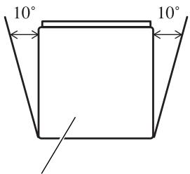
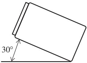
If the angle exceeds five degrees, please make corrective adjustments.
- The cords must not cover up the area shown in the figure below. This is necessary to allow the amplifiers and navigation mechanism to dissipate heat.
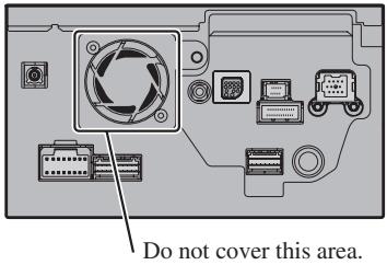
- The semiconductor laser will be damaged if it overheats, so don't install the navigation unit anywhere hot — for instance, near a heater outlet.
Parts supplied
Parts marked (*) are pre-installed.
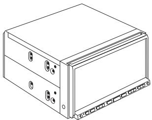
natural_image
Line drawing of a rectangular electronic device with multiple ports and connectors (no text or symbols)The navigation unit

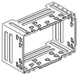
natural_image
Technical line drawing of a rectangular metal enclosure with internal compartments and mounting holes (no text or symbols)Holder*

natural_image
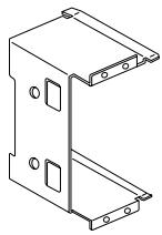
Technical line drawing of a mechanical bracket or mounting plate (no text or symbols)Side bracket ^* (2 pcs.)

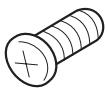
Binding screw (5 × 6 mm) (8 pcs.)

Flush surface screw (5 × 6 mm) (4 pcs.)
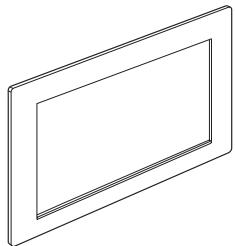
natural_image
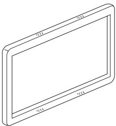
Simple line drawing of a rectangular frame with no text or symbolsFrame
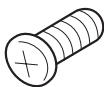
Screw ^* (3 × 6 mm)
(8 pcs.)

Screw for fixing the side bracket* (5 × 6 mm) (4 pcs.)
natural_image
Isometric line drawing of a rectangular electronic device with labeled dimensions (no text or symbols)Trim ring

Double-ended screw

Rubber bush
Before installing this navigation unit
- Remove the holder.
Loosen the screws (3 × 6 mm) to remove the holder.
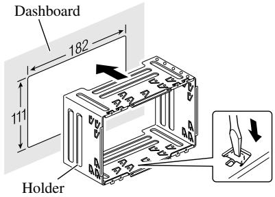
Installation with the holder and side bracket
1. Install the holder into the dashboard.
After inserting the holder into the dashboard, select and bend the tabs appropriate to the thickness of the dashboard material. (Install this navigation unit as firmly as possible using the top and bottom tabs. To secure this navigation unit, bend the tabs 90 degrees.)
2. Install this navigation unit and fasten the screws.
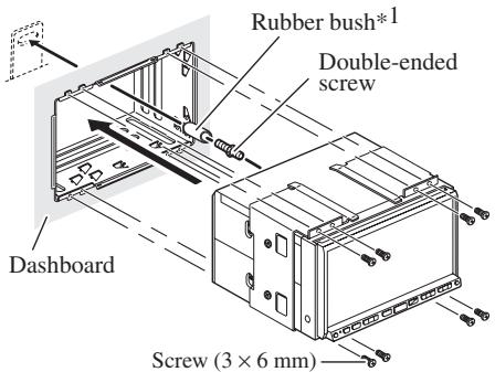
Be sure to attach the rubber bush to the long end of double-ended screw.
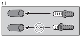
3. Attach the trim ring.
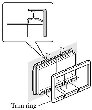
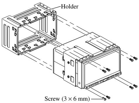
Installation using the screw holes on the side of the navigation unit
1. Remove the side brackets.
2. Fastening the navigation unit to the factory radio-mounting bracket.
Position the navigation unit so that its screw holes are aligned with the screw holes of the bracket, and tighten the screws at 3 or 4 locations on each side. Use either the binding screws (5 × 6 mm) or flush surface screws (5 × 6 mm), depending on the shape of the bracket's screw holes.
natural_image
Pure electrical circuit lines without any symbols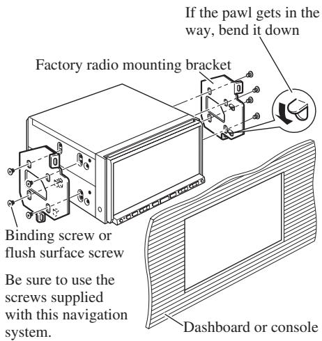
Note:
In some types of automobiles, discrepancy may occur between the navigation unit and the dashboard. If this happens, use the supplied frame to fill the gap.
CAUTION
- Do not cut the GPS aerial lead to shorten it or use an extension to make it longer. Altering the aerial cable could result in a short circuit or malfunction and permanent damage to the navigation system.
Installation notes
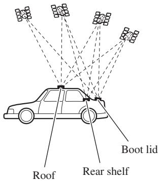
- The aerial should be installed on a level surface where radio waves will be blocked as little as possible. Radio waves cannot be received by the aerial if reception from the satellite is blocked.
Installation on the vehicle roof or boot lid is recommended to optimise reception.
- When installing the GPS aerial inside the vehicle, be sure to use the metal sheet provided with your system. If this is not used, the reception sensitivity will be poor.
- Do not cut the accessory metal sheet. This would reduce the sensitivity of the GPS aerial.
- Take care not to pull the aerial lead when removing the GPS aerial. The magnet attached to the aerial is very powerful, and the lead may become detached.
- The GPS aerial is installed with a magnet. When installing the GPS aerial, be careful not to scratch the vehicle body.
- When installing the GPS aerial on the outside of the vehicle, always put it in the vehicle when going through an automatic vehicle wash. If it is left on the outside it may be knocked off and scratch the vehicle body.
- Do not paint the GPS aerial, as this may affect its performance.
Parts supplied
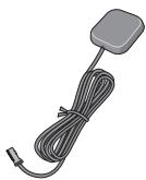
natural_image
Illustration of a gray rectangular sensor or connector with a coiled cable and terminal connector (no text or symbols)GPS aerial

Metal sheet

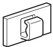
Clamp (5 pcs.)

Waterproof pad
When installing the aerial inside the vehicle (on the rear shelf)
Affix the metal sheet on as level a surface as possible where the GPS aerial faces the window. Place the GPS aerial on the metal sheet. (The GPS aerial is fastened with its magnet.)
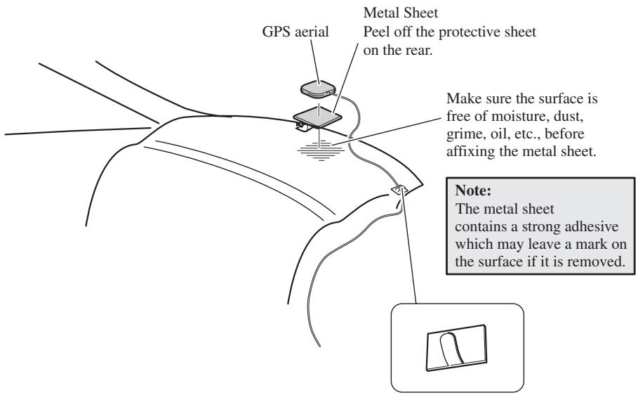
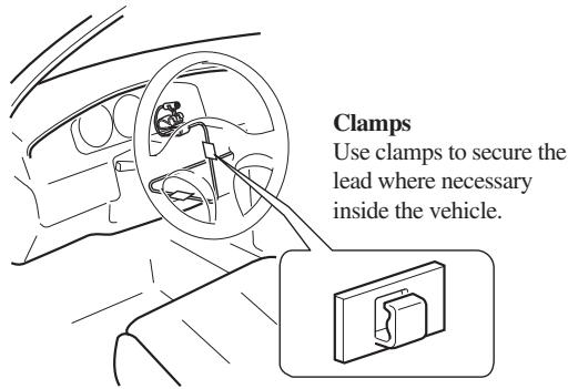
Clamps
Use clamps to secure the lead where necessary inside the vehicle.
Notes:
- When attaching the metal sheet, do not cut it into small pieces.
- Some models use window glass that does not allow signals from GPS satellites to pass through. On such models, install the GPS aerial on the outside of the vehicle.
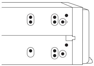
When installing the aerial outside the vehicle (on the body)
Put the GPS aerial in a position as level as possible, such as on the roof or boot lid. (The GPS aerial is fastened with a magnet.)
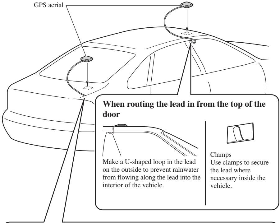
When routing the lead in from inside the boot
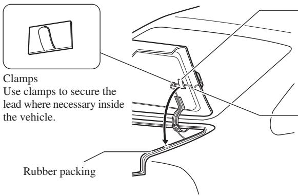
Waterproof pad Make sure the waterproof pad contacts the top of the rubber packing.
Make a U-shaped loop in the lead outside the rubber packing to prevent rainwater from flowing along the lead into the interior of the vehicle.
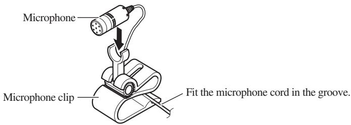
Installing the microphone
- Install the microphone in a place where its direction and distance from the driver make it easiest to pick up the driver's voice.
- Make sure to connect the microphone to the navigation system after the system is turned off. (ACC OFF)
Parts supplied
natural_image
Illustration of a black cable with a connector and terminal connector (no text or symbols)Microphone
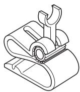
natural_image
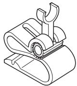
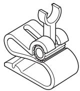
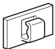
Technical line drawing of a mechanical clamp or bracket assembly (no text or symbols)Microphone clip

Double-sided tape
Clamp (5 pcs.)
Mounting on the sun visor
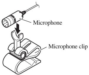
1. Install the microphone in the microphone clip.
2. Attach the microphone clip to sun visor.
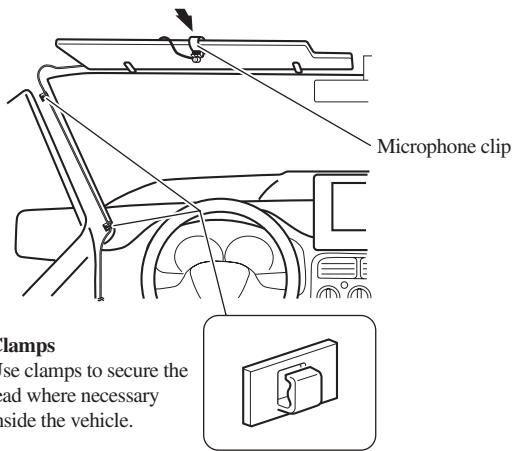
Install the microphone on the sun visor when it is in the up position. It cannot recognise the driver's voice if the sun visor is in the down position.
Installation on the steering column
1. Install the microphone in the microphone clip.
2. Mount the microphone clip on the steering column.
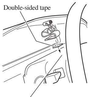
Install the microphone clip on the steering column, keeping it away from the steering wheel.
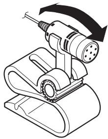
Adjusting the microphone angle
The microphone angle can be adjusted by moving forward or backward the microphone clip angle.
natural_image
Technical line drawing of a mechanical device with a rotating shaft and housing (no text or symbols)1. Reconnecting the battery.
First, double-check that all connections are correct and that this navigation system is installed correctly. Reassemble all vehicle components that you previously removed. Then reconnect the negative (−) cable to the negative (−) terminal of the battery.
2. Start the engine.
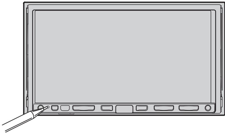
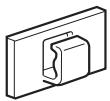
3. Press the RESET button on the navigation unit.
Press the RESET button on the navigation system using a pointed object such as the tip of a pen.
natural_image
Line drawing of a blank electronic device with a hand pointing to the left side (no text or symbols)4. Enter the following settings:
- Make any necessary installation angle adjustments. (Refer to “Correcting the installation angle” in “Chapter 9” of the Operation Manual.)
- Change “Regional Settings” if necessary. (Refer to “Customising the Regional Settings” in “Chapter 9” of the Operation Manual.)
- Drive until the initialised sensors start operating normally.
Set the navigation system as explained in the Operation Manual or Hardware Manual.
After installing this navigation system, be sure to check at a safe place that the vehicle is performing normally.
ACERCA DE ESTE MANUAL
natural_image
Illustration of a hand inserting a plug into a battery with a switch (no text or symbols)Para impedir daños
Posición ACC

Sin posición ACC
natural_image
Isometric line drawing of a rectangular electronic device with two ports and a base plate (no text or symbols)natural_image
Line drawing of a cable and connector with connectors (no text or symbols)natural_image
Illustration of a gray rectangular sensor or connector with a coiled cable and terminal connector (no text or symbols)Antena GPS
natural_image
Line drawing of multiple cable connectors with connectors and wires (no text or symbols)Conector RCA 1
(CONNECTOR 1)

natural_image
Line drawing of a multi-pin electrical connector with multiple leads (no text or symbols)Conector RCA 2
(CONNECTOR 2)

natural_image
Coiled black cable with two connectors, no text or symbols visibleMicrófono
natural_image
Diagram of a computer monitor rear panel with labeled components and directional arrows (no text or symbols)Nota:
natural_image
Line drawing of a rectangular electronic device with multiple ports and connectors (no text or symbols)natural_image
Isometric line drawing of a rectangular electronic enclosure with mounting holes and internal slots (no text or symbols)Soporte*

natural_image
Technical line drawing of a metal bracket with mounting holes and mounting holes (no text or symbols)natural_image
Simple line drawing of a rectangular frame with no text or symbolsMarco

Tornillo ^* (3 × 6 mm)
(8 piezas)
natural_image
Isometric line drawing of a rectangular electronic device with labeled dimensions (no text or symbols)Anillo embellecedor
Tornillo de doble punta

Cojinete de goma
natural_image
Pure electrical circuit lines without any symbols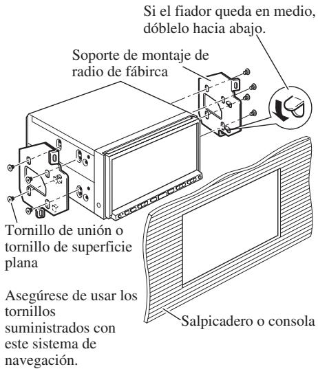
natural_image
Illustration of a gray rectangular sensor or connector with a coiled cable and terminal connector (no text or symbols)Antena GPS

Hoja de metal
natural_image
Coiled black cable with a terminal connector, no visible text or symbolsMicrófono

natural_image
Technical line drawing of a mechanical clamp or bracket assembly (no text or symbols)Clip del micrófono

Cinta de doble cara
natural_image
Technical line drawing of a mechanical device with a rotating shaft and housing (no text or symbols)natural_image
Line drawing of a flat-screen monitor with a pointing button, no text or symbols presentnatural_image
Illustration of a hand using a tool to switch a battery with terminals and power supply (no text or symbols)ACC-Stellung
Keine ACC-Stellung
natural_image
Line drawing of a rectangular electronic device with two side panels and mounting holes (no text or symbols)natural_image
Line drawing of a cable and connector with connectors (no text or symbols)Netzkabel

Anschluss
natural_image
Illustration of a gray rectangular sensor or connector with a coiled cable and terminal connector (no text or symbols)GPS-Antenne
natural_image
Line drawing of a multi-pin electrical connector with multiple leads (no text or symbols)Cinch-Anschluss 1
(CONNECTOR 1)
natural_image
Line drawing of a multi-pin connector with multiple leads (no text or symbols)Cinch-Anschluss 2
(CONNECTOR 2)
natural_image
Coiled black cable with a terminal connector, no text or symbols visibleMikrofon
natural_image
Diagram of an electronic device rear panel with connectors and ports (no text or labels)Hinweis:
Gelb/schwarz (GUIDE ON)
natural_image
Front view line drawing of a car (no text or symbols)natural_image
Line drawing of a rectangular electronic device with multiple ports and connectors (no text or symbols)natural_image
Technical line drawing of a rectangular metal enclosure with internal compartments and mounting holes (no text or symbols)Halterung*

natural_image
Technical line drawing of a mechanical bracket or mounting plate (no text or symbols)natural_image
Simple line drawing of a rectangular frame with no text or symbolsRahmen
natural_image
Isometric line drawing of a rectangular electronic device with labeled dimensions (no text or symbols)Abdeckring
natural_image
Pure electrical circuit lines without any symbolsnatural_image
Illustration of a gray rectangular sensor or connector with a coiled cable and terminal plug (no text or symbols)GPS-Antenne

Metallblech
natural_image
Coiled black cable with a terminal connector, no text or symbols visibleMikrofon
natural_image
Technical line drawing of a mechanical clamp or bracket assembly (no text or symbols)Mikrofon-Clip
natural_image
Technical line drawing of a mechanical device with a tool and rotating component (no text or symbols)natural_image
Line drawing of a blank electronic device with a hand pointing to its side panel (no text or symbols)AU SUJET DE CE MANUEL
natural_image
Illustration of a hand holding a battery with a switch, no text or symbols presentPosition ACC

Pas de position ACC
natural_image
Line drawing of a rectangular electronic device with mounting holes and a base plate (no text or symbols)Unité de navigation

natural_image
Line drawing of a cable and connector with connectors (no text or symbols)natural_image
Illustration of a gray rectangular sensor or connector with a coiled cable and terminal connector (no text or symbols)Antenne GPS
natural_image
Line drawing of a multi-pin electrical connector with multiple leads (no text or symbols)natural_image
Line drawing of a multi-pin electrical connector with multiple leads (no text or symbols)natural_image
Coiled black cable with a terminal connector, no text or symbols visibleMicrophone
natural_image
Diagram of a computer monitor rear panel showing ports, connectors, and ventilation system (no text or labels)Remarque :
natural_image
Front view line drawing of a car (no text or symbols)natural_image
Line drawing of a rectangular electronic device with multiple ports and connectors (no text or symbols)Unité de navigation
natural_image
Technical line drawing of a rectangular metal enclosure with internal compartments and mounting holes (no text or symbols)Support*

natural_image
Technical line drawing of a mechanical bracket or mounting plate (no text or symbols)natural_image
Simple line drawing of a rectangular frame with no text or symbolsCadre
natural_image
Isometric line drawing of a rectangular electronic device with labeled dimensions (no text or symbols)Anneau de garniture
Vis à deux bouts

Bague en caoutchouc
natural_image
Pure electrical circuit lines without any symbolsnatural_image
Illustration of a gray rectangular sensor or connector with a coiled cable and terminal connector (no text or symbols)Antenne GPS

Plaque métallique
natural_image
Illustration of a black cable with a connector and terminal connector (no text or symbols)Microphone
natural_image
Technical line drawing of a mechanical clamp or bracket assembly (no text or symbols)Clip Micro

Bande adhésive double-face
Crochet-support (5 pces.)
natural_image
Technical line drawing of a mechanical device with a rotating shaft and housing (no text or symbols)natural_image
Line drawing of a blank electronic device with a hand pointing to its side panel (no text or symbols)natural_image
Illustration of a hand using a power tool to switch an open battery (no text or symbols visible)Per evitare danni
Posizione ACC
natural_image
Line drawing of a rectangular electronic device with two side panels and mounting holes (no text or symbols)natural_image
Line drawing of a cable and connector with connectors (no text or symbols)natural_image
Illustration of a gray rectangular sensor or connector with a coiled cable and terminal connector (no text or symbols)Antenna GPS

natural_image
Line drawing of a multi-pin electrical connector with multiple leads (no text or symbols)natural_image
Line drawing of a multi-pin electrical connector with multiple leads (no text or symbols)natural_image
Coiled black cable with a terminal connector, no text or symbols visibleMicrofono
natural_image
Diagram of a computer monitor rear panel with labeled components and directional arrows (no text or symbols)Nota:
natural_image
Diagram of a car interior with a switch connected to a device, no text or symbols presentnatural_image
Technical line drawing of two mechanical clamping or fastening components (no text or symbols)natural_image
Front view line drawing of a car with no visible text or symbolsnatural_image
Line drawing of a rectangular electronic device with multiple ports and connectors (no text or symbols)natural_image
Technical line drawing of a rectangular metal enclosure with internal compartments and mounting holes (no text or symbols)Supporto*

natural_image
Technical line drawing of a mechanical bracket or mounting plate (no text or symbols)Staffa laterale ^* (2 pezzi)
natural_image
Simple line drawing of a rectangular frame with no text or symbolsCornice

Vite ^* (3 × 6 mm)
(8 pezzi)
natural_image
Isometric line drawing of a rectangular electronic device with labeled dimensions (no text or symbols)Anello di finitura
natural_image
Pure electrical circuit lines without any symbolsnatural_image
Illustration of a gray rectangular sensor or connector with a coiled cable and terminal connector (no text or symbols)Antenna GPS

Lastra metallica

Morsetto (5 pz.)

Pannello impermeabile
natural_image
Coiled black cable with a terminal connector, no visible text or symbolsMicrofono

natural_image
Technical line drawing of a mechanical clamp or bracket assembly (no text or symbols)natural_image
Technical line drawing of a mechanical device with a rotating shaft and housing (no text or symbols)1. Ricollegare la batteria.
natural_image
Line drawing of a blank electronic device with a hand pointing to the left side (no text or symbols)natural_image
Illustration of a hand holding a battery with a switch, no text or symbols presentACC stand

Geen ACC stand
natural_image
Isometric line drawing of a rectangular electronic device with two ports and a base (no text or symbols)natural_image
Line drawing of a cable and connector with connectors (no text or symbols)natural_image
Illustration of a gray rectangular sensor or connector with a coiled cable and terminal plug (no text or symbols)GPS-antenne

natural_image
Line drawing of a multi-pin electrical connector with multiple leads (no text or symbols)RCA connector 1
(CONNECTOR 1)
natural_image
Line drawing of a multi-pin electrical connector with multiple leads (no text or symbols)RCA connector 2
(CONNECTOR 2)

natural_image
Coiled black cable with a terminal connector, no text or symbols visibleMicrofoon
natural_image
Diagram of a computer motherboard showing ports and connectors (no text or labels)Opmerking:
Handremschakelaar
natural_image
Front view line drawing of a car (no text or symbols)natural_image
Line drawing of a rectangular electronic device with multiple ports and connectors (no text or symbols)natural_image
Isometric line drawing of a rectangular electronic enclosure or housing with mounting holes and internal slots (no text or symbols)Houder*
natural_image
Technical line drawing of a metal bracket with mounting holes and mounting holes (no text or symbols)natural_image
Simple line drawing of a rectangular frame with no text or symbolsFrame
Schroef ^* (3 × 6 mm)
(8 st.)
natural_image
Isometric line drawing of a rectangular electronic device with labeled dimensions (no text or symbols)Sierring

Tweezijdige schroef

Rubbermof
natural_image
Pure electrical circuit lines without any symbols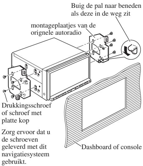
natural_image
Illustration of a gray rectangular sensor or connector with a coiled cable and terminal connector (no text or symbols)GPS-antenne

Metalen plaatje

Klem (5 st.)
natural_image
Illustration of a black cable with a connector and terminal connector (no text or symbols)Microfoon

natural_image
Technical line drawing of a mechanical clamp or bracket assembly (no text or symbols)Microfoonklem

Dubbelzijdig tape
Klem (5 stuks)
natural_image
Technical line drawing of a mechanical device with a rotating shaft and housing (no text or symbols)natural_image
Line drawing of a blank electronic device with a pointing button, no text or symbols presentPIONEER ELECTRONICS (USA) INC.
P.O. Box 1540, Long Beach, California 90801-1540, U.S.A.
TEL: (800) 421-1404
PIONEER EUROPE NV
Haven 1087, Keetberglaan 1, B-9120 Melsele, Belgium
TEL: (0) 3/570.05.11
Published by Pioneer Corporation.
Copyright © 2006 by Pioneer Corporation.
All rights reserved.
Publication de Pioneer Corporation.
Copyright © 2006 Pioneer Corporation.