
SF 40 - Flash LEICA - Free user manual and instructions
Find the device manual for free SF 40 LEICA in PDF.


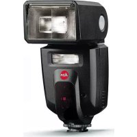
| Product type | Flash |
| Brand | Leica |
| Model | SF 40 |
| Dimensions (W x H x D) | Approx. 61 x 85 x 85 mm (head forward) / 61 x 133 x 57 mm (head up) |
| Weight (without batteries) | Approx. 200 g |
| Power supply | 4 AA batteries (LR6/FR6/HR6) |
| Guide number (ISO 100, 105 mm) | 40 m |
| Operating modes | A (auto), TTL, M (manual), SD/SF (wireless) |
| Zoom reflector | 24-105 mm (auto or manual) |
| Built-in wide-angle diffuser | 16 mm |
| Bounce flash | Head swivels horizontally (180°) and tilts vertically (90°) |
| Built-in video light | Yes, max. lighting duration 3.5 h (with lithium batteries) |
| AF assist light | Yes, range 0.70-5 m (with 50 mm lens) |
| Sync | HSS, slow sync, first/second curtain |
| Color temperature | Approx. 5600 K |
| ISO range | ISO 50 - 50,000 |
| Flash duration (full power) | 1/800 s |
| Auto power off | 2-5 min (standby mode), 60 min (complete shut-off) |
| Accessories | Snap-on diffuser (422-310.003-006), stand (422-310.003-005), case (439-600.243-000) |
| Care and cleaning | Soft dry cloth, never use cleaning liquid |
| Safety instructions | Do not flash into eyes, avoid flammable gases, risk of burns at diffuser, internal high voltage |
Frequently Asked Questions - SF 40 LEICA
User questions about SF 40 LEICA
0 question about this device. Answer the ones you know or ask your own.
Ask a new question about this device
Download the instructions for your Flash in PDF format for free! Find your manual SF 40 - LEICA and take your electronic device back in hand. On this page are published all the documents necessary for the use of your device. SF 40 by LEICA.
USER MANUAL SF 40 LEICA
Attention:
Notes:
Product Support/Software Support
Am Leitz-Park 5
D-35578 Wetzlar
Phone: +49(0)6441-2080-111 /-108
Fax: +49(0)6441-2080-490
info@leica-camera.com/software-support@leica-camera.com
LEICA CUSTOMER CARE
Leica would like to thank you for purchasing the Leica SF 40 system flash unit and to congratulate you on your choice. With this flash unit you have made the best choice for your Leica camera. We wish you a great deal of fun and success with your new flash unit.
Please read these instructions in their entirety so that you can make the most of your Leica SF 40.
MEANING OF DIFFERENT INSTRUCTION CATEGORIES
Note:
Additional information
Important:
Failure to observe the instructions may cause damage to the camera, accessories or the photos.
Caution:
Failure to observe the instructions may cause personal injury.
COMPATIBLE CAMERAS
The Leica SF 40 has been developed for Leica cameras that control the flash exposure themselves. This is done on the basis of a TTL (Through The Lens) flash internal measurement, as with the Leica digital cameras in the S, SL, M, T, Q and X series.
Naturally, the Leica SF 40 can also be used on other Leica models. Manual mode is available for this.
Use of the Leica SF 40 on cameras from other manufacturers, however, can only be recommended with reservations. For example, contacts in the accessory shoes of other cameras that are in a similar position but with different electrical values may result in an incompatible connection that affects one - or even both - of the devices. Leica Camera AG therefore excludes any further reaching liability, in particular for damage that did not occur on the flash unit itself.
Note:
The production date of your flash unit can be found on the stickers in the Guarantee Card and/or on the packaging. It is written L Y M DD XXXXXXX:
| L | = Leica |
| Y | = Year (1-0 (=2011-2020)) |
| M | = Month (1-9 = Jan.-Sept., A= Oct., B=Nov., C=Dec.) |
| DD | = Day (0-31) |
| XXXXXXXX | = firmware version |
TABLE OF CONTENTS
Foreword 25
Compatible cameras 25
Camera-type-dependent functions....27
Safety notes 28
Disposal of electrical and electronic equipment 30
Designation of parts 31
Preparations
Power supply 32
Changing the power source 32
Battery disposal 33
Attaching/removing the flash unit 34
Operation
Switching on and off 35
Displays when the flash unit is switched on ....35
Auto power OFF 35
Zoom reflector 36
Manual adjustment 36
Wide-angle diffusion head 37
Flash modes 39
Fully automatic - A 39
Fully automatic - TTL....39
Flash exposure compensation 40
Video light 40
Setting light intensity....40
Manual flash operation - M 41
Setting partial light output stages 41
Wireless operation 41
Further settings/functions
Indirect flash 43
Indirect flash with the reflector card 43
Slip-on diffusion head 44
AF auxiliary light 44
Appendix
Maintenance and care 45
Formation of the flash capacitor 45
Troubleshooting 45
Spare parts 46
Technical data 47
Leica Service addresses 48
Guide number table ......Appendix
Notes:
- The descriptions in this manual are largely limited to use of the Leica SF 40 and with Leica cameras of currently available series.
- In this manual, only those functions are described that the user sets himself/herself on the flash unit. With a few exceptions, this also applies to displays on the flash unit.
Please therefore follow the notes on flash operation in the manual of the camera used, in particular which flash functions are supported by your camera, as well as those referring to the flash-related settings on the camera and, if available, the camera's own flash-related displays.
CAMERA TYPE-DEPENDENT FUNCTIONS
The flash functions listed below are available (sometimes depending on the equipment of the camera system used).
- Flash readiness display in the camera viewfinder/on the monitor – Automatic flash synchronization control
- TTL flash mode
- Automatic fill-in flash control
- Manual flash exposure compensation
- Synchronization to the start of the end of the exposure time (setting on the camera) – Automatic high-speed synchronization with
- Automatic control of the zoom reflector
- Preflash function to reduce the "red-eye effect" (setting on the camera)
- Wireless release for flash operation remote from the camera
- Permanent light for video shots
- Automatic switch-off function
Note:
When using lenses or cameras that do not allow any data transfer between each other, i.e. that do not have any relevant interfaces in the bayonet, there may be some restrictions to function.
SAFETY NOTES
Caution:
Correct use
- This flash unit is intended only to light up subjects in the photographic field, and is licensed only for this. It must not be used for any other purpose.
- It may be operated only with the accessories described in this manual or with accessories approved by Leica Camera AG.
- The flash unit must never be triggered near flammable gases or liquids (gasoline, solvents, etc.)! There is a risk of EXPLOSION or FIRE!
- Never use the flash at close quarters direct into eyes because this can cause retinal damage to both people and animals and result in severe vision problems or even blindness!
- Bus, train or car drivers, or cyclists, should never be photographed with flash because an accident may be caused by dazzling the driver/cyclist! Before taking such shots, switch the flash off or make sure that the flash will not be triggered!
- Do not touch the diffusion head after repeated use of the flash as it can become very hot! There is a risk of burning!
- Do not touch the contact at the shoe of the flash unit either.
- If the device housing has been damaged so badly that internal parts are exposed, please do not touch them - HIGH VOLTAGE!
- This also applies if water or other liquids, metallic or flammable objects have penetrated the inside of the device.
- In this case, remove the batteries. Do this extremely carefully!
- The high-voltage circuit can cause electric shocks, burns or other injuries even after the batteries have been removed!
- For the same reason, you must never expose the device to moisture, such as drops or splashes of water, nor touch it with wet hands, or try to dismantle, repair or rebuild it! There are no components inside that can be repaired by an amateur.
- Only use the batteries named and approved in this manual!
- Batteries must not be short-circuited, or exposed to excessive heat, such as sunshine, fire, etc.! • Used batteries must never be thrown in a fire!
- Dry batteries ("primary cells") must not be charged.
Important:
- Protect your flash unit against excess heat and humidity! Do not store it in the glove compartment of your car!
- If the temperature changes quickly, condensation may form. Allow the flash unit to acclimatize!
- When a flash is fired, no opaque material should be immediately in front of or directly on the reflector head. It must not be dirty. If this is ignored, the material or the reflector head may be burned due to the high energy of the flash burst.
- This flash unit should only be used together with the camera's built-in unit if the latter is completely retracted! Faulty batteries should not be used!
- Alkaline solution can leach out of used batteries, which damages the contacts. Therefore, always remove them from the unit.
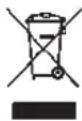
DISPOSAL OF ELECTRICAL AND ELECTRONIC EQUIPMENT
(Applies within the EU, and for other European countries with segregated waste collection systems)
This device contains electrical and/or electronic components and must therefore not be disposed of in general household waste! Instead, it should be disposed of at a recycling collection point provided by the local authority. This costs you nothing.
If the device contains standard or rechargeable batteries, these must be removed first and also be disposed of in line with relevant regulations. Further information on the subject is available from your local administration, your local waste collection company, or in the store where you purchased this device.
Note:
Within the scope of CE labeling, the correct exposure was evaluated in the EMC testing.

Do not touch SCA contacts!
In exceptional cases, touching can damage the device.
DESIGNATION OF PARTS
1 Reflector head, with
a Screen
b Reflector card
c Wide-angle diffusion screen
2 Video light
3 Sensor for wireless operation (behind infrared-permeable housing case)
4 AF auxiliary light
5 Foot with
a Release button
b Locking pin
6 Main switch
7 Pilot LED/test flash button
8 Mode selector dial with
a Index LED
9 Setting dial with
a Output level scale
b Status LED (also setting index)
c Flash exposure compensation scale
d Status LED (also setting index)
10 Battery compartment cover
11 Slip-on diffusion attachment
12 Pedestal with 1/4" thread
PREPARATIONS
POWER SUPPLY
This flash unit can be operated with the following power sources:
- 4 Alkaline-Manganese batteries 1.5 V, type IEC LR6 (AA/Mignon)
Batteries of this type are maintenance-free and suitable for moderate performance requirements.
- 4 Lithium batteries 1.5 V, type IEC FR6 (AA/Mignon)
Batteries of this type are maintenance-free, have high capacity and low self-discharge.
- 4 Nickel-metal-hydride rechargeable batteries 1.2 V, type IEC HR6 (AA/Mignon)
Rechargeable batteries of this type have a much higher capacity than Nickel-Cadmium rechargeable batteries and are less
harmful to the environment because they contain no Cadmium.
Details on the capacities of the various batteries can be found on p. 47
Important:
- Use only the above-mentioned power sources. If you use other power sources, there is a risk of damage to the flash unit.
- Always remove the batteries if you will not be using the flash unit for a long period of time.
CHANGING THE POWER SOURCE
The batteries are drained or spent when the flash recycle time rises to over 30s. (flash recycle time = time from firing the flash at full output, e.g. at M, to the pilot LED 7 lighting up in green again).
Procedure
- Switch off the flash unit (see the next section)
- Push the battery compartment cover to the front and let go. It then automatically folds up.
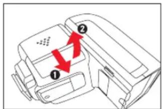
- Replace/insert batteries in accordance with the illustration. Pay attention to the correct polarity!
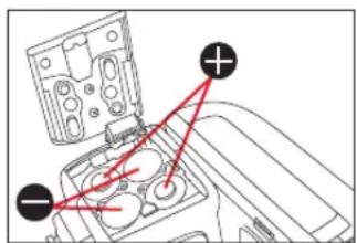
Caution:
Incorrect polarity can destroy the device! There is a RISK OF EXPLOSION if the batteries are used incorrectly!
- Fold down the battery compartment cover, press it down at the rear edge and push back
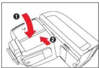
Notes:
• Always replace all of the batteries at the same time. - All four units should be of high quality and the same type.
BATTERY DISPOSAL
Used batteries do not belong in domestic garbage! Help to protect the environment and take used batteries to the appropriate collection points.
Please return only discharged batteries. They are usually discharged if the device that they operate no longer works perfectly when the batteries have been in prolonged use.
To protect against short circuits, the battery poles should be covered with a strip of adhesive tape.
Germany: As a consumer you are legally required to dispose of batteries in accordance with the return system. You can return batteries free of charge anywhere where you can buy them. As well as at public collection points in your town or municipality.
You will find these symbols on batteries containing harmful substances:
Pb= Battery contains Lead
Cd = Battery contains Cadmium
Hg= Battery contains Mercury
Li = Battery contains Lithium
ATTACHING/REMOVING THE FLASH UNIT
The description below applies equally, except for switching the camera off, to attaching to a camera or the pedestal supplied.
Attaching
- Turn off the camera and flash unit
- Push the flash unit foot as far as it will go into the camera's accessory shoe
- The locking pin (5b) must audibly engage.
In the case of accessory shoes without locking hole, the spring-loaded locking pin remains in the flash unit's foot so that the surface is not damaged.
Removing
- Turn off the camera and flash unit
- Press the release button (5a) and pull the flash unit out of the camera's accessory shoe
OPERATION
SWITCHING ON AND OFF
Switching on
Press the ⏻ button 6
Displays when the flash unit is switched on
- The pilot LED lights up in red initially, when the flash is ready it turns green (after just a few seconds if there is sufficient battery capacity). • The Index LED 8a lights up in white
- If the camera is appropriately equipped, flash readiness is displayed in the viewfinder and/or on the monitor.
Note:
You can fire a test flash by pressing the pilot LED 7.
Switching off
Press the ⏻ button 6 for approx. 1 s
Auto power off
Around 2 minutes after the last flash shot or the last operation, the flash unit switches back to standby mode to protect the battery capacity in the A, TTL and M modes (see p. 39/39/41).
In the SD and SF modes (see p. 41), this is done after around 5 minutes.
- To indicate standby mode, the pilot LED 7 flashes in a 2-second rhythm.
To reactivate the flash unit:
Tap the camera shutter release or press any button on the flash unit
If the flash unit is not used for longer than 60 minutes, i.e. no button or dial is operated and no flash fired, it switches itself off completely to prevent the batteries from discharging.
Notes:
- To protect against the electronics overheating, the flash unit is automatically switched to standby mode for a few minutes after a series of more than approx. 20 - 30 flashes in quick succession with a high energy level. To display this, the pilot LED7 flashes in intervals of 1.5 s. The unit cannot be activated during this cooling time.
- If the flash unit is not to be used for a prolonged period, we recommended switching it off and removing the power sources.
ZOOM REFLECTOR
The flash unit has a zoom reflector with which its illuminating angle can be adjusted to lens focal lengths of 24 to 105mm. Depending on the flash unit mode, this is done only automatically in A and TTL, only manually in SD and SF, or either automatically or manually in M. There is also automatic adjustment when the focal length of zoom lenses is changed.
Manual adjustment
Press the ⏻ button 6 for approx. 3 s (infinity loop, 1x per focal length stage)
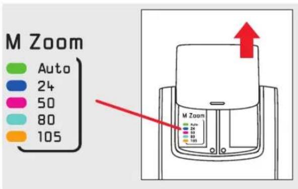
- To display the focal length set, the color of the pilot LED 7 changes (see next page)
Tip:
If you are using a zoom lens and do not always need the full range of the flash unit, it can be helpful to use the flash mode M that allows the shortest focal length of the lens to be set manually. This guarantees that the picture edges are always fully lit without you constantly having to adjust the lens focal length.
Example:
You are using a zoom lens with a focal length range of 24 to 90 mm. In this case, set the position of the reflector to 24 mm.
Notes:
- With automatic adjustment, as well as the settings outlined above, there are also settings for the focal lengths 28 mm, 35 mm, and 70 mm.
- Automatic adjustment of the zoom reflector presupposes camera models that transmit the focal length used to the flash unit. If this is not the case, the focal length must be set manually.
Please consult the relevant instructions for details on this subject.
- The focal length is not adjusted automatically if – the reflector head is pivoted
- the wide-angle diffusion screen is being used – the supplementary diffusion attachment is mounted
- All focal length details or settings in these instructions refer to the 35 mm format, i.e. 24 x 36 mm. When using cameras with smaller or larger formats, you have to compute the focal lengths applicable for optimum use of the flash range with the help of respective conversion factors.
Example:
Due to the APS-C format of the Leica T, the angle of view of its Summilux-TL 1.4/35 mm ASPH. corresponds to a focal length that is longer by a factor of approximately 1.5 - i.e., a 50 mm lens in a 35mm camera. Consequently, with the Summilux-TL 1.4/35 mm ASPH., you would have to set the zoom reflector to 50 mm. Please refer to the relevant instructions for the conversion factor valid for the camera used.
A list of the LED colors for the various focal lengths/automatic adjustment can be found on top of the reflector head if you pull the reflector card forwards.
With the integrated wide-angle diffusion screen (1c), lens focal lengths from 16mm can be illuminated.
Use
Pull the wide-angle diffusion screen out from the reflector head towards the front as far as it will go and let go. It then automatically folds up.
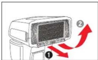
To push in, fold the wide-angle diffusion screen down by 90° and push in fully.
Notes:
- When the wide-angle diffusion screen is used, the zoom reflector is set in the position required for this (24 mm). It is not automatically adapted when the lens focal length is changed.
- Use of the wide-angle diffusion screen and the supplementary diffusion attachment (11, see pp. U1, 31 and 44) at the same time is not recommended.
Notes on range
- At close range or when using longer lenses and/or bigger/longer lens hoods, there may be shadows on the lower edge of the picture.
- Flash shots taken close to the subject may be overexposed. In such cases, indirect flash with the integrated reflector card (see p. 43), or with the slip-on diffusion attachment included (11, see pp. U1, 31 and 44) can help.
- Please note the guide number table (see Appendix) with respect to the maximum range to avoid underexposure.
FLASH MODES
You can choose between the following modes:
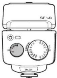
Video light (see p. 40)
SF Remote triggering without preflash (see p. 41)
SF Remote triggering with preflash (see p. 41)
M Manual operation (see p. 41)
A Fully automatic
TTL Fully automatic with the option to use flash exposure compensation
Setting procedure
Turn the selector dial 8 so that the desired mode is opposite the Index LED 8a.
A FULLY AUTOMATIC
Use this flash mode to achieve very good flash shots very simply. The camera controls the flash exposure. It measures the light reflected from the subject through the lens (TTL).
Depending on the camera, the camera fires an almost undetectable measuring preflash from the flash unit prior to the actual exposure.
All of the camera's exposure modes, i.e. programmed automatic (P), shutter priority (S/T), aperture priority (A) and manual setting (M) can be set.
TTL FULLY AUTOMATIC
As with A, however you can influence the flash illumination by entering a flash exposure compensation of -2 to +2 aperture values (EV) in half steps.
Reason:
Automatic flash exposure control is based on a reflectance of 25% (average reflectance of subjects). The subjects illuminated by the flash light may therefore in some cases be over or under exposed:
- the main subject is very dark or very bright/highly reflective - an (averagely bright) main subject is very small and/or in front of a very bright or heavily reflective background (e.g. with backlit shots), or in front of a very dark background (e.g. with night shots)
- The status LED 9d lights up as an indication that flash exposure compensation can be set.
SETTING FLASH EXPOSURE COMPENSATION
Turn the setting dial 9 so that the desired compensation value is opposite the Index LED 9a .
If you want to have uncompensated flash exposures you have to reset the compensation value to ☐
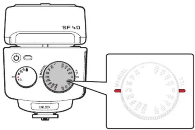
Tip:
- Dark subjects against a bright background: positive compensation value
- Bright subjects against a dark background: negative compensation value
Notes:
- The description above applies only to cameras that do not allow such settings themselves. With other cameras, the flash exposure compensation must be set on the camera. Read the camera's instructions for this. In the latter case, flash exposure compensation settings on the flash unit are ineffective.
- It is not possible to alter the flash exposure by changing the lens aperture since the camera's automatic exposure control treats the changed aperture as a normal working aperture again.
- When setting a compensation value, the flash range changes according to the following pattern: Positive compensation value = lower range Negative compensation value = higher range Also see the guide number table in the Appendix.
VIDEO LIGHT -
Ever more cameras are fitted with a video recording function. As an alternative to the flash function, this flash unit therefore offers an integrated video light 2.
- The status LED 9d lights up as an indication that the light brightness can be controlled.
Setting the light brightness
Turn the setting dial 9 so that the desired output level is opposite the Status LED 9a.
With Lithium batteries, the lighting time at maximum brightness (i.e. with setting at 1) is approx. 3.5 hours.
MANUAL FLASH OPERATION - M
In manual flash mode, flash output is always fixed at the level set. Possible ways of adjusting to the photographic situation include using the guide number calculation and aperture setting on the camera or by selecting an appropriate output level. The output levels range from full power to 1/256 (corresponds to 8 aperture steps).
- The status LED 9c lights up as an indication that the output level can be set.
Setting a partial light output stage
Turn the setting dial 9 so that the desired output stage is opposite the Status LED 9a. If you want to have full output again you have to reset the output value to 1
With these two modes the flash unit can be fired wirelessly through the flash burst of the main flash unit attached to or connected to the camera.
The two versions are designed to match the firing time to whether the main flash unit connected to the camera works with pre-flash - SD, or without it - SF. This ensures that this flash unit, i.e. the one not connected to the camera is only fired by the main flash burst.
Both versions correspond to M mode with respect to controlling the flash illumination, i.e. flash output is always fixed at the level set. Reduced output levels are set in the same way.
- The status LED 9c lights up in white as an indication that the flash output can be set.
Use
- Insert the flash unit in the pedestal supplied. If necessary, attach the pedestal to a tripod with its tripod thread.
- Align the main body of the flash unit with its sensor 3 towards the main flash unit and align the reflector head 1 as desired.
- On the camera set one of the two exposure modes A (aperture priority) or M (manual control), and the desired aperture, or in M also the desired shutter speed.
Possible ways of adjusting to the photographic situation include using the guide number calculation and aperture setting on the camera or by selecting an appropriate output level.
Notes:
- Set SD on the flash unit and fire a test flash from the main flash unit to ascertain whether it works with or without preflash. If the flash unit does not fire, change to SF.
- In most cases, several test shots with different positions of the flash unit, alignments of the reflector head and settings of the devices are needed to achieve the desired illumination. However, in very bright ambient light it may nevertheless be impossible to achieve appropriate flash illumination.
- The AF preflash function on the camera must be switched off.
- The zoom reflector is automatically set to 24 mm, but you can also select one of the other focal lengths (see p. 36).
- If several flash units of this type are to be used remotely from the camera, they must all be set to the same mode.
Important:
Do not mount the flash unit on metal accessory shoes that may cause a short circuit and thus damage it.
SYNCHRONIZATION
The flash synchronization speed (fastest possible shutter speed for flash shots) is automatically set for the camera's exposure modes, i.e. programmed automatic (P), shutter priority (S/T), aperture priority (A) and manual setting (M). With S/T and M you can also use slower shutter speeds.
Furthermore, in the A, TTL and M modes of the flash unit, flash operation with faster shutter speeds is also possible with cameras with the appropriate specifications (HSS).
Other flash-related functions possibly set on the camera, such as slow speed synchronization, synchronization to the end of the exposure and preflashes against the red-eye effect, are also possible.
Please refer to the instructions of the camera used for details on these camera functions.
FURTHER SETTINGS/FUNCTIONS
INDIRECT FLASH
With indirect flash, the subject is illuminated more softly and marked shadow formation is reduced. In addition, the physical decrease in brightness from the foreground to the background is reduced.
For indirect flash, the reflector head 1 of the flash unit can be pivoted horizontally and vertically.
Horizontal: in both directions in engaging 30° steps to max. 180°
Vertical: up in engaging 15° steps from 45° to 90°
Notes:
- To avoid color cast, the reflective surface should be neutral in color or white.
- When pivoting the reflector, make sure that it is pivoted by at least 60° if no direct light is to fall from the reflector onto the subject.
When the reflector head is pivoted, the zoom reflector is moved to the 70 mm position in modes with automatic adjustment (see p. 36) for this reason.
Indirect flash with the reflector card
With indirect flash with the integrated reflector card 1b slight brightening with a very soft shading effect can be achieved. The very small proportion of light directed to the front has other advantages: It generates highlights in eyes, reduces or even prevents the "red-eye" effect and allows flash shots without dazzle from shorter distances.
Removing/inserting reflector card
Pull out the reflector card to the front as far as it will go, i.e. until it engages in this position.
To insert, it just needs to be pushed back slightly from its engaged working position.
It then automatically returns to its initial position.
Use
Pivot the reflector head up by 90°.
Notes:
- Note the much smaller flash range. It is recommended to test the illumination in advance with test shots.
- The integrated wide-angle diffusion screen can not be used at the same time, i.e. it must be in its initial position.
SLIP-ON DIFFUSION ATTACHMENT
The slip-on diffusion attachment in the delivery scope 11 creates a much wider and softer distribution of the light emitted. You can use this for shots of subjects from a short distance, for example, or to avoid hard shadows.
Attaching/removing
- Align the slip-on diffusion attachment parallel to the reflector head 1 and with its slanting back parallel to the front of the reflector head, and push on as far as it will go
To remove, hold on both sides and pull off.
Note:
The slip-on diffusion attachment can be used together with the reflector card 1b.
Shot format
In some digital cameras, the flash unit can adapt the focal length display for the reflector position to the taking format (= sensor format).
This function presupposes cameras that transmit the focal length information to the flash unit.
AF AUXILIARY LAMP
The autofocus measuring systems of cameras depend on contrast on the subject. If the contrast is too low due to insufficient brightness, these cameras will switch on an AF auxiliary lamp.
When the flash unit is attached and with a camera with the appropriate specifications, the AF auxiliary lamp in the flash unit is activated. This projects a striped pattern onto the subject that the camera then uses for focusing.
The range is approx. 0.7 to 5 m (with 50 mm lens).
So that the AF auxiliary lamp can be activated by the camera, the autofocus mode "Single AF (S-AF)" must be set on the camera and the flash unit must indicate that it is ready to flash.
Some camera types only support the camera's internal AF auxiliary lamp. In such cases, the flash unit's AF auxiliary lamp is not activated (see camera instructions).
Notes:
- Slower lenses (largest aperture ≥ 5.6) sometimes greatly restrict the range of the AF auxiliary lamp.
- At short distances from the subject in conjunction with lenses of longer lengths, the AF auxiliary lamp may be switched off. In such cases, AF operation is not possible.
APPENDIX
MAINTENANCE AND CARE
The flash unit should be cleaned with a dry, soft cleaning cloth (e.g. microfiber cloth). If, however, there is more dirt, the screen surface can be cleaned with a very lightly moistened soft cloth.
Important:
Never use cleaning fluid. If cleaning liquid penetrates the screen frame, the components will be irreparably damaged.
FORMATION OF THE FLASH CAPACITOR
The flash capacitor in the flash unit undergoes a physical change if the unit is not switched on for a prolonged period. For this reason, it is necessary to switch the unit on for approx. 10 minutes every three months.
The power sources must supply enough energy to ensure that the flash ready light lights up 30 s after switching on at the latest.
TROUBLESHOOTING
If the flash unit does not work as expected, for example, switch it off for approx. 10 s using the main switch. Check the correct position of the flash unit foot in the camera's accessory shoe and the camera settings. Replace the batteries for new ones or freshly charged rechargeable batteries. The flash unit should work "normally" again after it is switched back on.
If this is not the case, please contact your specialist dealer. Below there are a few problems that can occur in practice with the flash. Possible causes or remedies for these problems are listed under each of the points.
The flash unit AF auxiliary light is not activated
- The flash unit is not ready to flash.
- The camera is not working in the "Single-AF (S-AF)" mode.
- The camera only supports its own internal AF auxiliary light. Various camera types support only the AF auxiliary light in the flash unit with the camera's central AF sensor.
If a non-central AF sensor is selected, the AF auxiliary light is not activated in the flash unit!
→ Activate central AF sensor!
The reflector's zoom position is not automatically adapted to the lens's current zoom position
- The camera is not transferring any data to the flash unit.
- There is no data exchange between the flash unit and camera. → Tap the camera shutter release button
- The camera is fitted with a lens without a data transfer interface.
- The reflector head has been pivoted out of its normal position.
- The wide-angle diffusion screen is folded in front of the reflector, or the slip-on diffusion attachment is being used.
The system does not switch automatically to the flash synchronization speed
- The camera or the lens used has central shutter (most compact cameras). → Switching to synchronization speed is not necessary.
- The flash unit works with high-speed synchronization (HSS). The system does not therefore switch to the synchronization speed.
- The camera works with shutter speeds that are slower than the flash synchronization speed.
Depending on the exposure mode of the camera, it does not switch to the flash synchronization speed (see camera instructions).
The shots are too dark
- The main subject is outside the range of the flash unit. Note: The range of the flash unit is reduced with indirect flash.
- The subject contains very bright or reflective picture sections. This means that the camera's measuring system is deceived. → Use flash mode TTL and set a positive flash exposure compensation, e.g. +1 EV
The shots are too bright
- The distance to the main subject is too short, or there is above-average brightness/strong reflection. → Use flash mode TTL and set a negative flash exposure compensation, e.g. -1 EV Or use the integrated reflector card / the slip-on diffusion attachment supplied.
SPARE PARTS ORDER NO.
| Slip-on diffusion attachment 422-310.003-006 |
| Pedestal 422-310.003-005 |
| Bag 439-600.243-000 |
TECHNICAL DATA
Guide number see table inside back cover
Flash modes A and TTL with automatic TTL flash exposure compensation, M, Sd, Sf with fixed flash output level, ■ for permanent light
Flash exposure compensation ±2 EV in 1/2 EV increments (with TTL), ■Video)
Manual output levels 1/1 - 1/256 (with M, Sd, Sf)
Flash duration 1/800 s with full energy (with M, Sd, Sf), 1/800 - 1/20000 s with automatic (with A, TTL)
Video light duration approx. 3.5 hours with fresh batteries and maximum brightness
Color temperature approx. 5600 K with full output ISO range ISO 50 to ISO 50000
Number of flashes/flash recycle time (min.-max., depending on battery type and flash mode) 220-1700/0.1-4 s
Illumination of the zoom reflector for 24/28/35/50/70/80/105 mm. Setting displayed by the color in which a LED is set, from 16 mm with integrated wide-angle diffusion head, depending on flash mode automatic or manual setting
Pivot ranges/engaging positions of the reflector head
Vertical: 45°, 60°, 75°, 90°
Horizontal in both directions: 30°, 60°, 90°, 120°, 150°, 180°
AF auxiliary lamp Automatic activation, working range approx. 0.7 - 5 m
Special functions: HSS flash with fast shutter speeds (with appropriately equipped cameras), high-speed flash synchronization; synchronization to the start or the end of the exposure, low-speed flash synchronization, reduction of red-eye effect (with appropriately equipped cameras, to be set there), wireless flash with firing by light pulse from lead flash unit for firing with or without preflash.
Power supply: Alkaline-Manganese batteries 1.5 V, type IEC LR6 (AA/Mignon), or Lithium batteries 1.5 V, type IEC FR6 (AA/Mignon), or Nickel-metal-hydride rechargeable batteries 1.2 V, type IEC HR6 (AA/Mignon), 4 pieces.
Power-saving system: After 2/5 min (depending on flash mode) automatically switches to stand-by mode, switch off after 60 min.
Dimensions (W x H x D): approx. 61 x 85 x 85 mm (reflector head to the front)/61 x 133 x 57 mm (reflector head up).
Weight (without power sources): approx. 200 g.
Delivery scope: Flash unit with slip-on diffusion attachment, pedestal, bag, instructions.
LEICA PRODUCT SUPPORT
The Product Support department at Leica Camera AG can answer any technical questions relating to Leica products, including support for the supplied software in writing, on the phone or by email. They are also the contact point for purchasing advice and to order instruction manuals.
Alternatively, you can send us your questions using the contact form on the Leica Camera AG homepage.
Leica Camera AG
Product Support / Software Support
Am Leitz-Park 5
D-35578 Wetzlar, Germany
Telephone: +49(0)6441-2080-111 /-108
Fax: +49 (0)6441-2080-490
info@leica-camera.com/software-support@leica-camera.com
LEICA CUSTOMER CARE
The Leica Camera AG Customer Care department or the repair service provided by authorized Leica agents in your country are available for service, maintenance and repairs of your Leica equipment (see the Guarantee Card for a list of addresses).
Leica Camera AG
Customer Care
Am Leitz-Park 5
D-35578 Wetzlar, Germany
Telephone: +49 (0)6441-189
Fax: +49 (0)6441-339
customer.care@leica-camera.com
FOREWORD
Dear customer,
Dear customer,
Attention
Notes
Video torch (see p. 64)
MANUAL FLASH MODE - M
Product Support / Software Support
Am Leitz-Park 5
D-35578 Wetzlar
Phone: +49(0)6441-2080-111 /-108
Fax: +49(0)6441-2080-490
info@leica-camera.com/software-support@leica-camera.com
LEICA CUSTOMER CARE
Note:
Note:
Product Support / Software Support
Am Leitz-Park 5
D-35578 Wetzlar
Phone: +49(0)6441-2080-111 /-108
Telefax: +49(0) 6441-2080-490
info@leica-camera.com/software-support@leica-camera.com
LEICA CUSTOMER CARE
Attention:
Warnings:
Product Support/Software Support
Am Leitz-Park 5
D-35578 Wetzlar
Telephone: +49(0)6441-2080-111 /-108
Fax: +49(0)6441-2080-490
info@leica-camera.com/software-support@leica-camera.com
LEICA CUSTOMER CARE
6 Main switch
Attention:
Note:
Product Support/Software Support
Am Leitz-Park 5
D-35578 Wetzlar

- ATTENTION
- NOTES
- LEICA CUSTOMER CARE
- MEANING OF DIFFERENT INSTRUCTION CATEGORIES
- NOTE
- IMPORTANT
- CAUTION
- COMPATIBLE CAMERAS
- TABLE OF CONTENTS
- CAMERA TYPE-DEPENDENT FUNCTIONS
- SAFETY NOTES
- CORRECT USE
- DISPOSAL OF ELECTRICAL AND ELECTRONIC EQUIPMENT
- DO NOT TOUCH SCA CONTACTS
- DESIGNATION OF PARTS
- PREPARATIONS
- POWER SUPPLY
- CHANGING THE POWER SOURCE
- PROCEDURE
- BATTERY DISPOSAL
- ATTACHING/REMOVING THE FLASH UNIT
- ATTACHING
- REMOVING
- OPERATION
- SWITCHING ON AND OFF
- SWITCHING ON
- DISPLAYS WHEN THE FLASH UNIT IS SWITCHED ON
- SWITCHING OFF
- AUTO POWER OFF
- TO REACTIVATE THE FLASH UNIT
- ZOOM REFLECTOR
- MANUAL ADJUSTMENT
- TIP
- EXAMPLE
- USE
- NOTES ON RANGE
- FLASH MODES
- SETTING PROCEDURE
- A FULLY AUTOMATIC
- TTL FULLY AUTOMATIC
- SETTING FLASH EXPOSURE COMPENSATION
- VIDEO LIGHT
- SETTING THE LIGHT BRIGHTNESS
- MANUAL FLASH OPERATION - M
- SETTING A PARTIAL LIGHT OUTPUT STAGE
- SYNCHRONIZATION
- FURTHER SETTINGS/FUNCTIONS
- INDIRECT FLASH
- INDIRECT FLASH WITH THE REFLECTOR CARD
- REMOVING/INSERTING REFLECTOR CARD
- SLIP-ON DIFFUSION ATTACHMENT
- ATTACHING/REMOVING
- SHOT FORMAT
- AF AUXILIARY LAMP
- APPENDIX
- MAINTENANCE AND CARE
- FORMATION OF THE FLASH CAPACITOR
- TROUBLESHOOTING
- THE FLASH UNIT AF AUXILIARY LIGHT IS NOT ACTIVATED
- THE REFLECTOR'S ZOOM POSITION IS NOT AUTOMATICALLY ADAPTED TO THE LENS'S CURRENT ZOOM POSITION
- THE SYSTEM DOES NOT SWITCH AUTOMATICALLY TO THE FLASH SYNCHRONIZATION SPEED
- THE SHOTS ARE TOO DARK
- THE SHOTS ARE TOO BRIGHT
- TECHNICAL DATA
- LEICA PRODUCT SUPPORT
- FOREWORD
- MANUAL FLASH MODE - M
- WARNINGS
Brand : LEICA
Model : SF 40
Category : Flash