
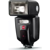
SF 60 - Flash LEICA - Free user manual and instructions
Find the device manual for free SF 60 LEICA in PDF.


| Product Type | System Flash Unit |
| Brand | Leica |
| Model | SF 60 |
| Dimensions (Horizontal) | Approx. 73 x 98 x 112 mm |
| Dimensions (Vertical) | Approx. 73 x 162 x 75 mm |
| Weight (without batteries) | Approx. 300 g |
| Power Supply | 4x AA alkaline (1.5V) or NiMH rechargeable (1.2V); optional external battery pack |
| Guide Number | See appendix in manual |
| Flash Modes | A (auto), TTL, M (manual), SD, SF (remote firing), ABC (remote control), Video Light |
| Flash Exposure Compensation | ±2 EV in 1/3 EV steps (TTL mode) |
| Manual Partial Output Levels | 1/1 to 1/256 in 1/3 EV steps |
| Zoom Reflector Coverage | 24-200 mm (automatic/manual); 16 mm with integrated wide-angle diffuser |
| Bounce Flash | Tilt: 45° to 90° in 15° steps; Swivel: 180° left/right in 30° steps |
| Video Light Output Levels | 9 levels |
| AF Assist Light Range | Approx. 0.7 - 5 m (with 50mm lens) |
| High-Speed Sync (HSS) | Yes (if camera supports) |
| Wireless Remote Control | 2.4 GHz, up to 100 m range (with optional Leica SF C1) |
| Keylock | Yes |
| Safety Features | Overheating protection, auto power off, battery polarity protection |
| Maintenance | Clean with dry soft cloth; switch on every 3 months for 10 min |
| Scope of Delivery | Flash unit, diffuser (clip-on), off-camera stand, carry bag, quick start guide |
| Repairability | No user-serviceable parts; contact Leica Customer Care |
Frequently Asked Questions - SF 60 LEICA
User questions about SF 60 LEICA
0 question about this device. Answer the ones you know or ask your own.
Ask a new question about this device
Download the instructions for your Flash in PDF format for free! Find your manual SF 60 - LEICA and take your electronic device back in hand. On this page are published all the documents necessary for the use of your device. SF 60 by LEICA.
USER MANUAL SF 60 LEICA
We wish you a great deal of fun and success taking photographs with your new Leica system flash unit. The best system flash solution for your Leica camera. Please read this manual to familiarize yourself with the full scope of functions your flash unit has to offer.
Please read the chapters "Safety Remarks" and "Important Information" before using the product for the first time. Knowledge of the content will prevent inadvertent damage to the product, possible injuries and other risks.
SCOPE OF DELIVERY
The standard scope of delivery* contains the following:
- Flash unit
- Diffuser (clip-on)
- Off-camera stand
- Carry bag
- Quick Start Guide
*The actual scope of delivery may vary depending on model.
LEGAL INFORMATION
REGULATORY INFORMATION
You will find the manufacturing date of your Leica SF 60 on the labels provided in the Warranty Card and/or on the packaging.
CE mark
The CE mark on our products documents compliance with the fundamental requirements of applicable EU guidelines.
Correct exposure values were assessed as part of EMC testing for CE marking.
DISPOSAL OF ELECTRICAL AND ELECTRONIC EQUIPMENT
(Applies within the EU and for other European countries with active waste separation policies.)
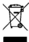
This device contains electric and/or electronic components which must not be disposed of in general household waste. Instead, it should be disposed of at a recycling collection point provided by your local authority.
This service is free of charge. Any standard or rechargeable batteries used in this device must be removed and disposed of separately in accordance with local regulations.
Please contact your local authorities, waste disposal collection point or the retailer, from whom you purchased the device for more information on correct waste disposal.
BATTERY DISPOSAL
Never dispose of depleted batteries in household waste! Do your part for the environment and take your depleted batteries to a collection point.
Only dispose of batteries once they are completely spent.
Cover the battery poles with adhesive tape to prevent a short circuit.
The following abbreviations can be found on the label of batteries containing hazardous materials:
| Pb Battery contains lead |
| Cd Battery contains cadmium |
| Hg Battery contains mercury |
| Li Battery contains lithium |
SAFETY REMARKS
WARNING
Non-compliance with the following points may result in serious injury or death.
- This flash unit is designed and certified for lighting subjects for photography purposes only. The device must not be used for any other purpose.
- It must only be used with the accessories described in this manual, or with accessories otherwise approved by Leica Camera AG.
- The flash unit must not be fired in close proximity to flammable gases or liquids (benzene, solvents, etc.)! Non-compliance may result in an explosion or fire.
- Avoid flash photography too close to the subject's eyes. The extreme light output can cause retinal damage in humans and animals, resulting in permanently impaired vision or even blindness.
- Never use flash photography in the direction of oncoming traffic of any kind, as drivers can be momentarily distracted, which can cause accidents. Before taking shots of moving traffic, switch the flash off or otherwise make sure that the flash will not be triggered.
- Do not touch the diffuser after repeated flash firing, as it can become very hot. Failure to observe this can result in burns!
- Never touch the contacts in the mounting foot of the flash unit.
-
If the case of the device has been damaged and internal components are visible, take care not to touch them – high voltage hazard! This also applies if there is a risk that water or other liquids could have penetrated the device case, or any kind of metallic or flammable object.
-
In these cases, remove the batteries. Take great care when doing so.
- Even after battery removal, the high-voltage circuitry can still hold a sufficient charge to cause electric shock, burns or other injuries.
- The device must therefore continue to be kept safe from moisture (e.g. rain or splash water) and must not be handled with moist hands. Do not attempt to disassemble, repair, or modify the device! The device interior does not hold any components that could be repaired by a layman.
- Please only use the batteries specified and approved in this manual.
- Do not short-circuit batteries or expose them to excessive heat (e.g. direct sunshine or fire).
- Depleted batteries must never be thrown into a fire!
- Do not attempt to recharge single-use dry cell batteries (primary cells).
CAUTION
Non-compliance with the following points may result in personal injury or damage to the device.
- Protect your flash unit against excessive heat and humidity. Do not store the flash unit in the glove compartment of your vehicle.
- Rapid changes in ambient temperature can result in condensation. Allow the flash unit time to acclimatize before using!
- Make sure that no opaque objects are positioned directly in front of the diffuser or directly on it when the flash is triggered. The diffuser must be clean. Failure to observe this can result in burn damage to the objects or the diffuser due to the extremely high energy output of the flash.
- The flash unit must only be used together with a camera-integrated flash if this can be fully opened out or extended.
- Do not use batteries that are damaged in any way!
- Depleted batteries can leak battery acid, which could damage the contacts. Always remove batteries from the device when not in use.
- The SCA contacts must not be touched directly. In some cases, touching the SCA contacts can result in damage to the device.
IMPORTANT INFORMATION
COMPATIBLE CAMERAS
The Leica SF 60 was designed for Leica cameras with autonomous flash exposure control, which use TTL (Through-The-Lens) metering like the Leica digital cameras of the S, SL, M, CL, and Q series. The Leica SF 60 can also be used with any other Leica camera model, but only in manual mode.
Using the Leica SF 60 with other camera brands is not recommended. Similarly positioned contacts with differing electric values in the accessory shoes of other camera makes may result in incompatibility, which may negatively impact the function of one – or both – devices. Leica Camera AG therefore does not extend its liability to damages based on using the flash unit with other camera brands and specifically to damages incurred beyond the actual flash unit.
Notes
- The descriptions in this manual are generally limited to the use of the Leica SF 60 in conjunction with Leica camera models from the current product range.
- This manual only describes the functions and settings of the Leica SF 60 flash unit itself. With very few exceptions, this also applies to displays and indicators.
It is therefore of utmost importance that you read the information about flash operation in the relevant camera manual regarding which flash functions are supported by the camera, flash-related camera settings, and the camera's own flash-related displays.
MODEL-DEPENDENT CAMERA FUNCTIONS
The flash functions listed below are available (depending on the equipment of the camera model used).
- Flash ready indicator in the viewfinder/on the LCD panel
- Automatic flash synchronization timer
- TTL flash mode
- Automatic fill-in flash mode
- Manual flash exposure compensation
- Start/end-of-exposure synchronization (camera setting)
- Automatic high speed synchronization, if supported by camera model
- Automatic zoom reflector control
- Pre-flash function to reduce red eye effect (camera setting)
- Cordless off-camera flash operation (remote settings and firing control)
- Continuous lighting for video recording
- Automatic power off functions
Note
- Data transfer is not available when using lenses/cameras without relevant bayonet interfaces. This will result in partial function limitations.
TABLE OF CONTENT
FOREWORD 2
SCOPE OF DELIVERY 2
LEGAL INFORMATION 3
REGULATORY INFORMATION ....3
SAFETY REMARKS 4
WARNING 4
CAUTION 5
IMPORTANT INFORMATION 6
COMPATIBLE CAMERAS ....6
MODEL-DEPENDENT CAMERA FUNCTIONS ....7
TABLE OF CONTENT 8
PART DESIGNATIONS 10
PREPARATION 12
POWER SUPPLY 12
REPLACING THE BATTERIES 12
POWER SAVE MODE (STANDBY MODE) 13
EXTERNAL BATTERY PACK AS POWER SUPPLY 14
ATTACHING/DETACHING THE FLASH UNIT 14
OPERATION 16
SWITCHING THE CAMERA ON/OFF 16
DISPLAYS WITH ACTIVATED FLASH UNIT 16
ADJUSTING THE ILLUMINATION ANGLE 16
ZOOM REFLECTOR 16
WIDE-ANGLE DIFFUSER 18
FLASH MODES 20
AUTOMATIC CONTROL BY THE CAMERA 20
A 20
TTL 20
FLASH EXPOSURE COMPENSATION 21
Definition of the various categories of information found in this manual
Note
- Additional information
Important
- Failure to comply with instructions may result in damage to the camera, the accessories or the recordings
Attention
- Non-compliance may result in personal injury
PART DESIGNATIONS
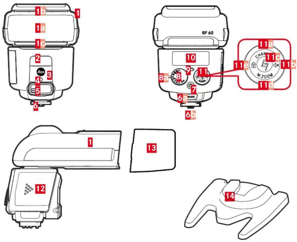
1 Reflector head
a Diffuser
b Bounce card
Wide-angle diffuser
2 Video light
3 Sensor for cordless off-camera operation (behind infrared-permeable panel)
4 AF assist light
5 Input jack for connecting external battery pack (behind cover)
6 Base
a Unlock button
b Locking pin
7 Main switch
8 Mode dial
a Index
9 Ready LED/test flash button
10 LCD panel
11 Setting ring/tilt selector with function information
a Channel selection
b Acoustic signal
Device pairing
d Zoom mode/focal length
Keylock
12 Battery compartment cover
13 Diffuser (clip-on)
14 Camera stand with 14 " thread
PREPARATION
POWER SUPPLY
This flash unit can be operated with the following power sources:
| 4 alkaline batteries, 1.5 V, IEC type LR6 (AA/mignon size) | 4 nickel-metal hydride (NiMH) rechargeable batteries, 1.2 V, IEC type HR6 (AA/mignon size) |
| This type of battery is maintenance-free and suitable for moderate power requirements. | This type of rechargeable battery has a significantly higher capacity than a nickel-cadmium (NiCd) rechargeable battery and is more environmentally friendly, as it contains no cadmium. |
Please read the technical information provided regarding the capacity of the various battery types (p. 34).
Attention
- Only use the power sources listed. Failure to observe this could damage the flash unit. That may in particular apply for specific types of lithium batteries (1.5 V, IEC type FR6, AA/mignon size), which may heat up excessively during use and cause burns, despite the automatic overheating protection of the device!
Important
- Always remove the batteries if you don't intend to use the flash unit for an extended period of time.
REPLACING THE BATTERIES
Batteries are depleted, when the recovery time between flashes increases to more than 30 s (recovery time = time after flash is fired at full output level (e.g. M) until the Ready LED lights up green again).
▶ Switch off the flash unit (see p. 16)
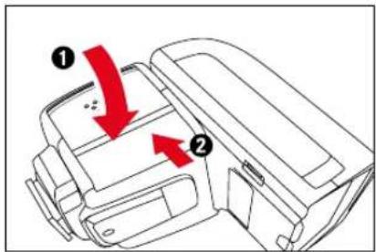
▶ Slide the battery compartment cover forward and release it
• The cover will automatically flip up.
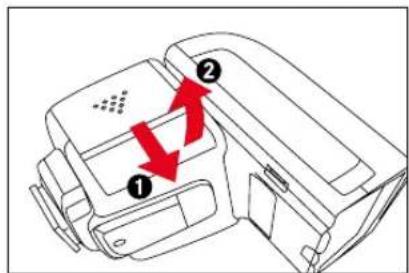
▶ Insert the batteries as shown in the diagram
- Ensure correct polarity.
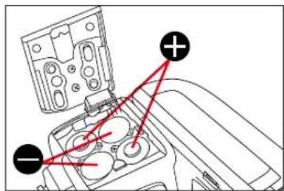
▶ Close the battery compartment by pressing down on the rear of the cover and then slide it back into place
Attention
- Incorrect battery polarity can destroy the flash unit!
- Improper battery use poses an explosion hazard!
Notes
• Always replace all batteries at the same time.
- All four batteries should be of high quality and must be of the same type.
POWER SAVE MODE (STANDBY MODE)
The flash unit will take the following actions to prolong battery life during times of inactivity:
| Inactivity Power saving measure | ||
| a few seconds Displays on the LCD panel are dimmed | ||
| a few minutes Standby mode (Ready LCD flashes green)depending on operating mode | ||
| 60 minutes Complete power off |
Reactivating the flash unit
Tap the camera shutter button
or
▶ Press the setting ring on any side
Notes
- The flash unit will automatically switch to standby mode after a series of around 20 to 30 quick-fire flashes at high output level to protect the electronic components of the device against overheating. The device cannot be reactivated during the cool-down phase and the Ready LED will flash in 1.5 s intervals during that time. The same will occur if the batteries are overheating.
- If you don't intend to use the flash unit for an extended period of time, we recommend switching it off and removing the batteries.
EXTERNAL BATTERY PACK AS POWER SUPPLY
The SF 60 has a port for connecting an external battery pack (e.g. by Nissin), for an increased maximum number of flashes and shortened flash recovery times. These accessories can be sourced from various manufactures and are available in specialist shops.
▶ Lift the rubber cover protecting the input jack
▶ Connect the battery pack via the supplied cable
Note
- The control functions of the SF 60 flash unit are powered exclusively by the internal batteries. That is why these batteries must still have enough power left to run these functions even if an external battery pack is used.
ATTACHING/DETACHING THE FLASH UNIT
The flash unit can be attached to a camera or to the base stand supplied. The stand attachment is the same as on the camera.
Notes
- Ensure that the camera is switched off while attaching the flash unit.
- On cameras with an accessory shoe that lacks the necessary hole for the locking pin, the spring-loaded pin fully retracts into the mounting foot of the flash unit and will not damage the surface of the accessory shoe.
ATTACHING
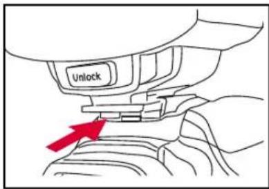
▶ Switch off the camera and flash unit (see p. 16)
- Push the mounting foot of the flash unit into the camera's accessory shoe
- The locking pin must audibly click into place.
DETACHING
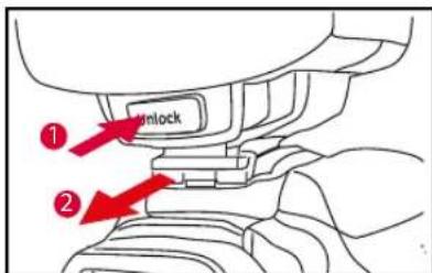
▶ Switch off the camera and flash unit (see p. 16)
▶ Press the unlock button
▶ Slide the flash unit out of the accessory shoe
OPERATION
SWITCHING THE CAMERA ON/OFF
▶ Press the Ⓧ button
DISPLAYS WITH ACTIVATED FLASH UNIT
- The Ready LED initially lights up red, and turns green as soon as the flash is ready (after a few seconds, provided the battery has sufficient charge).
- The symbols for the set flash mode appear on the LCD panel.
- In cameras that support this feature, the flash ready symbol will appear in the camera's viewfinder and/or LCD panel.
Note
- You can press the Ready LED for a test flash.
ADJUSTING THE ILLUMINATION ANGLE
ZOOM REFLECTOR
The flash unit is equipped with a zoom reflector that can adjust the flash coverage to the focal length of the lens in use between 24 and 200 mm. Depending on the selected flash mode, this will be automatic only (A), manual only (SD and SF), or optionally automatic or manual (TTL and M). Automatic adjustments continue on Vario lenses when zooming in or out.
▶ Press the setting ring at the bottom (foM.zoom) for about 1 s
- The current setting is shown on the LCD panel.
▶ Turn the setting ring to select the automatic setting or the focal length of your choice (in 9 increments from 24 mm to 200 mm)
▶ Press the setting ring again at the bottom for about 1 s
Tip
If you are using a zoom lens and know that you won't always be needing the full range of the flash, it can be helpful to set the flash unit manually to the shortest focal length of the lens. This will guarantee that the entire image area including edges will be fully illuminated without having to readjust the settings.
Example:
You decide to work with a zoom lens with a focal length range of 24 to 90 mm. In this case, set the position of the zoom reflector to 24 mm.
Notes
- The automatic focal length adjustment of the zoom reflector only works with camera models that transfer focal length information to the flash unit. If this is not the case, you will need to adjust the focal length setting manually. The manual of your camera model will tell you what information it will transfer to a connected flash unit of this type.
-
There will be no automatic focal length adjustment if:
-
the reflector head is turned to the left or right
- the wide-angle diffuser was removed
-
the clip-on softbox is attached
-
The last manual focal length setting will remain after the flash unit is switched off and on again.
- All focal length information or settings in this manual refer to the thumbnail format. When using cameras with smaller or larger formats, you will have to determine the correct focal length settings using the appropriate conversion factor for optimal use of the flash range.
- In some digital cameras, the flash unit can adjust the zoom display for the reflector position to the recording format (= sensor format). This function requires a camera that communicates focal length data to the flash unit.
WIDE-ANGLE DIFFUSER
The integrated wide-angle diffuser allows the use of lenses with focal lengths as short as 16 mm.
PULL OUT
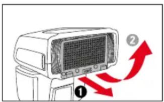
▶ Pull the wide-angle diffuser from the reflector head as far as it will go and release it
- The wide-angle diffuser will automatically flip up.
• _0 mm is displayed on the LCD panel.
PUSH IN
▶ Flip down the wide-angle diffuser by 90°
▶ Push it in fully
Notes
- The zoom reflector is moved to the required (24 mm) position when the wide-angle diffuser is in use. The illuminated focal length, however, will always be 16 mm, no matter which lens is used.
- The reflector will return to its previous setting when the wide-angle diffuser is flipped back.
- A concurrent use of the wide-angle diffuser and the clip-on diffuser is not recommended.
Notes on range
- The following may result in shadowing at the lower edge of the image:
- at close range
- when using larger lenses
-
when using larger lens hoods
-
Close range flash exposures may display overexposures. A use of the integrated bounce card (see p. 28) or the diffuser may be useful here.
- Please adhere to the values provided in the guide number table (attached) for max. range to prevent underexposure.
ENE
FLASH MODES
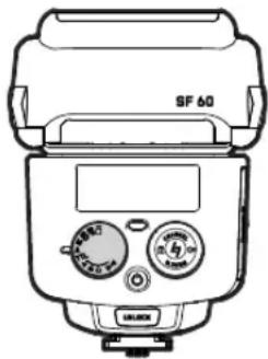
Select one of the following flash modes:
natural_image
Line drawing of a SF 60 air conditioner unit with control knobs and display (no text or symbols)| video light (see p. 26) | |
| SF | Remote firing without pre-flash (see p. 23) |
| SD | Remote firing with pre-flash (see p. 23) |
| M | Manual flash mode (see p. 22) |
| A | Automatic control by the camera(no flash exposure compensation available) |
| TTL | Automatic control by the camera(flash exposure compensation available) |
| ABC (11-11) | Wireless remote control (see p. 24) |
SETTING PROCESS
▶ Turn the mode dial until the desired mode is aligned with the index mark
- The relevant display appears on the LCD panel.
AUTOMATIC CONTROL BY THE CAMERA
A
This flash mode is the easiest way to achieve excellent flash photography results. Flash exposure metering is done by the camera. It measures the light reflected by the subject through the lens (TTL).
Depending on the camera model, the flash unit will produce a pre-flash for metering purposes just before the actual exposure.
Alle exposure modes of the camera are available.
TTL
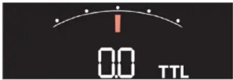
Automatic control by the camera as in mode A. In this mode, an additional flash exposure compensation of -2 to +2 EV in 1/3 EV increments can be set. This will allow an adjustment of the flash exposure.
Automatic flash exposure control systems are set to a light reflection factor of 25% (average reflection level of flash-lit subjects). Those part of the subject illuminated mainly by the flash may therefore be under or overexposed:
- the main subject is very dark or very reflective
- the main subject (of average brightness) is very small and/or in front of a bright or highly reflective background (e.g. backlighting), or in front of a very dark background (e.g. night time outdoors)
The LCD panel will show a light balance scale with EV digits underneath to indicate that flash exposure compensation is available.
FLASH EXPOSURE COMPENSATION
APPLYING FLASH UNIT SETTINGS
A flash exposure compensation value set on the flash unit will always be applied. A compensation value set on the camera may therefore be ignored.
▶ Turn the setting wheel until the desired compensation value is displayed on the LCD panel
- Dark subject in front of a bright background: positive exposure value (EV)
- Bright subject in front of a dark background: negative exposure value (EV)
APPLYING CAMERA SETTINGS
The flash unit must not have a flash exposure compensation value set if you want to set a compensation value on the camera.
▶ Turn the setting wheel to the exposure compensation value100.0
▶ Set the desired flash exposure compensation value on the camera
Notes
- Reset the flash exposure compensation value back to 0.00 for "raw" flash exposures.
- It is not possible to correct flash illumination by simply changing the lens aperture size, as the automatic exposure function of the camera will compensate with a higher or lower flash output.
- The flash exposure range changes as follows when a compensation value is set:
Positive exposure compensation value lesser range Negative exposure compensation value greater range
See also refer to the guide number table in the appendix.
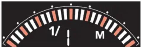
In manual flash mode, the flash unit will use the maximum flash output level unless separately adjusted. The flash intensity can be compensated by changing the lens aperture on the camera according to the guide number and/or by manually choosing a suitable partial light output setting. The partial light output settings range from maximum level to 1/256 (corresponding to 8 f-stops). A scale and a number display on the LCD panel allow the setting of the light output.
PARTIAL LIGHT OUTPUT SETTINGS
▶ Turn the setting wheel until the desired output level appears on the LCD panel
"UNFETTERED" FLASH
The Leica SF 60 can be attached to the camera or positioned as a standalone flash, e.g. for more complex lighting arrangements with any number of flash units.
Leica SF 60 flash units can be set up for standalone operation in one of two ways:
| Remote firing (SD and SF) | Remote control (ABC (⋯⋯)) (via Leica SF C1 remote control, optional accessory) |
| only manual presets of flash output on the flash unit | optionally TTL control or manual presets of flash output on the flash unit |
Notes
- The Leica SF 60 can also be used in a group with other flash units. Whether or not a flash unit is compatible with the Leica SF 60 for this purpose and what settings are required can be found in the relevant instruction manual of the flash unit concerned.
- A series of test exposures with various positionings and settings of the flash units will be required to get the desired lighting results. It may, however, be impossible to achieve the desired flash illumination in very bright ambient light.
• Max. range depends on the operating mode:
| ABC (0-1) | SD and SF |
| max. 100 m depending on the light intensity of the main flash unit; must be found by trial and error | |
POSITIONING AND DIRECTIONALITY
▶ Mount the flash unit on the camera stand
▶ Place in desired position
- The camera stand can optionally be mounted on a tripod via its tripod thread.
▶ Position the reflector head as required
Important
- Do not position the Leica SF 60 on metal mounts, as these could trigger a short-circuit and damage the device.
- Make sure to rotate the reflector head by 180^ if it is to point straight up, while the flash unit is mounted on the camera stand. This will improve the center of gravity relative to the camera stand and therefore its overall balance.
REMOTE FIRING - SD/SF
The Leica SF 60 can be fired wirelessly via another main flash unit attached to the camera or connected to the camera.
The two variants SD and SF align the firing function of the Leica SF 60 with whether or not the main flash works with a pre-flash. This ensures that the Leica SF 60 is only triggered for the main flash and not the pre-flash.
| SD | the main flash unit works with pre-flash |
| SF | the main flash unit works without pre-flash |
In terms of flash exposure control, both variants correspond to the M flash mode (see p. 22).
▶ Set the desired focal length for the zoom reflector (noF, see p. 16)
▶ Set the mode to SD
▶ Fire a test flash on the main flash unit, to see whether it uses pre-flash
- Should the Leica SF 60 fire as well:
Leave the settings as they are
- Should the Leica SF 60 not fire as well:
▶ Set the mode to SF
Notes
- All remotely set up Leica SF 60 flash units must be set to the same mode.
- The AF pre-flash function of the camera must be switched off.
REMOTE CONTROL - ABC (1-3)
You can operate any number of Leica SF 60 flash units from a distance of max. 100 m ^1 in this mode and in conjunction with the optional Leica SF C1 remote control. You can divide the flash units into up to three groups, and create universal settings for all flash units in a group independent of those for the other groups.
| Setting applies for all groups | Flash mode: M or TTL |
| Group-individual setting option available | Focal length and/or automatic operation of the zoom reflector (see p. 16) |
| Flash exposure compensation (for TTL) or output level selection (for M)(see p. 22) |
Note
- Please refer to the Leica SF C1 device manual for further details on how to operate the flash units via remote control.
PREPARATION
Before a Leica SF 60 can be used in this mode (receiver), it must first be “paired” with the Leica SF C1 (sender). Each device pair only needs to be paired once. The process ensures that the flash unit will only accept control signals from paired remote control units.
Please read the instruction manual of the Leica SF C1 for more details.
GROUP SELECTION
▶ Set the mode to A, B or C
- The Ready LED will flash at 2 s intervals to indicate readiness.
CHANNEL SELECTION
The remote control establishes a digital FR connection in the 2.4 GHz frequency band, which is subdivided into a large number of channels. In effect, multiple remote controls operating in the 2.4 GHz band on individual channels can be used to guarantee quick and fault-free communication between devices. It allows several photographers to use their SF 60/SF C1 equipment in the same environment without interference.
The channel settings for each remotely controlled flash unit must match the setting for the remote control that will be used for its operation. The SF 60 offers an automatic channel selection mode (R) or manual channel selection (1 - B) for that purpose:
▶ Press the setting dial at the top(Channel) for about 1 s
• Appears on the LCD panel.
▶ Turn the setting ring to the desired position
▶ Press the setting ring at the top for another 1 s
- The setting will be saved.
- The channel icon disappears from the LCD panel.
Notes
- Automatic channel selection (FAR) guarantees a successful pairing with the Leica SF C1, regardless of which channel is currently selected on that device.
- The automatic mode on th flash unit cannot be exited while a pairing is active.
- In order to guarantee successful pairing of the devices in manual mode, the same channels must be set for the flash unit and for the remote control. In case of an active pairing between the two devices, the channel setting of the Leica SF 60 can be changed at any time by the Leica SF C1. Channel 3 can, however, not be used for this purpose.
ACOUSTIC SIGNAL
Changes to existing settings transmitted by the remote control are acknowledged by the flash unit with an audible beep. The acoustic signal offers the security of knowing that the settings have been applied.
The signal can, however, also be muted.
Muting the acoustic signal
▶ Press the setting ring on the right(✗) for about 1 s
• appears on the LCD panel.
Unmuting the acoustic signal
▶ Press the setting ring on the right for about 1 s
• disappears from the LCD panel.
Note
- The mute/unmute setting can be changed on the Leica SF 60 directly or via the Leica SF C1. The acoustic signal is set to mute when the function is disabled on one of the two devices.
VIDEO LIGHT -
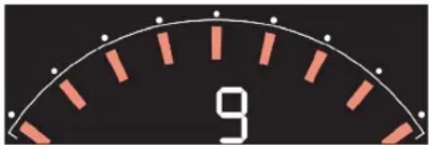
This flash unit offers an integrated video light for video recordings. A scale and a number display on the LCD panel allow the setting of the light output. 9 output levels are available.
SETTING THE LIGHT INTENSITY
▶ Turn the setting ring until the appropriate level of illumination is reached
- The light output level is displayed on the LCD panel.
ENE
OTHER FUNCTIONS
Note
- There are a range of additional functions that can be set on the camera, including long-term synchronization, end-of-exposure synchronization and pre-flash to remedy the 'red eye' effects. Please refer to the instruction manual of your camera model for details on these camera functions.
BOUNCE FLASH
An indirect or "bounced" flash creates a softer illumination of the object and prevents pronounced shadows. It also softens the contrast between the foreground and background lighting.
The reflector head of the flash unit can be swiveled (horizontally) and tilted (vertically) for a bounce flash.
| Horizontal Movement in 30° increments up to 180° in either direction |
| Vertical Movement in 15° increments from 45° to 90° |
Notes
- To avoid color casts in your photographs, you should always choose a white or neutral surface to bounce the flash off.
- When swiveling or tilting the reflector head, make sure to move it by at least 60^ to ensure that no direct light from the reflector falls on the object.
- In flash modes with automatic focal length adjustment (see p. 16), when the reflector head is swiveled for a bounce flash, the focal length of the zoom reflector is adjusted to 70mm for this purpose.
BOUNCE FLASH USING THE INTEGRATED BOUNCE CARD
Using the integrated bounce card can achieve a subtle lighting effect with very soft shadow lines The very small, forward directed portion of light has other advantages as well: It creates a specular highlight in your subject's eyes, reduces or entirely eliminates the 'red eye' effect and allows short-range flash photography without blinding.
REMOVING THE BOUNCE CARD
▶ Pull the bounce card forward AND out of its home position to the stop
- It will click into place in that position.
INSERTING THE BOUNCE CARD
▶ Push back on the bounce card slightly from its locked operating position
- The bounce card will then retract back into its home position automatically.
USE
▶ Tilt the reflector head upward by 90°
Notes
- The flash range is reduced considerably when the bounce card is in use. We recommend taking one or two test pictures to check the lighting.
- The integrated wide-angle diffuser cannot be used concurrently.
DIFFUSER (CLIP-ON)
The clip-on diffuser effects a much wider and softer distribution of the emitted light. A good option for recordings of very near objects or to avoid hard shadow lines.
ATTACHING
▶ Align the angled rear of the diffuser in parallel to the front of the reflector head
▶ Slide it on to the stop
DETACHING
▶ Hold it on the grooves on both sides and slide it off
Note
- The clip-on diffuser can be used concurrently with the bounce card.
- A concurrent use of the wide-angle diffuser and the clip-on diffuser is not recommended.
SYNC SPEED
The flash sync speed (fastest possible shutter speed for flash exposures) is set automatically by the camera. The S/T and M modes allow the use of slower shutter speeds.
Relevantly equipped camera models will also allow faster shutter speeds than the flash sync speed (HSS). The flash unit will then have to be set to A, TTL or M. The range for HSS flashes is significantly smaller than for TTL flashes.
AF ASSIST LIGHT
Autofocus metering systems in cameras rely on the contrast in the image object. These cameras will activate an AF assist light if there is insufficient contrast due to low light. The AF assist light integrated in the flash unit will be activated if the flash unit is attached to the camera and the camera offers the relevant setting.
The range is approx. 0.7 to 5 m (with a 50 mm lens).
Autofocus mode AFs must be enabled on the camera for it to activate the AF assist light directly.
Not all cameras support this function (refer to the relevant camera manual).
Notes
- Some low-light lenses (largest initial aperture ≥ 5.6 ) will limit the range of the AF assist light considerably.
- The AF assist light can be dimmed as needed for close-up photography with longer lenses.
KEYLOCK
All setting ring functions can be locked to prevent accidental changes.
LOCKING
▶ Press the setting ring on the left(☐) for about 1 s
• 🔒 appears on the LCD panel.
UNLOCKING
▶ Press the setting ring on the left for about 1 s
• disappears from the LCD panel.
ENE
CARE/MAINTENANCE
CARE
The flash unit should be cleaned with a dry, soft, and lint-free cloth (e.g. a microfiber cleaning cloth). The cloth can be moistened to remove stubborn dirt.
Important
- Never use liquid cleaning agents. The components inside the device could suffer irreparable damage if cleaning liquid penetrates the housing.
MAINTENANCE
The photoflash capacitor physically deteriorates if the flash unit remains switched off for prolonged periods of time. For this reason, the flash unit should be switched on at least once every three months for about 10 minutes.
The batteries used for this must be able to provide enough power to charge the capacitor to flash ready state as indicated by the LED within 30 s after switching on.
FAQ
In case of unexpected function:
▶ Switch off the flash unit
▶ Check that the mounting foot of the flash unit has been properly inserted into the accessory shoe of the camera and check the camera settings
▶ Replace the batteries as needed
▶ Switch on the flash unit
The flash unit should now function correctly, once it is switched back on. Please contact Leica Customer Care if that is not the case.
The following is a list of possible problems you may encounter when using the flash unit. Possible causes and remedies are listed for each one.
| Problem possible cause to be verified Troubleshooting suggestions | ||
| The focal length value of the zoom reflector is not automatically adjusted to the focal length of the lens. | No data is exchanged between the flash unit and the camera. Activate the camera (tap the shutter button) | |
| The lens used on the camera does not have the required data contacts for the lens mount. | ||
| The reflector head is not in its home position. | ||
| The wide-angle diffuser is flipped over the reflector. | ||
| The clip-on diffuser is attached. | ||
| The device does not automatically switch to flash sync speed. | The camera or the lens used has a central shutter (most compact cameras do). | A switchover to flash sync speed is unnecessary. |
| The flash unit is in high speed synchronization (HSS) mode. | ||
| The camera works with shutter speeds greater than the flash sync speed. Depending on the exposure mode chosen on the camera, no switch to flash sync speed will occur (see camera manual). | ||
| The exposures are too dark. | The main object is outside the range of the flash unit. | - Position the flash unit closer to the main object.- Avoid using bounce flash (it reduces the flash range).- Use TTL flash mode and set a positive flash exposure compensation, e.g. +1 EV |
| The object includes very bright or highly reflective image areas. This has confused the light metering system of the camera. | ||
| The exposures are too bright. You are too close to the main object, or it is excessively bright/highly reflective. | Use TTL flash mode and set a negative flash exposure compensation, e.g. -1 EV | |
| Insert bounce card/attach clip-on diffuser | ||
| The AF assist light of the flash unit is not activated. | The flash unit is not ready. | |
| The camera is not in AFs mode. | ||
| The camera only supports its own internal AF assist light. | ||
TECHNICAL DATA
Guide number
See appendix
Flash modes
- A and TTL with automatic TTL flash exposure control
- M for manual partial light output settings
- SD, SF for remote firing by flash pulse of master flash unit, with or without pre-flash, flash exposure control through manually preset partial light output settings
- ■ for constant light
- ABC(1-1) (requires Leica SF C1 controller, optional accessory), signal transmission in 2.4 GHz band, for remote firing and controlling
- the flash mode (either M or TTL)
- the partial light output settings (in M mode) or flash exposure compensation (in TTL mode)
Flash exposure compensation
±2 EV in 1/3 EV increments (in TTL mode)
Manual partial light output levels
1/1 - 1/256 in increments of 1/3 EV (M, SD, SF modes)
Manual video light output levels
9
Flash duration
in M, SD, SF modes: 1/800 s at full output
in A, TTL modes: 1/800 - 1/20 000 s at automatic output
Color temperature
About 5600 K at full output
Number of flashes/flash recovery time Weight (without batteries)
with device-internal power source; depending on battery type and flash mode: min. 220 - max. 1500/in. 0.1 s - max. 5.5 s
Video light duration
with device-internal power source with fresh batteries and at max. light output (= level 79): approx. 3.5 h
Light coverage/focal lengths of zoom reflector
for 24/28/35/50/70/85/105/135/200 mm
down to 16 mm with integrated wide-angle diffuser
in A flash mode: fully automatic setting only
Swivel and tilt settings/stop positions of reflector head
Vertical: 45^ , 60^ , 75^ , 90^
Horizontal, in both directions: 30^ , 60^ , 90^ , 120^ , 150^ , 180^
AF assist light
Automatic activation, working range approx. 0.7 - 5 m
Special functions
High speed synchronization (HSS) if supported by camera model, start-of-exposure and end-of-exposure synchronization, long exposure synchronization, reduction of red eye effects (if supported by camera model, camera setting)
Power supply
Alkaline batteries, 1.5 V, IEC type LR6 (AA/mignon size), nickel-metal hydride (NiMH) rechargeable batteries, 1.2 V, IEC type HR6 (AA/mignon size), 4 batteries in each case, external battery pack as additional power supply (optional accessory by different manufacturers)
Power save system
Flash unit automatically switches to standby after 2 or 5 min (depending on flash mode) and powers down after 60 min
Dimensions (W x H x D)
Reflector head in normal horizontal position: approx. 73 x 98 x 112 mm Reflector head in vertical position approx. 73 x 162 x 75 mm
Weight (without batteries)
approx. 300 g
Technical changes and errors excepted.
LEICA CUSTOMER CARE
Please contact the Customer Care department of Leica Camera AG for the maintenance of your Leica equipment and for help and advice regarding Leica products and how to order them. You can also contact the Customer Care department or the repair service provided by your regional Leica subsidiary for repairs or warranty claims.
Leica Camera AG
Leica Customer Care
Am Leitz-Park 5
35578 Wetzlar
Germany
Phone: +49 (0)6441 2080-189
Fax: +49 (0)6441 2080-339
Email: customer.care@leica-camera.com
www.leica-camera.com
LEICA ACADEMY
Have a look at our full seminar program with many interesting workshops on the topic of photography at: us.leica-camera.com/Leica-Akademie/Global-Leica-Akademie
ENE

DAS WESENTLICHE
Leica Camera AG | Am Leitz-Park 5 | 35578 WETZLAR | GERMANY
Telephone:+49 (0) 6441-2080-0 | Fax:+49 (0) 6441-2080-333 | www.leica-camera.com

- SCOPE OF DELIVERY
- LEGAL INFORMATION
- REGULATORY INFORMATION
- CE mark
- DISPOSAL OF ELECTRICAL AND ELECTRONIC EQUIPMENT
- BATTERY DISPOSAL
- SAFETY REMARKS
- WARNING
- CAUTION
- Non-compliance with the following points may result in personal injury or damage to the device.
- IMPORTANT INFORMATION
- COMPATIBLE CAMERAS
- Notes
- MODEL-DEPENDENT CAMERA FUNCTIONS
- Note
- TABLE OF CONTENT
- Definition of the various categories of information found in this manual
- Important
- Attention
- PART DESIGNATIONS
- PREPARATION
- POWER SUPPLY
- REPLACING THE BATTERIES
- POWER SAVE MODE (STANDBY MODE)
- Reactivating the flash unit
- EXTERNAL BATTERY PACK AS POWER SUPPLY
- ATTACHING/DETACHING THE FLASH UNIT
- ATTACHING
- DETACHING
- OPERATION
- SWITCHING THE CAMERA ON/OFF
- DISPLAYS WITH ACTIVATED FLASH UNIT
- ADJUSTING THE ILLUMINATION ANGLE
- ZOOM REFLECTOR
- Tip
- WIDE-ANGLE DIFFUSER
- PULL OUT
- PUSH IN
- Notes on range
- FLASH MODES
- SETTING PROCESS
- AUTOMATIC CONTROL BY THE CAMERA
- A
- TTL
- FLASH EXPOSURE COMPENSATION
- APPLYING FLASH UNIT SETTINGS
- APPLYING CAMERA SETTINGS
- PARTIAL LIGHT OUTPUT SETTINGS
- "UNFETTERED" FLASH
- POSITIONING AND DIRECTIONALITY
- REMOTE FIRING - SD/SF
- REMOTE CONTROL - ABC (1-3)
- GROUP SELECTION
- CHANNEL SELECTION
- ACOUSTIC SIGNAL
- VIDEO LIGHT -
- SETTING THE LIGHT INTENSITY
- OTHER FUNCTIONS
- BOUNCE FLASH
- BOUNCE FLASH USING THE INTEGRATED BOUNCE CARD
- REMOVING THE BOUNCE CARD
- INSERTING THE BOUNCE CARD
- USE
- DIFFUSER (CLIP-ON)
- SYNC SPEED
- AF ASSIST LIGHT
- KEYLOCK
- LOCKING
- UNLOCKING
- CARE/MAINTENANCE
- CARE
- MAINTENANCE
- FAQ
- TECHNICAL DATA
- Guide number
- Manual partial light output levels
- Manual video light output levels
- Flash duration
- Color temperature
- Number of flashes/flash recovery time Weight (without batteries)
- Video light duration
- Light coverage/focal lengths of zoom reflector
- Swivel and tilt settings/stop positions of reflector head
- Special functions
- Power save system
- Dimensions (W x H x D)
- Weight (without batteries)
- LEICA CUSTOMER CARE
- Leica Camera AG
- LEICA ACADEMY
Brand : LEICA
Model : SF 60
Category : Flash