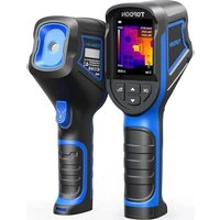
TC004 - Measuring equipment Topdon - Free user manual and instructions
Find the device manual for free TC004 Topdon in PDF.


User questions about TC004 Topdon
0 question about this device. Answer the ones you know or ask your own.
Ask a new question about this device
Download the instructions for your Measuring equipment in PDF format for free! Find your manual TC004 - Topdon and take your electronic device back in hand. On this page are published all the documents necessary for the use of your device. TC004 by Topdon.
USER MANUAL TC004 Topdon
Handheld Thermal Imaging Camera | User Manual
TOPDON
text_image
TOPDONContents
| EN | DE | FR | ES | IT PT RD | |||
| Cautions | 5 | 17 | 29 | 41 | 53 | 65 | 77 89 |
| About TC004 | 5 | 17 | 29 | 41 | 53 | 65 | 77 89 |
| Section 1What's in the Box? | 6 | 18 | 30 | 42 | 54 | 66 | 78 90 |
| Section 2Product Overview | 7 | 19 | 31 | 43 | 55 | 67 | 79 91 |
| Section 3 UsingTC004 in Standalone Mode | 10 | 22 | 34 | 46 | 58 | 70 | 82 94 |
| Section 4 UsingTC004 in USB Mode | 10 | 22 | 34 | 46 | 58 | 70 | 82 94 |
| Section 5Specifications | 12 | 24 | 36 | 48 | 60 | 72 | 84 96 |
| Section 6 FAQ | 13 | 25 | 37 | 49 | 61 | 73 | 85 97 |
| Section 7 Warranty | 14 | 26 | 38 | 50 | 62 | 74 | 86 98 |
English
Cautions
Read all instructions before use.
- Do not point the thermal imaging camera at the sun or other strong energy sources for long periods of time, otherwise there might be damage to the detector in the thermal imaging camera.
- Keep the thermal imaging camera away from water to avoid electricity leakage or short circuits.
- Do not touch the lens with your hands. Do not knock, pry, puncture, or scratch the lens.
- Do not disassemble the thermal imaging camera.
About TC004
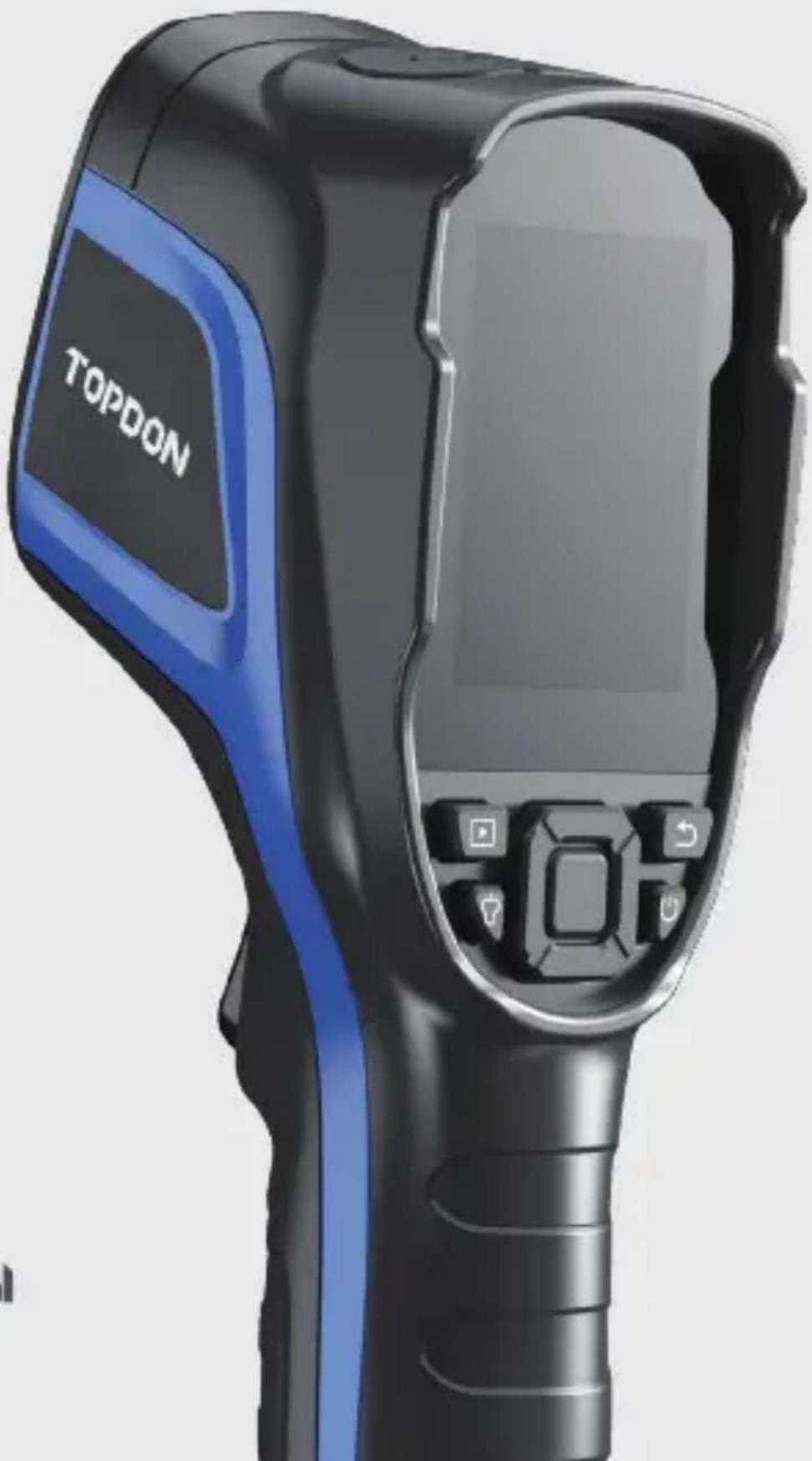
TOPDON's TC004 is a 256*192 handheld thermal imaging camera used for equipment inspection and maintenance.
You can apply the camera in home heating, water leak detection, and agricultural protection. It can be used either on its own in standalone mode or in USB mode to work with a Windows-based computer.
Section 1
What's in the Box?
natural_image
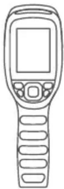
Line drawing of a handheld electronic device with control panel and display screen (no text or symbols)TC004 Thermal Imaging Camera

Power Adapter
natural_image
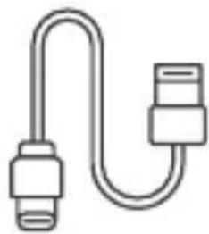
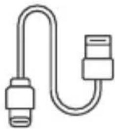
Simple line drawing of a U-shaped cable or connector with two connectors (no text or symbols)USB Cable (Type-A to Type-C)

text_image
USER MANUALUser Manual
Carrying Bag
Section 2
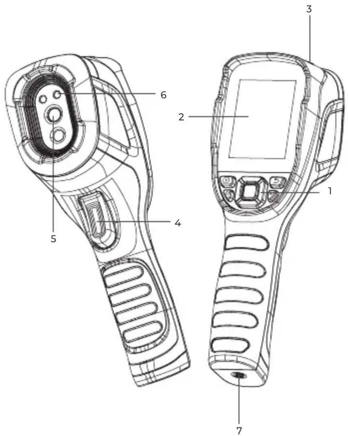
Product Overview
text_image
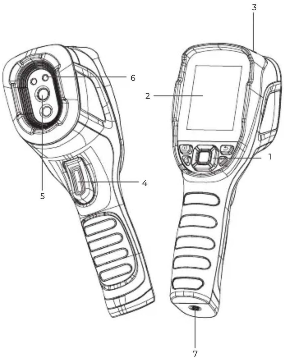
Technical diagram of a handheld device with numbered parts for identificationFigure 2.1.1
1. Keyboard
 | Power Button | Long press to power ON / OFF |
 | Return Button | Short press to return to the previous page |
 | Albums Button | Short press to view saved photos and videos |
 | Flashlight Button | Long press to turn on / off the flashlight |
 | Move Up / Down / Left / Right Buttons | Short press to move to the desired direction |
| OK Button | Short press to show the pop-out navigation menu; short press again to confirm an action or message |
2.2.8-Inch Screen
3. USB Type-C Port & SD Card Slot
Type-C port is used for charging, screen projecting to PC, and file transfer
4. Camera Button
Short press to take a photo, then short press the OK Button to save the photo; long press to start recording a video, short press to stop recording, then short press the OK Button to save the video.

Note: You can also choose to automatically save all the photos taken on your TC004 device. To enable the function, go to Setting > Photo Setting, and turn on Photo Auto Save.
-
Infrared Camera
-
Two LED Flashlights
-
Screw Hole (1 / 4-20 unc) Mounts the TC004 onto a tripod
Section 3
Using TC004 in Standalone Mode
While in standalone mode, the TC004 thermal imaging camera can work independently on its own. To learn more about the operation of each button and port on the TC004 device, you can refer to Section 2 Product Overview.
Section 4
Using TC004 in USB Mode
Apart from standalone use, your TC004 can also work with a Windows-based computer. This section illustrates how to configure your TC004 to work with a Windows-based computer for screen projecting and imagery analysis.
Getting Started
Download and install the TDView software
- Go to www.topdon.com/products/tc004, click "Download" to enter the download page. Then download and install the TDView software to your computer.
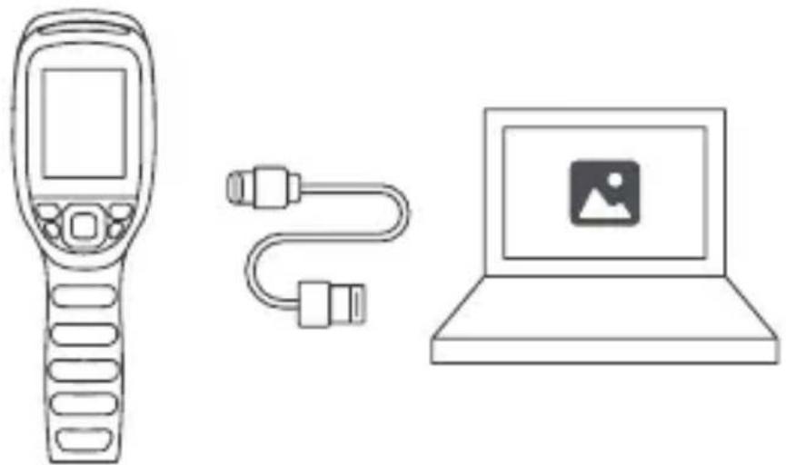
2. Connect TC004 to your computer with the supplied USB cable (see Figure 4.1.1).
natural_image
Line drawing of a remote control device, a cable with connectors, and a laptop displaying a profile icon (no text or symbols)Figure 4.1.1
- To project your TC004 screen to PC, you need to switch your TC004 to USB mode first (Go to Setting > System Setting, and tap Using Mode to switch to USB mode).
- Open the TDView software and you can screen project your TC004 thermal imaging camera to PC.
Imagery Analysis on PC
Once your TC004 is connected to PC via the supplied USB cable, you can send files (both JPG and IRC format files required) to the PC and conduct imagery analysis with the TDView software.

Note: Screen projecting and imagery analysis features cannot be available at the same time.
Section 5 Specifications
| Resolution of infrared camera | 256*192 |
| Spectral range | 8 to 14 μm |
| Pixel size | 12 μm |
| NETD | < 40 mK |
| FOV | 52.5°x 39.5° |
| IFOV | 3.85 mrad |
| Measurement range | -4° to 662°F (-20° to 350°C) |
| Measurement accuracy | ±2°C or ±2% of reading, the larger value shall prevail |
| Measurement resolution | 0.1°C |
| Storage capacity | 2 GB RAM + 16 GB internal storage |
| Battery capacity | 5,000 mAh |
Section 6
FAQ
Q Can the TC004 detect objects underwater, through glass or a wall?
A No. Infrared detectors mainly detects 8 to 14 m long-wave infrared areas, and can only be used to measure surface temperature.
Q Why is there a lower temperature reading when the device gets far from the object and a higher reading when the device gets closer to the object?
A Infrared radiation attenuates when passing through the atmosphere. The longer the distance, the greater the attenuation. Thus, the accuracy of temperature measurement at a distance will decrease. To ensure accuracy of measurement, go to Setting > Measure Parameter > Distance, and input the actual distance (max: 5 meters) to get the corrected temperature.
Q Why is the measured temperature not very precise?
A The temperature resolution of TC004 is ±2%. And the TC004 provides a normal temperature range of -4 to 302°F (-20 to 150°C), and a high temperature range of 302° to 662°F (150 to 350°C). Please select the corresponding range in the app before measuring.
Q What external factors will affect the infrared temperature measurement?
A The following factors will have an impact on the measurement results:
a) Emissivity of the object surface.
b) Ambient temperature: The object will reflect the infrared rays emitted by surrounding objects, which affects the temperature measurement of the object itself.
c) Atmospheric temperature: The atmosphere itself also emits infrared rays.
d) Atmospheric transmittance: the infrared rays emitted by the object are attenuated in the atmosphere.
e) Distance: the longer the distance, the greater the attenuation of the infrared rays emitted by the object in the atmosphere.
Section 7
Warranty
TOPDON's One Year Limited Warranty
TOPDON warrants to its original purchaser that the company's products will be free from defects in material and workmanship for 12 months from the date of purchase (Warranty Period).
For the defects reported during the Warranty Period, TOPDON will either repair or replace the defective part or product according to its technical support analysis and confirmation.
TOPDON shall not be liable for any incidental or consequential damages arising from the device's use, misuse, or mounting. If there is any conflict between the TOPDON warranty policy and local laws, the local laws shall prevail.
This limited warranty is void under the following conditions:
- Misused, disassembled, altered or repaired by unauthorized stores or technicians.
- Careless handling and / or improper operation.

Notice: All information in this manual is based on the latest information available at the time of publication and no warranty can be made for its accuracy or completeness. TOPDON reserves the right to make changes at any time without notice.
Section 8
FCC
This device complies with Part 15 of the FCC Rules. Its operation is subject to the following two conditions:
(1) this device may not cause harmful interference, and
(2) this device must accept any interference received, including interference that may cause undesired operation. "
Note: This equipment has been tested and found to comply with the limits for a Class B digital device, pursuant to Part 15 of the FCC Rules. These limits are designed to provide reasonable protection against harmful interference in a residential installation.
This equipment generates, uses, and can radiate radio frequency energy. If not installed and used in accordance with the instructions, it may cause harmful interference to radio communications.
However, there is no guarantee that the interference will not occur in a particular installation.
If this equipment does cause harmful interference to radio or television reception, which can be determined by turning the equipment on and off, the user is encouraged to try to correct the interference by one or more of the following measures:
- Reorient or relocate the antenna.
- Increase the distance between the equipment and receiver.
- Connect the equipment into an outlet on a circuit different from the one connected to the receiver.
- Consult a dealer or an experienced radio / TV technician for help.
Deutsch
Achtung
natural_image
Line drawing of a handheld electronic device with control panel and keypad (no text or symbols)TC004 Wärmebildkamera

Netzadapter
natural_image
Simple line drawing of a U-shaped cable or connector with two connectors (no text or symbols)text_image
USER MANUALtext_image
Technical diagram of a handheld device with numbered parts for identificationAbbildung 2.1.1
1. Tastatur
natural_image
Line drawing of a handheld electronic device with control panel and keypad (no text or symbols)natural_image
Simple line drawing of a U-shaped cable or connector with two connectors (no text or symbols)text_image
USER MANUALtext_image
Technical diagram of a handheld device with numbered parts for identificationFigure 2.1.1
1. Clavier
natural_image
Line drawing of a handheld device, a cable with connectors, and a laptop displaying a profile icon (no text or symbols)Figure 4.1.1
natural_image
Line drawing of a handheld electronic device with control panel and keypad (no text or symbols)natural_image
Simple line drawing of a U-shaped cable with two connectors (no text or symbols)Cable USB (Tipo A o Tipo C)

text_image
USER MANUALManual de Usuario

Mochila
Sección 2
text_image
Technical diagram of a handheld device with numbered parts for identificationFigura 2.1.1
1. Teclado
natural_image
Line drawing of a remote control device, a cable with connectors, and a laptop displaying a profile icon (no text or symbols)Figura 4.1.1
natural_image
Line drawing of a handheld electronic device with control panel and keypad (no text or symbols)natural_image
Simple line drawing of a U-shaped cable or connector with two connectors (no text or symbols)text_image
USER MANUAL
Borsa da trasporto
Sezione 2
text_image
Technical diagram of a handheld device with numbered parts for identificationFigura 2.1.1
natural_image
Line drawing of a remote control device, a cable with connectors, and a laptop displaying a profile icon (no text or symbols)Figura 4.1.1
natural_image
Line drawing of a handheld electronic device with control panel and keypad (no text or symbols)natural_image
Simple line drawing of a U-shaped cable or connector with two connectors (no text or symbols)text_image
USER MANUALtext_image
Technical diagram of a handheld device with numbered parts for identificationРисунок 2.1.1
1. Клавиатура
natural_image
Line drawing of a handheld electronic device with control panel and keypad (no text or symbols)natural_image
Simple line drawing of a U-shaped cable or connector with two connectors (no text or symbols)Cabo USB (Tipo A ou Tipo C)

text_image
USER MANUALManual do Usuário
Mochila
Seção 2
text_image
Technical diagram of a handheld device with numbered parts for identificationFigura 2.1.1
1. Teclado
natural_image
Line drawing of a remote control device, a cable with connectors, and a laptop displaying a profile icon (no text or symbols)Figura 4.1.1
natural_image
Line drawing of a handheld electronic device with control panel and keypad (no text or symbols)TC004 サーモイメージ ングカメラ

電源アダプタ

natural_image
Simple line drawing of a U-shaped cable or connector with two connectors (no text or symbols)USB ケーブル (A 型~ C 型)

text_image
USER MANUALユーザーマニュアル
手荷物
セクション2
製品概要
text_image
Technical diagram of a handheld device with numbered parts for identification图 2.1.1
1. キーボード
natural_image
Line drawing of a remote control device, a cable with connectors, and a laptop displaying a profile icon (no text or symbols)图4.1.1