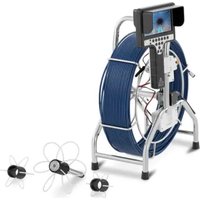
SBS-EC-600B3 - Video camera STEINBERG - Free user manual and instructions
Find the device manual for free SBS-EC-600B3 STEINBERG in PDF.


| Product type | Endoscopic camera |
| Brand | Steinberg |
| Model | SBS-EC-600B3 |
| Screen | 7-inch IPS |
| Video/photo resolution | 720x576 pixels |
| Camera sensor | CMOS |
| IP rating | IP68 |
| Cable length | 60 m |
| Cable diameter | 7 mm |
| Probe dimensions | Diameter 40 mm, length 117 mm |
| Viewing angle | 105° |
| Number of LEDs | 42 |
| Battery | Lithium-ion 4400 mAh, 12.6 V |
| Charger | Input AC 100-240 V ~ 50/60 Hz, output DC 12.5 V / 1000 mA |
| Charging time | 5 hours |
| Included memory | 8 GB SD card |
| Recording formats | Video AVI, photos JPG |
| Additional functions | Counter, digital zoom x8, audio, 512 Hz transmission, protective caps (100/140/220 mm) |
| Weight | 14.00 kg |
| Case dimensions | 440 x 170 x 590 mm |
| Included accessories | Charger, connector cable, key, screwdriver, seals, protective caps, sunshade |
| Power supply | Rechargeable battery or mains charger |
Frequently Asked Questions - SBS-EC-600B3 STEINBERG
User questions about SBS-EC-600B3 STEINBERG
0 question about this device. Answer the ones you know or ask your own.
Ask a new question about this device
Download the instructions for your Video camera in PDF format for free! Find your manual SBS-EC-600B3 - STEINBERG and take your electronic device back in hand. On this page are published all the documents necessary for the use of your device. SBS-EC-600B3 by STEINBERG.
USER MANUAL SBS-EC-600B3 STEINBERG
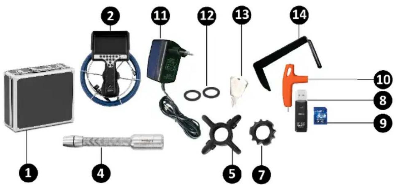
1 - Koffer
2 - Kontrollpult
3 – Suchkabel
4 - Sonde
5 – Schutzkappe
6 – Transporttrommel
LISTE DER BAUTEILE SBS-EC-300B
natural_image
Close-up of a gloved hand inserting a blue chip into a black handheld device (no visible text or symbols)AUFLADEN DER BATTERIEN
This manual is intended to assist you in safe and reliable use. The product is designed and manufactured strictly according to technical specifications using the latest technology and components, and maintaining the highest quality standards.
READ THE MANUAL CAREFULLY AND UNDERSTAND IT BEFORE USE.
To ensure long and reliable operation of the product, operate and maintain it correctly and strictly in compliance with this manual. The technical data and specifications in this manual are up-to-date. The manufacturer reserves the right to modifications for the purpose of quality improvement. Considering the technological progress and the feasibility of noise reduction, the product is designed and built so that risks resulting from noise emissions are minimised as far as possible.
Explanation of symbols
| CE | The product meets the requirements of relevant safety standards. | |
 | Read the manual before use. | |
 | Recyclable product. | |
 | CAUTION! or WARNING! or REMEMBER! indicates a specific instruction (general warning sign). | |
 | CAUTION! Risk of electric shock! | |
 | For indoor use only. | |

NOTE! The figures in this manual are illustrative only and may vary in some details from the actual appearance of the product.
The original version of the manual is in German language. Other language versions are translations from German.
2. Operating safety
CAUTION! Read all safety warnings and all instructions. Failure to follow the warnings and instructions may result in electric shock, fire and/or serious injury or death.
The term “appliance” or “product” in the warnings and instructions refers to the ENDOSCOPE CAMERA.
2.1. Electrical safety
a) The appliance power cord plug must fit into the mains outlet. Do not modify the plug in any way. Original power cord plugs and matching mains outlets reduce the risk of electric shock.
b) Avoid touching earthed objects, like piping, radiators, heaters, and refrigerators. There is an increased risk of electric shock if your body is earthed and touching the appliance exposed to direct rain, a wet floor or while operating in a humid environment. If water penetrates into the appliance, there is an increased risk of damage to the appliance and electric shock.
c) Do not touch the appliance with wet or moist hands.
d) Do not use the power cord in any unintended way. Never use it to carry the appliance or to unplug it from the mains outlet. Keep the power cord away from sources of heat, oil, sharp edges or moving parts. Damaged or tangled cords increase the risk of electric shock.
e) If you cannot avoid using the appliance in a wet environment, use a residual current device (RCD) to connect the appliance to electrical mains. Using an RCD reduces the risk of electric shock.
f) Do not use the appliance if the power cord is damaged or shows evidence of wear. Have a damaged power cord replaced by a qualified electrician or the manufacturer's technical service.
g) To avoid electric shock, do not immerse the power cable, its plug or the appliance itself in water or other liquid. Do not use the appliance on wet surfaces.
h) CAUTION – DANGER TO LIFE! When cleaning or using the appliance, never immerse it in water or other liquids.
2.2. Workplace safety
a) Do not use the appliance in areas of explosion hazard, for example in the presence of flammable liquids, gases or dust. The appliance generates sparks which can ignite dust or vapours.
b) In the event of damage or malfunction of the appliance, turn it off immediately and report the incident to authorised personnel.
c) If in doubt as to whether the appliance is working, contact the manufacturer's technical service.
d) Repairs to the appliance may only be carried out by the manufacturer's service. Do not attempt to repair the product on your own!
e) In the event of ignition or a fire, use dry powder or CO2 extinguishers only to suppress the fire of the appliance if live with electrical voltage.
f) Keep this manual for future reference. If the product is to be handed over to a third party, hand it over with this user manual.
g) Keep packaging components and small installation parts out of the reach of children.
h) Keep the appliance away from children and animals.
i) When operating this appliance together with other appliances, follow each of their user manuals.

Remember! Keep children and other bystanders safe while operating this product.
2.3. Personal safety
a) Do not operate the product if you are tired, ill or under the influence of alcohol, drugs or medication which might significantly impair your ability to operate the product.
b) The product is not intended to be used by individuals (including children) with reduced mental, sensory or intellectual capacity or lack of experience and/or knowledge, unless they are supervised by an individual responsible for their safety or have been given instructions by the responsible individual on how to operate the product.
c) The appliance is not a toy. Children must be supervised to ensure that they do not play with it.
2.4. Safe use of the product
a) Before adjustment, replacement of any accessories or storing the appliance, unplug it from the mains. This safety precaution reduces the risk of accidental operation.
b) Keep unused appliances out of the reach of children and anyone unfamiliar with the appliance or this manual. Appliances are dangerous in the hands of inexperienced users.
c) Keep the product in good working order. Before each use, check for generally evident damage and damage to any of the moving parts (inspect for cracks in parts and components or any other condition that may affect the safe operation of the product). If damaged, have the product repaired before use.
d) Keep the product out of the reach of children.
e) The product shall be repaired and maintained by qualified personnel using original spare parts only. This will ensure safe operation of the product.
f) To ensure the designed operational integrity of the product, do not remove the factory-installed covers or loosen any bolts.
g) Clean the appliance regularly to prevent permanent deposits of dirt.
h) The appliance is not a toy. Cleaning and maintenance shall not be performed by children without adult supervision.
i) Never attempt to tamper with the appliance to change its parameters or structure.
j) Keep the appliance away from sources of fire and heat.
k) Do not cover the vents of the appliance!
I) It is forbidden to pour liquids inside or on the appliance.
m) Do not use the appliance for medical purposes.
n) Protect the appliance from shocks, impacts, falls, etc.
o) Always remove batteries from the appliance before cleaning.
p) When replacing batteries, always use new batteries with the same parameters.
q) Do not bend the probe (camera cable) at an angle greater than 90^ .
r) Make sure that the product does not come into contact with live electrical parts.
s) Do not use the appliance if there is steam (moisture) inside the camera.
t) Do not remove the SD card when recording or playing as this may damage the system and/or the SD card.
u) Do not direct the light source at the eyes.
v) Do not place the battery pack together with metal objects that could short circuit the battery contacts.

CAUTION! Although the appliance has been designed to be safe and has been provided with adequate safeguards, and despite the use of additional safety measures, there is still a low, residual risk of accident or injury during its duration. Caution and common sense are advised when using the product.
3. Rules of use
The appliance is intended for inspection of hard-to-reach places (internal spaces of machines, engines, sewage pipes, etc.). The design used ensures proper lighting of supervised zones with the possibility of recording/exporting inspection images or videos.
The user is responsible for any damage caused by non-intended use.
3.1. Appliance overview
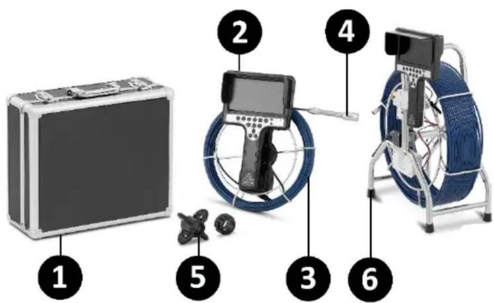
1 - Case
2 - Control panel
3 – Guide cable
4 - Probe
5 – Protective cap
6 – Transport drum
SBS-EC-300B PARTS LIST
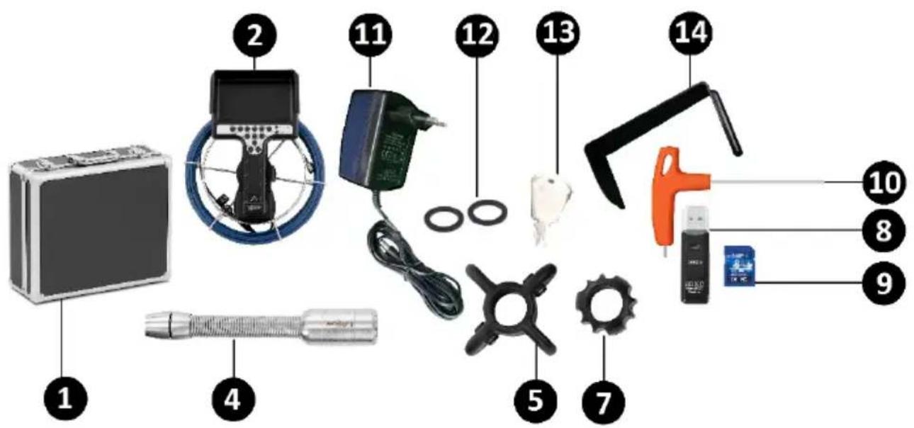
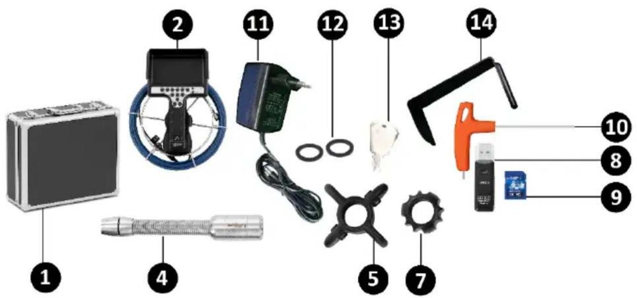
1 - Case
2 – Control panel with guide cable
4 - Probe
5 – Protective cap 80 mm
7 – Protective cap 40 mm
8 - USB port
9 – SD memory card
10 - Screwdriver
11 - Charger
12 - Gasket x2
13 - Key
14 – Guard
SBS-EC-300C PARTS LIST
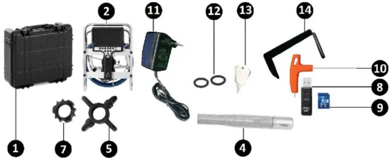
1 - Case
2 – Control panel with guide cable
4 - Probe
5 – Protective cap 80 mm
7 - Protective cap 40 mm
8 - USB port
9 – SD memory card
10 - Screwdriver
11 - Charger
12 - Gasket x2
13 - Key
14 – Guard
SBS-EC-600B4 PARTS LIST
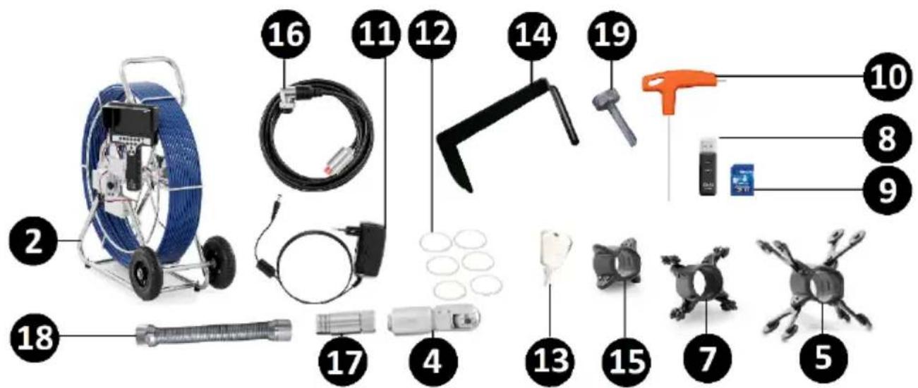
2 – Control panel with guide cable
4 - Probe
5 - Protective cap 220 mm
7 - Protective cap 150 mm
8 - USB port
9 - SD memory card
10 - Screwdriver
11 - Charger
12 - Gasket x6
13 - Key
14 - Guard
15 – Protective cap 110 mm
16 – Connection cable
17 – Transmitter 512 Hz
18 – Spring
19 - Screw x4
SBS-EC-600B3 PARTS LIST
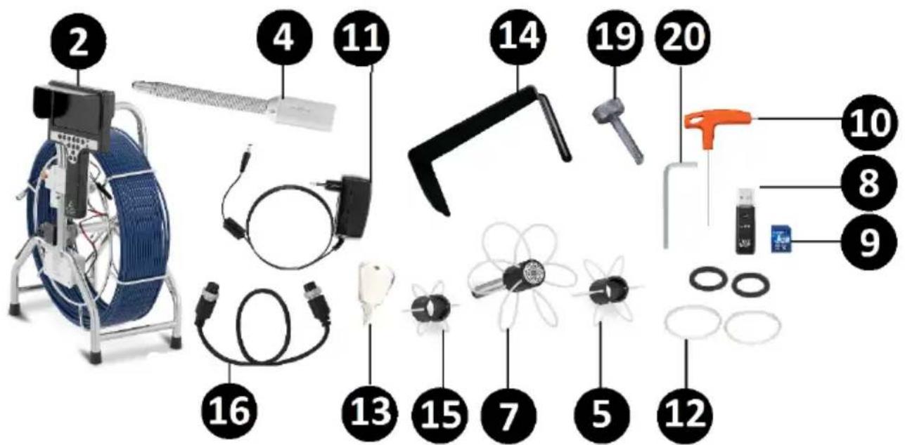
2 – Control panel with guide cable
4 - Probe
5 – Protective cap 140 mm
7 - Protective cap 220 mm
8 - USB port
9 – SD memory card
10 - Screwdriver
11 - Charger
12 - Gasket x4
13 - Key
14 – Guard
15 – Protective cap 100 mm
16 - Connection cable
19 - Screw x4
20 - Screwdriver
3.2. Preparations for operation
POSITIONING THE APPLIANCE
The operating temperature range of the appliance must not exceed -10^ to 35^ . The operating time of the equipment should be adjusted to the prevailing environmental conditions. The lower the temperature, the shorter the operating time.
Always operate the appliance on a level, firm, clean, fireproof, and dry surface and out of the reach of children and individuals with reduced mental, sensory and intellectual capacities. Position the appliance where the mains plug can be reached at any time. Make sure that the mains power ratings match the data on the rating plate!
3.3. Operating the appliance

CAUTION! Before installation/work on this appliance make sure that all components are complete and undamaged! Contact the supplier if any deviations are found!
3.3.1. CONTROL PANEL - INTRODUCTION
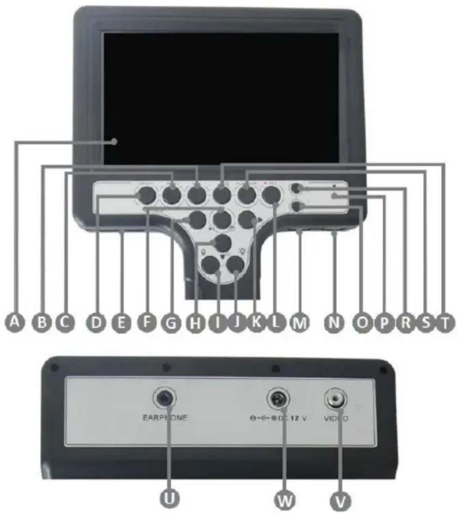
A - 7" display
B - "ESC" exit button
C - "MENU" button
D - "ON/OFF" power button
E - SD memory card input
F – “Confirm/Stop/Photo” button
Select and hold to enter the directory of saved images
G – Move to the left “◀” key
H – Image ZOOM - reduction button / move down “▼” directional key
I - Adjustment “-” of LED afterglow
J - Adjustment “+” of LED afterglow
K – Right directional button “▶”
L – “REC” button to start/stop recording
M – Keypad connection input
N – USB port connection input
O - Button for unit selection "M/Ft" (metric/imperial)
P - Microphone
R - Value reset button
S – Directory of "PLAY BACK" files
T – Image ZOOM + button / move down “▲” directional button
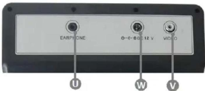
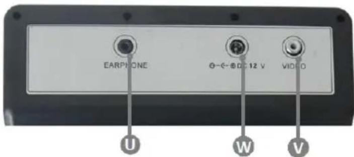
U – Headset connection input
W - Charger plug input
V – Video output
3.3.2. CONNECTION OF SBS-EC-300B / SBS-EC-300C
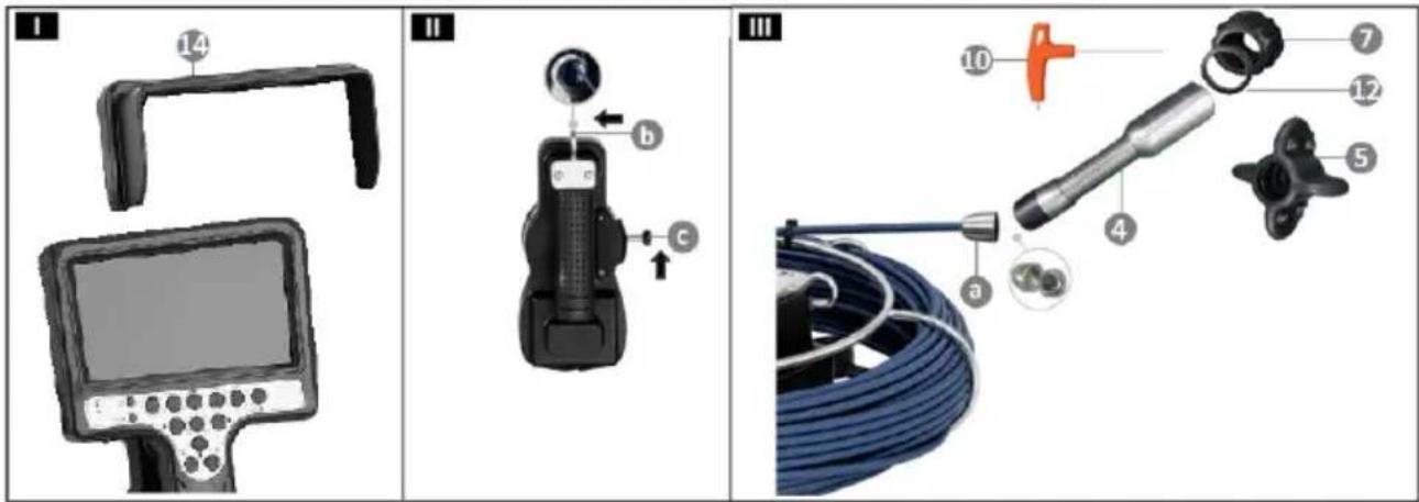
Before work install a sun visor by sliding it onto the control panel (I-14).
Release the guide cable spool lock (II-c) and guide the cable through the safety handle (II-b).
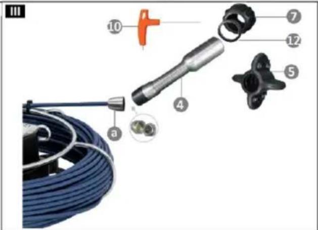
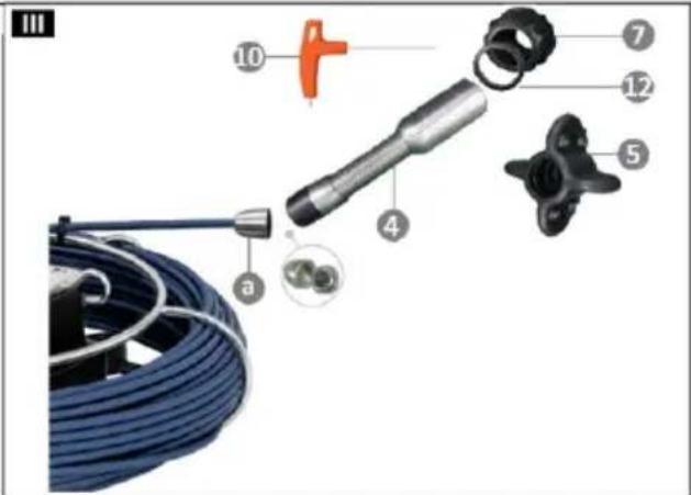
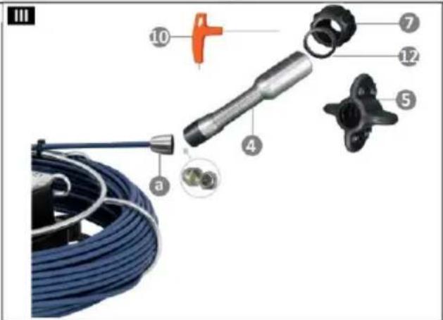
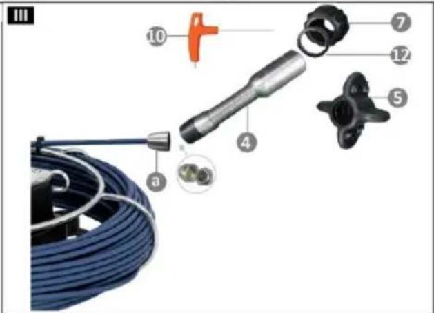
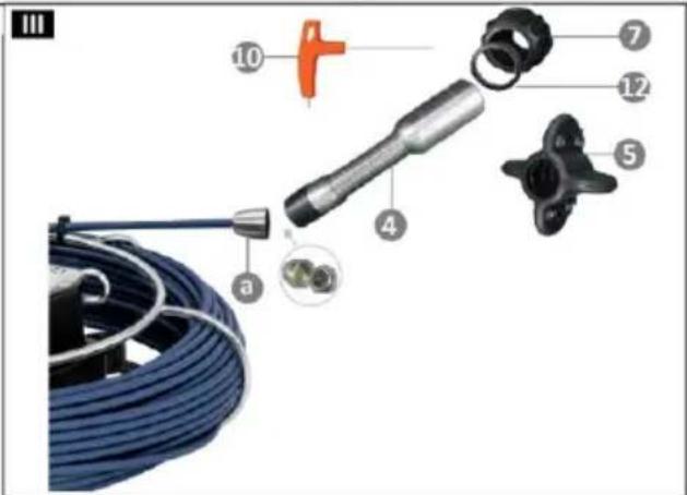
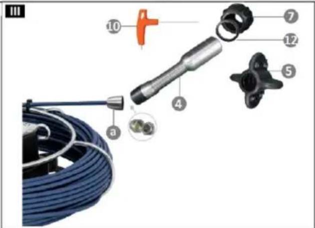
Slide the insulation gasket (III-12) onto the probe, then place the protective cap 40 mm (III-7) or 80 mm (III-5). Attach the structure by tightening the connection screws with a screwdriver (III-10).
Connect the probe to the camera head connection output (III-a).
Turn on the appliance by pressing and holding the power button (for about 3 s - 3.3.1. -D). The control LED will light up.
Adjust the light intensity of the probe LEDs using the afterglow adjustment buttons (3.3.1. - I/J).
3.3.3. CONNECTION OF SBS-EC-600B4 / SBS-EC-600B3
Before work install a sun visor by sliding it onto the control panel (I-14).
Attach the control panel to the frame. For this purpose use the fixing screws included in the set. Tighten the structures tightly (IV-19).
Connect the connection cable (16) to the power input of the control panel (V-d) and the power outlet of the guide cable panel (V-e). Switch to "C50" (V-j).
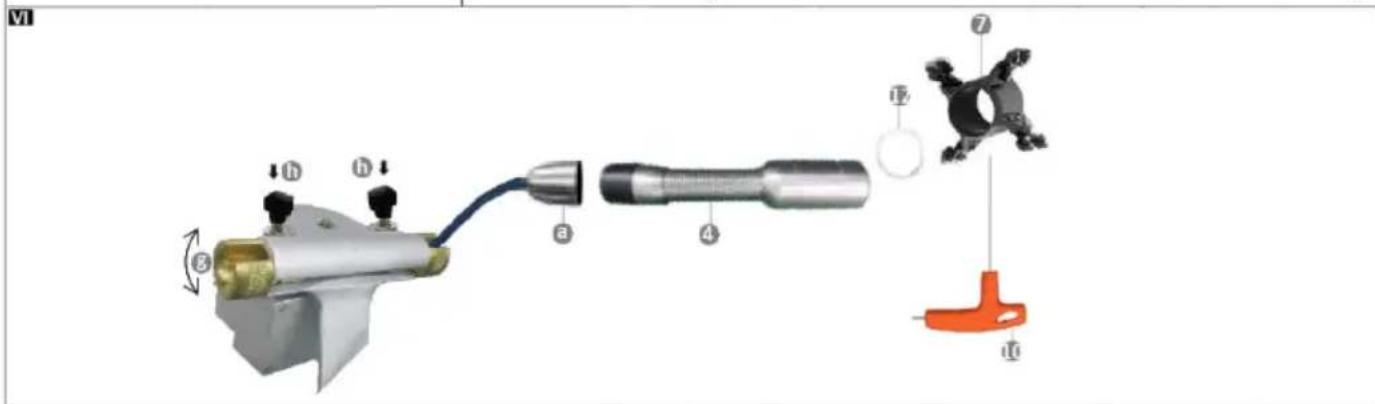
Slide the insulation gasket (VI-12) onto the probe (4), then place the protective cap adapted to individual needs (VI-7). Attach the structure with a screwdriver (VI-10) by tightening the connection screws.
Release the guide cable drum lock (V-k) and loosen the guide cable fixing knobs (VI-h). Position the clamping sleeves, so that the guide cable can be seated. Pass the guide cable through the clamping sleeves and lock by turning the sleeves. Attach the knobs fixing the guide cable (VI-h).
Connect the probe to the guide cable camera head connection output (VI-a).
If the design contains a transmitter 512 Hz and a connection spring, connect the probe (VI-4) with an attached protective cap with the transmitter 512 Hz by bolting them together. Attach the connection spring to the transmitter by
proceeding in a similar manner to the installation of the transmitter. Connect the structure to the guide cable camera head connection output.
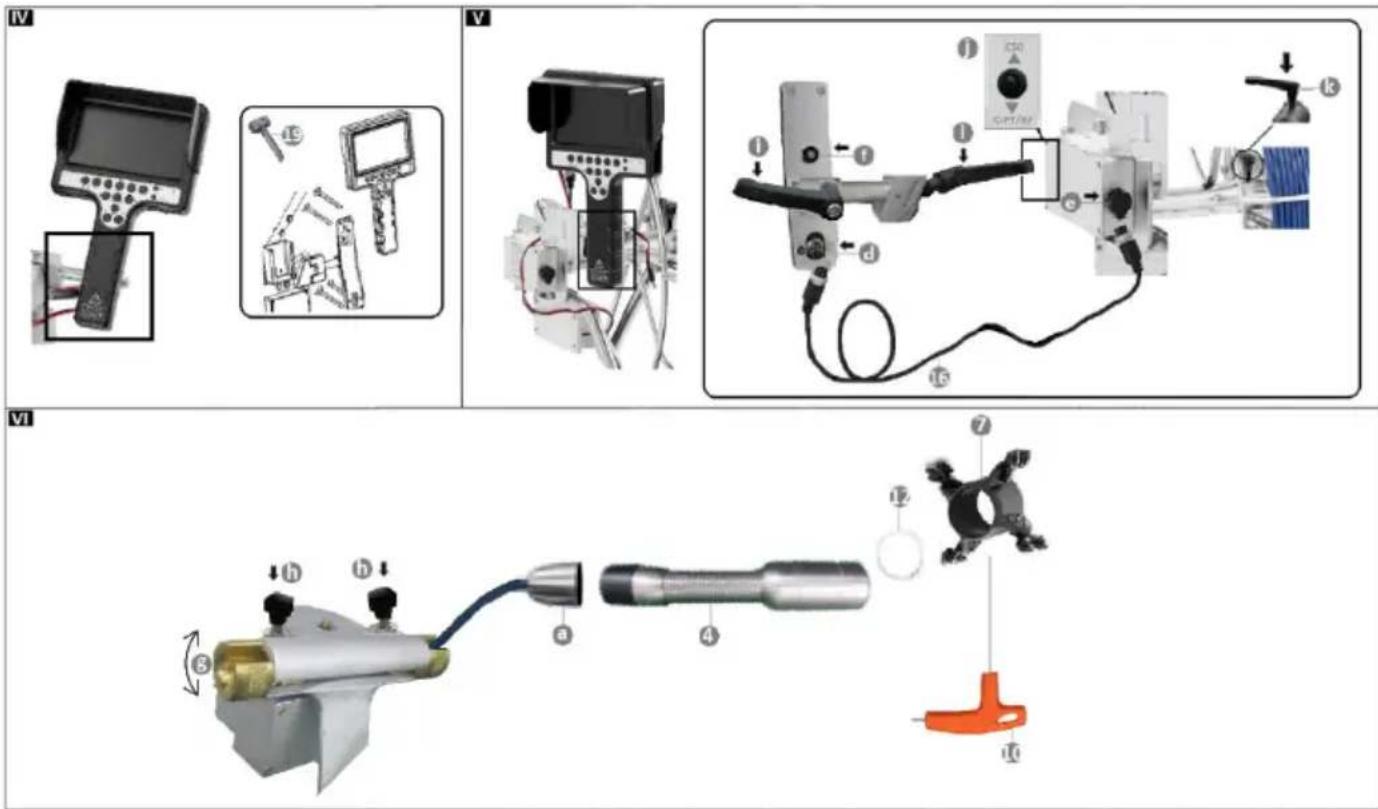
The frame adjustment knobs (V-i/j) allow the position of the monitor to be adapted to individual needs.
Turn on the appliance by pressing and holding the power button (for about 3 s - 3.3.1. -D). The control LED will light up.
Adjust the light intensity of the probe LEDs using the afterglow adjustment buttons (3.3.1. - I/J).
3.3.4. CONNECTING EQUIPMENT / CHARGING BATTERIES
SD MEMORY CARD INSTALLATION

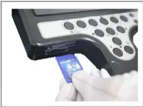
CAUTION! Pay attention to the correct positioning direction of the SDory card in the appliance!
Insert the dedicated SD memory card into the reader and press slightly. A properly installed card should slightly protrude and may be perceived with your finger. To remove the data carrier, carefully press the card, which will cause it to slide out. Remove the card.
natural_image
Close-up of a gloved hand inserting a blue chip into a black handheld device with circular buttons (no visible text or symbols)CHARGING BATTERIES
CAUTION! Use only batteries with the parameters given in the technical data table! Using improper battery type may damage the appliance!
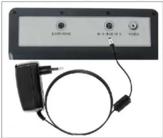
Connect the charger to the power socket. The control LED of the charger will light up in green.
Place the charger plug in the charging cable connection input located on the rear panel of the monitor. The control LED of the charger will light up in red.
The optimum battery charging time is 5 hours. When the battery charging process ends, the control LED of the charger will turn green.
CAUTION! Before starting work with the appliance, first connect the USB drive! If there is a problem with reading data, restart the system!
VIDEO RECORDING
Press the “REC” button (L). A camera symbol will appear on the screen. Pressing the on/off switch again will complete the recording of the video. During video recording it is possible to take photographs.
TAKING AN INSPECTION PHOTO
Press the "Confirm/Stop/Photo" button (F).
Press and hold the button (F) to enter the directory of saved images.
IMAGE ZOOM CONTROL
Press “▲” to enlarge the inspection area.
Press “▼” to reduce the inspection area.
PLAYING STORED VIDEOS/PHOTOS AND REMOVING FILES
Images and videos are stored in the appliance memory. In order to restore data, open the storage directory.
→ VIDEO DIRECTORY
To directly navigate to the video directory, press the "PLAY BACK" button (S). To play the stored video, press the "Confirm/Stop/Photo" button (F). To stop/resume the video, press the "Confirm/Stop/Photo" button again (F).
Use the directional buttons “◀”, “▶” to scroll the video forward or backward.
Press the "ESC" exit button (B) to return to the main menu.
→ IMAGE DIRECTORY
Press and hold (for approx. 3 s) the "Confirm/Stop/Photo" button (F).
Pressing the button again will display the desired photo. Use the directional buttons to:
display the previous image “◀”;
display the next image “▶”.
Press the "ESC" exit button (B) to return to the main menu.
→ DELETING FILES
To delete a stored file/folder, press the "MENU" button (C). Select the deleted item. Confirm by pressing the "Confirm/Stop/Photo" button (F). Press the "ESC" exit button to return to the main menu.
MENU
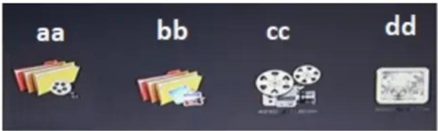
Pressing the “MENU” function button (C) allows for entering the directories of recorded videos (aa), images (bb), video settings (cc) and system settings (dd). To select the appropriate directory and change parameters, use the following function buttons: „◀”; „▲”; „▶”; „▼” and the “Confirm” button (F).
→ VIDEO SETTINGS
Enter the settings directory by pressing the "Confirm/Stop/Photo" button (F).
Change the settings according to own preferences:
• Recording time: 5/15/30 min;
• Video audio recording; ON/Off;
• Composite video baseband signal (CVBS): NTSC/PAL;
- Sound volume [for adjustment press the "Confirm" button (F), then use the function buttons "◀"; "▶");
- Time stamp: ON/Off.
→ SYSTEM SETTINGS
• Image parameters; brightness/contrast/colour/reset;
• Sound volume (use the function buttons “◀”; “▶”);
- Operating language; English/Portuguese/German/Italian/French/Spanish/Polish/Czech/Dutch;
- Date and time settings;
- Resetting system settings;
The settings are reset by selecting the “DEFAULT SETTING” function and confirming (“CONFIRM”) by pressing the “Confirm” button (F).
Before operation it is recommended to backup the files on the SD memory card.
• SD memory card formatting;
- Software update.
COUNTER/SWITCHING METRIC/IMPERIAL UNITS
On the control panel select the "M/Ft" (metric/imperial) unit selection button (O). Pressing the button will change the values.
Select and hold (for approx. 3 s) the "M/Ft" (O) button to hide the units. Repeat the action to display the values again on the screen.
To reset the counter, press the value reset button (R).

CAUTION! To avoid losing files, create back-up copies on the computer or portable drive! The SD memory card is not a device for long-term storage!
After work turn off the appliance and secure it.
3.4. Cleaning and maintenance
a) To avoid blurred inspection images, clean the probe before working with the appliance. For cleaning use a special brush to clean lenses or a soft cloth.
b) Use non-corrosive agents only for cleaning the surfaces.
c) Store the appliance in a dry and cool place, protected from moisture and direct sunlight.
d) Regularly inspect the appliance for technical defects and damage.
e) Use a soft cloth for cleaning.
f) Remove the battery from the appliance if you do not intend to use it for a long time.
g) Do not clean with any sharp and/or metal implements (e.g. a wire brush or a metal scraper) as these may damage the surface of the appliance.
SAFE DISPOSAL OF DISPOSABLE/RECHARGEABLE BATTERIES
The appliance is provided with li-ion batteries 12.6 V.
Remove the spent batteries from the appliance in the reverse order of installation. Hand the batteries over to a dedicated battery disposal service.
DISPOSAL OF WASTE APPLIANCES
At the end of its service life, this product must not be disposed of with mixed household waste; return it to a collector/recycler of waste electrical and electronic equipment. This is shown by the symbol placed on the product, the user manual or the packaging. The materials used in the appliance can be reused according to their classification identifications. By reuse, recycling or applying other forms of use of waste appliances, you make a significant contribution to the protection of our environment.
Local administration will provide you with the information about the nearest disposal locations for the appliance.
TROUBLESHOOTING
| Problem | Possible cause | Action |
| Video without sound | No microphone connection | Connect the microphone |
| Microphone defective | Replace accessory | |
| Incorrect operation of the control panel | Contact service personnel / replace equipment | |
| The appliance turns on – no inspection image | Broken control cable connection | Check the appliance connection |
| Camera installation in progress | Switch to no image mode – press the F2 button; returnto the original mode – press the F3 button | |
| Camera head damaged | Contact service centre | |
| Invalid image transmission process | ||
| Disconnected battery | Install battery | |
| Damaged control panel | Contact service centre | |
| Incorrect date and time settings | Incorrect operation of the control panel | Contact service centre |
| No image | Invalid image transmission process | Check the control cable connection |
| Check the probe for correct installation | ||
| Check the connection of the connection cable to the control panel | ||
| Damaged display | Contact service centre | |
| Battery not charging | Incorrectly connected charger | Check the connection for correctness |
| Damaged charger plug / damaged charger | Replace accessory | |
| Using a charger other than the manufacturer's charger | Use original parts | |
| Damaged lithium-ion battery | Replace battery | |
| Battery quickly discharges | Low charging capacity | Carry out full battery charging |
| Contact service centre | ||
| No SD memory card reading | Incorrectly installed card | Check the installation for correctness |
| SD memory card overflow | Replace the card with a new card / transfer files from the card | |
| Control panel SD card reader input defective | Contact service centre | |
| Display turns on – no probe image | Incorrectly installed probe | Check the installation for correctness |
| Damaged probe | Contact service centre | |
| Damaged guide cable | ||
| Damaged control panel | ||
| Monitor off | Turn on the monitor | |
| The appliance does not turn on | No monitor-to-equipment connection | Check the equipment for correct connection |
| Damaged display | Contact service centre | |
| Damaged control panel |
Dane techniczne
1 – Futerał
A – Wyświetlacz 7"
natural_image
Illustration of a medical device with a labeled handle and screen (no text or symbols visible)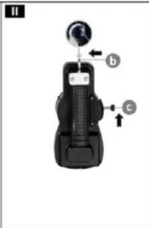
natural_image
Close-up of a gloved hand inserting a blue card into a black handheld device (no visible text or symbols)ŁADOWANIE BATERII
A - Displej 7"
natural_image
Illustration of a medical device with a monitor and handle, no visible text or symbols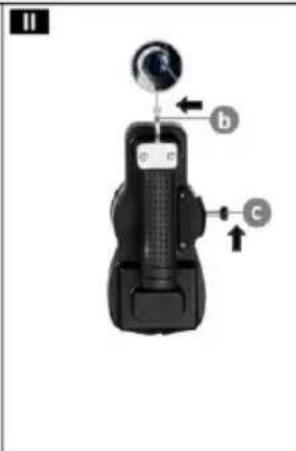
natural_image
Close-up of a gloved hand inserting a blue chip into a black handheld device with circular buttons (no visible text or symbols)NABÍJENÍ BATERIE
natural_image
Illustration of a medical device with a labeled handle and screen (no text or symbols visible)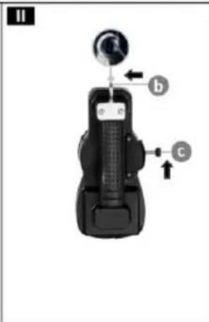
natural_image
Close-up of a gloved hand inserting a blue card into a black remote control device (no visible text or symbols)CHARGEMENT DES BATTERIES
natural_image
Illustration of a medical device with a labeled handle and screen (no text or symbols visible)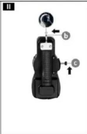
natural_image
Close-up of a gloved hand inserting a blue chip into a black handheld device with circular buttons (no visible text or symbols)CARICARE LA BATTERIA
1 - Maletín
2 - Panel de control
3 - Cable guía
4 - Sonda
5 - Tapa protectora
6 - Carrete de transporte
LISTA DE PIEZAS SBS-EC-300B
2 - Panel de control con cable guía
4 - Sonda
5 - Tapa protectora 220 mm
7 - Tapa protectora 150 mm
8 - Puerto USB
9 - Tarjeta de memoria
SD
10 - Destornillador
11 - Cargador
12 - Junta x6
13 - Llave
14 - Protector
2 - Panel de control con cable guía
4 - Sonda
5 - Tapa protectora 140 mm
7 - Tapa protectora 220 mm
8 - Puerto USB
9 - Tarjeta de memoria SD
10 - Destornillador
11 - Cargador
12 - Junta x4
13 - Llave
14 - Protector
15 - Tapa protectora 100 mm
16 - Cable de conexión
19 - Tornillo x4
20 - Destornillador
A - Pantalla 7"
natural_image
Illustration of a medical device with a labeled handle and screen (no text or symbols visible)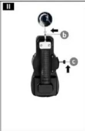
natural_image
Close-up of a gloved hand inserting a blue chip into a black handheld device with circular buttons (no visible text or symbols)RECARGA DE LA BATERÍA
A - Kijelző 7"
natural_image
Illustration of a medical device with a labeled handle and screen (no text or symbols visible)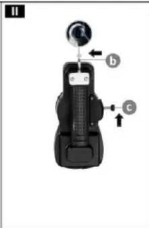
natural_image
Close-up of a gloved hand inserting a blue card into a black handheld device (no visible text or symbols)AKKUMULÁTOR TÖLTÉSE
1 - Kabinet
2 - Kontrolpanel
3 - Styreledningen
2 - Kontrolpanel med
styreledning
4 - Probe
A - 7"Skærm
B – tasten tilbage "ESC"
C - „MENU”- knap
D – Tænd/sluk knap
E - SD-kortindgang
natural_image
Close-up of a gloved hand inserting a blue card into a black handheld device (no visible text or symbols)BATTERIOPLADNING
For the disposal of the device please consider and act according to the national and local rules and regulations.
CONTACT
expondo Polska sp. z o.o. sp. k.
- AUFLADEN DER BATTERIEN
- READ THE MANUAL CAREFULLY AND UNDERSTAND IT BEFORE USE.
- Explanation of symbols
- Operating safety
- Electrical safety
- Workplace safety
- Personal safety
- Safe use of the product
- Rules of use
- Appliance overview
- Preparations for operation
- POSITIONING THE APPLIANCE
- Operating the appliance
- CONTROL PANEL - INTRODUCTION
- CONNECTION OF SBS-EC-300B / SBS-EC-300C
- CONNECTION OF SBS-EC-600B4 / SBS-EC-600B3
- CONNECTING EQUIPMENT / CHARGING BATTERIES
- SD MEMORY CARD INSTALLATION
- CHARGING BATTERIES
- VIDEO RECORDING
- TAKING AN INSPECTION PHOTO
- IMAGE ZOOM CONTROL
- PLAYING STORED VIDEOS/PHOTOS AND REMOVING FILES
- → VIDEO DIRECTORY
- → IMAGE DIRECTORY
- → DELETING FILES
- MENU
- → VIDEO SETTINGS
- → SYSTEM SETTINGS
- COUNTER/SWITCHING METRIC/IMPERIAL UNITS
- Cleaning and maintenance
- DISPOSAL OF WASTE APPLIANCES
- ŁADOWANIE BATERII
- NABÍJENÍ BATERIE
- CHARGEMENT DES BATTERIES
- CARICARE LA BATTERIA
- RECARGA DE LA BATERÍA
- AKKUMULÁTOR TÖLTÉSE
- BATTERIOPLADNING
- CONTACT
Brand : STEINBERG
Model : SBS-EC-600B3
Category : Video camera