
EBM01R24VB - Uninterruptible power supply CONCEPTRONIC - Free user manual and instructions
Find the device manual for free EBM01R24VB CONCEPTRONIC in PDF.

| Product Type | Battery module for uninterruptible power supply (UPS) |
| Brand | Conceptronic |
| Model | EBM01R24VB |
| Nominal battery voltage | 24 Vdc |
| Battery type | Sealed lead-acid maintenance-free battery, 12 V / 9 Ah x 2 units x 2 sets |
| Protection against overloads | Replaceable fuse |
| Dimensions (H x W x D) | 88 x 438 x 430 mm |
| Weight | 15.10 kg |
| Operating temperature | 0 °C to 40 °C |
| Operating relative humidity | 0 to 90 % (non-condensing) |
| Installation | Rack or tower mounting (vertical position) |
| Connections | Battery input and output connectors, grounding cable |
| Package contents | Battery module, user manual, battery cable, mounting brackets, screws, dust caps, grounding cable |
| Safety | Indoor installation only, avoid water and aquariums, disconnect before maintenance, qualified personnel required |
| Maintenance | No user-serviceable parts, battery replacement by qualified personnel |
| Disposal | Do not dispose of with household waste, recycle at an appropriate collection point |
| Warranty / Certifications | CE marking, compliant with applicable directives |
Frequently Asked Questions - EBM01R24VB CONCEPTRONIC
User questions about EBM01R24VB CONCEPTRONIC
0 question about this device. Answer the ones you know or ask your own.
Ask a new question about this device
Download the instructions for your Uninterruptible power supply in PDF format for free! Find your manual EBM01R24VB - CONCEPTRONIC and take your electronic device back in hand. On this page are published all the documents necessary for the use of your device. EBM01R24VB by CONCEPTRONIC.
USER MANUAL EBM01R24VB CONCEPTRONIC
This manual contains important information. Read and follow all instructions carefully during installation and operation. Review this manual before unpacking, installing, or operating the battery modules.
CONTENT
EN....3
DE....10
ES....17
FR....24
IT....31
HU....38
PT....45
PL....52
EN
IMPORTANT SAFETY INSTRUCTIONS
CAUTION! To prevent the risk of fire or electric shock, install in a temperature and humidity controlled indoor area, free of conductive contaminants. (Please see specifications for acceptable temperature and humidity range).
CAUTION! (No User Serviceable Parts): Risk of electric shock, do not remove cover. No user serviceable parts inside. Refer servicing to qualified service personnel.
CAUTION! (Non-Isolated Battery Supply): Risk of electric shock, battery circuit is not isolated from AC power source; hazardous voltage may exist between battery terminals and ground. Test before touching.
CAUTION! Wiring must be done by qualified personnel.
CAUTION! DO NOT USE WITH OR NEAR AQUARIUMS! To reduce the risk of fire, do not use with or near aquariums. Condensation from the aquarium can come in contact with metal electrical contacts and cause the machine to short out.
CAUTION! Do not dispose of batteries in fire as the battery may explode.
CAUTION! Do not open or mutilate the battery, released electrolyte is harmful to the skin and eyes.
CAUTION! A battery can present a risk of electric shock and high short circuit current. The following precaution should be observed when working on batteries.
- Remove watches, rings or other metal objects.
- Use tools with insulated handles.
CAUTION! Make sure everything is turned off and disconnected completely before conducting any maintenance, repairs or shipment.
CAUTION! Connect the Protection Earth (PE) safety conductor before any other cables are connected.
DO NOT INSTALL THE UNIT WHERE IT WOULD BE EXPOSED TO DIRECT SUNLIGHT OR NEAR A STRONG HEAT SOURCE!
SERVICING OF BATTERIES SHOULD BE PERFORMED OR SUPERVISED BY PERSONNEL KNOWLEDGE OF BATTERIES AND THE REQUIRED PRECAUTIONS. KEEP UNAUTHORIZED PERSONNEL AWAY FROM BATTERIES!
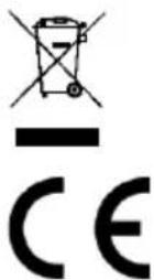
Disposal of waste electrical equipment and batteries: Do not dispose of waste electrical equipment and batteries with household waste. Please hand them to your local recycling point. Batteries should be fully discharged when disposed of. Incorrect storage/disposal can harm the environment and/or cause injury.
CE marking: Conceptronic declares that this product complies with the directives listed in the section 'Declaration of Conformity'.
Pb

Pb


UNPACKING
The box should contain the following:
 | Batteries Module |
 | User's manual |
 | Battery Cable |
 | Rack mount ears (2 PCS) |
 | Flat head screws: M4X8L (8) |
 | Pan head screws: M5X12L (4) |
 | Screw hole dust covers (8) |
 | Ground wire |
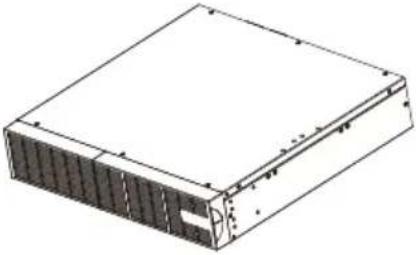
FRONT/REAR PANEL DESCRIPTION
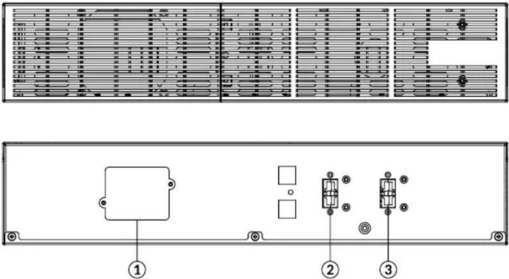
EBM 24V/48V/72V
1. On-board Replaceable Fuse Cover
Replaceable fuse is accessible from the rear panel. It must be done by qualified personnel.
2. Battery Output Connector
Use this output Connector to connect the Battery module to the Power module or to the next Battery module.
3. Input Connector
Use this input connector to daisy chain the next Battery module. Remove the connector cover for access.
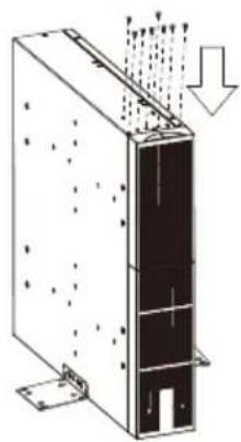
INSTALLATION
HARDWARE INSTALLATION
These batteries modules can be mounted in a rack mount or vertical tower orientation. This versatility is especially important to growing organizations with changing needs that value having the option to position a batteries module on a floor or in a rack mount system. Please follow the instructions below for the respective mounting methods.
SAFETY PRECAUTIONS
CAUTION! To prevent the risk of fire or electric shock, only use the supplied hardware to attach the mounting brackets.
RACKMOUNT INSTALLATION
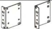
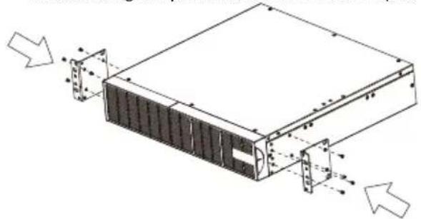
Step 1: Rack mount ears installation
1) Attach the two rack mount ears to the batteries module using the provided screws M4X8L*8pcs.
natural_image
Technical line drawing of a server rack with mounting holes and ventilation ducts (no text or symbols)Step 2 Rack mount rails installation
1) The rails adjust to mount in 48-cm (19-inch) panel racks from 52 to 91.5cm (20.5 to 36 inches) deep. Select the proper holes in the rack for positioning the batteries module in the rack. It takes up position 1 through position 6.
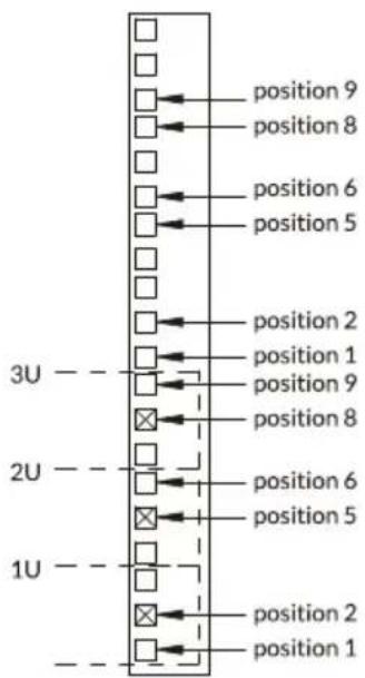
2) Attach the rack mount rail to your rack with two M5X12L screws and two plastic washers at the front of the rack. (Located in position 1 & position 6) Do not tighten the screws. Adjust the rail size on the rail assembly of your rack. Secure the rail to the rear of the rack with two M5X12L screws and two plastic washers. Tighten all screws at the front and rear of the rail. Once completed, perform the same steps for assembling the other rack mount trail.
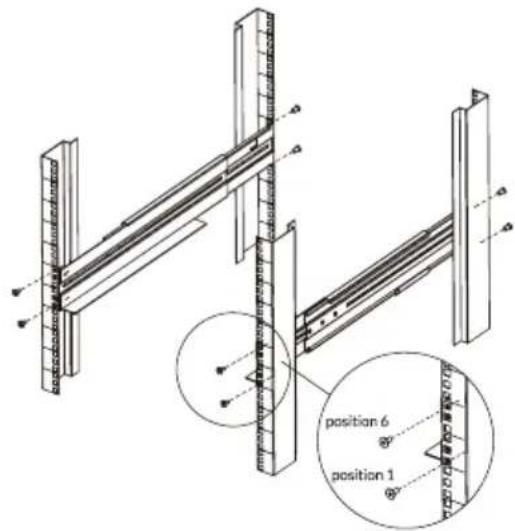
Step 3: Install the batteries module on the rack
Place the batteries module on a flat stable surface with the front of the unit facing toward you. Secure the batteries module to your rack with four M5X12L screws at the front of the rack. (Located in position 2 & position 5).
INSTALLATION
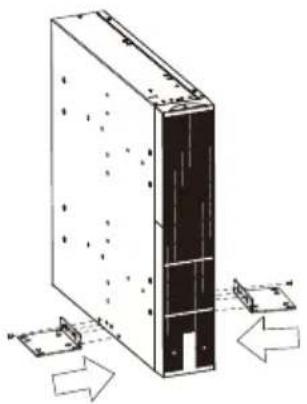
VERTICAL/TOWER INSTALLATION
Step 1: Attach the base stands
Tighten the screws (M5X12*8pcs) of the base stands (rack mount ears) onto the bottom of the batteries module.
natural_image
Technical line drawing of a server rack with mounting holes and directional arrows indicating movement (no text or symbols)Step 2: Attach dust covers
Insert dust cover into the rack mount ear screw holes that are not being used.
natural_image
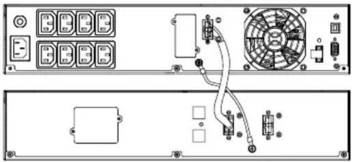
Technical line drawing of a mechanical or electrical component with internal structure and directional arrows (no text or symbols)CONNECTION #1 : POWER MODULE(UPS) WITH ONE BATTERIES MODULE
Step 1: Use the battery cable of the Battery module to connect the Battery module to the Power module.
Step 2: Use screws to fix ground connection.
natural_image
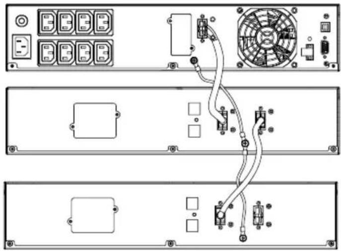
Diagram of an electronic device rear panel showing front, top, and side views with labeled components (no readable text or symbols)CONNECTION #2 : POWER MODULE(UPS) WITH MULTIPLE BATTERY MODULES
Step 1: Connect the 1 ^st Battery module to the Power module using battery cable.
Step 2: Use the battery cable to connect the 2^nd Battery module to the 1^st Battery module.
Step 3: Use screws to fix ground connection.
natural_image
Diagram of a server rack with connected cables and components, no visible text or symbolsINSTALLATION
Battery Installation and replacement
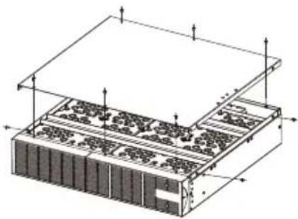
Step1: unscrew and remove the top cover from the battery module.
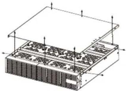
natural_image
Isometric technical diagram of a layered electronic or mechanical assembly with no visible text or symbolsStep2: unscrew and unplug steel straps from the battery module.
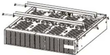
natural_image
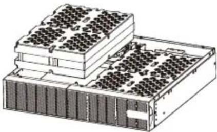
Technical diagram of a multi-tiered battery pack with cooling fins and heat exchangers (no text or labels)Step3: remove the battery pack from the module.
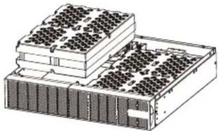
natural_image
Isometric technical drawing of a multi-tiered electronic device with grid-like top structure (no text or symbols)Step4: open the battery pack and replace the batteries.
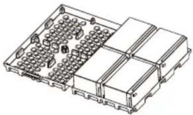
natural_image
Isometric line drawing of a multi-chamber electronic component with no visible text or symbolsStep5: the accumulating block b lower cover .set the steel straps and the top cover again.
natural_image
Isometric technical diagram of a server rack with memory racks and ventilation ducts (no text or labels)TECHNICAL SPECIFICATIONS
| Model | EBM01R24VB | EBM01R48VB | EBM01R72VB |
| Battery | |||
| Sealed Maintenance Free Lead Acid Battery | 12V / 9Ah x2 pcs x2sets | 12V / 9Ah x4 pcs x2sets | 12V / 9Ah x6 pcs x2sets |
| Rated Battery Voltage | 24Vdc | 48Vdc | 72Vdc |
| Overload Protection | Fuse | ||
| Physical | |||
| Dimensions (H x W x D) mm | 88 x 438 x 430 | 88 x 438 x 610 | |
| Weight (kg) | 15.10 | 24.60 | 36.02 |
| Environment | |||
| Operating Temperature | 0°C to 40°C | ||
| Relative Humidity | 0 to 90% (Non-condensing) | ||
EBM 24V/48V/72V
natural_image
Technical line drawing of a server rack with mounting holes and ventilation slots (no text or symbols)natural_image
Technical line drawing of a server rack with mounting holes and directional arrows indicating movement (no text or symbols)natural_image
Diagram of a server rack with heat distribution arrows indicating airflow or heat transfer (no text or symbols)ANSCHLUSS #1: POWERMODUL (USV) MIT EINEM BATTERIEMODUL
ANSCHLUSS #2: POWERMODUL (USV) MIT MEHREREN BATTERIEMODULEN
natural_image
Diagram of three rear panels showing internal components including connectors, switches, and a fan connected by wires (no text or labels)INSTALLATION
natural_image
Isometric technical diagram of a server rack with mounting holes and ventilation grilles (no text or labels)natural_image
Technical illustration of a multi-tiered electronic device with grid-like components and metal frame (no text or symbols)natural_image
Technical line drawing of a multi-tiered electronic device chassis with grid-like components (no text or symbols)natural_image
Isometric technical drawing of a multi-chamber electronic component housing (no text or symbols)natural_image
Isometric technical diagram of a server rack with heat exchangers and memory units (no text or labels)TECHNISCHE DATEN
EBM 24V/48V/72V
natural_image
Technical line drawing of a server rack with mounting holes and ventilation ducts (no text or symbols)natural_image
Technical line drawing of a server rack with mounting holes and directional arrows indicating movement (no text or symbols)natural_image
Diagram of a server rack with heat distribution arrows indicating airflow or heat transfer (no text or symbols)natural_image
Back view diagram of an electronic device showing front panel, rear panel, and internal components (no text or labels)CONNECTION #2 : POWER MODULE(UPS) WITH MULTIPLE BATTERY MODULES
natural_image
Diagram of three rear panels showing internal components including power connectors, switches, and a fan connected by wires (no text or labels present)INSTALACIÓ N
Battery Installation and replacement
natural_image
Isometric technical diagram of a server rack with mounting holes and ventilation grilles (no text or labels)natural_image
Technical diagram of a multi-tiered battery pack with cooling fins and heat exchangers (no text or labels)natural_image
Isometric technical drawing of a multi-tiered electronic device chassis with grid-like components (no text or symbols)natural_image
Isometric technical drawing of a multi-chamber electronic component housing (no text or symbols)natural_image
Isometric technical diagram of a server rack with memory and ventilation slots (no text or labels)EBM 24V/48V/72V
natural_image
Technical line drawing of a server rack with mounting holes and ventilation ducts (no text or symbols)natural_image
Diagram of a server rack with directional arrows indicating movement or force (no text or symbols present)natural_image
Diagram of a server rack with heat distribution arrows indicating airflow or heat flow (no text or symbols)natural_image
Diagram of an electronic device rear panel showing internal components including a fan, buttons, and connectors (no text or labels present)CONNEXION n°2 : MODULE D'ALIMENTATION (UPS) AVEC PLUSIEURS MODULES DE BATTERIES
natural_image
Diagram of a server rack with connected components including fans, switches, and ports (no text or labels)INSTALLATION
INSTALLATION ET REMPLACEMENT DES BATTERIES
natural_image
Isometric technical diagram of a server rack with mounting holes and ventilation grilles (no text or labels)natural_image
Technical diagram of a multi-tiered battery pack with rows of cells and cooling fins (no text or labels)natural_image
Isometric technical drawing of a multi-tiered electronic device with grid-like components (no text or symbols)natural_image
Isometric technical drawing of a multi-chamber electronic component housing (no text or symbols)natural_image
Isometric technical diagram of a layered electronic or mechanical assembly with no visible text or symbolsEBM 24V/48V/72V
natural_image
Technical line drawing of a server rack with mounting holes and ventilation ducts (no text or symbols)natural_image
Technical line drawing of a server rack with directional arrows indicating movement or assembly (no text or symbols)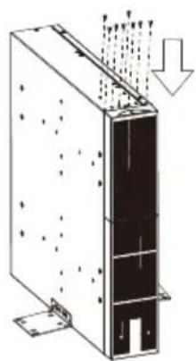
natural_image
Technical line drawing of a mechanical or electrical component with internal structure and directional arrows (no text or symbols)natural_image
Diagram of an electronic device rear panel showing ports, connectors, and a fan with labeled components (no readable text or symbols)CONNECTION #2 : POWER MODULE(UPS) WITH MULTIPLE BATTERY MODULES
INSTALLAZIONE
natural_image
Isometric technical diagram of a server rack with mounting holes and ventilation grilles (no text or labels)natural_image
Technical diagram of a multi-tiered electronic device with grid-like components and mounting brackets (no text or symbols)natural_image
Isometric technical drawing of a multi-tiered electronic device chassis with grid-like components (no text or symbols)natural_image
Isometric line drawing of a multi-chamber electronic component with no visible text or symbolsnatural_image
Isometric technical diagram of a server rack with memory and ventilation slots (no text or labels)SPECIFICHE TECNICHE
EBM 24V/48V/72V
natural_image
Technical line drawing of a server rack with mounting holes and ventilation slots (no text or symbols)natural_image
Diagram of a server rack with directional arrows indicating movement or force (no text or symbols present)natural_image
Technical line drawing of a server rack with ventilation ducts and mounting base (no text or symbols)CSATLAKOZTATÁS #1: TÁ PEGYSÉG (UPS) EGY AKKUMULÁ TOR MODULLAL
natural_image
Diagram of an electronic device rear panel showing internal components including connectors, a fan, and a battery (no text or labels present)CONNECTION #2 : POWER MODULE(UPS) WITH MULTIPLE BATTERY MODULES
natural_image
Diagram of three rear panels showing internal components including connectors, switches, and a fan connected by wires (no text or labels present)TELEPÍTÉS
AKKUMULÁ TOR TELEPÍTÉSE ÉS CSERÉJE
natural_image
Isometric technical diagram of a server rack with mounting holes and ventilation grilles (no text or labels)natural_image
Technical diagram of a multi-tiered electronic device with grid-like components and metal frame (no text or symbols)natural_image
Technical line drawing of a multi-tiered electronic device chassis with grid-like top structure (no text or symbols)natural_image
Isometric technical drawing of a multi-chamber electronic component with no visible text or symbolsnatural_image
Isometric technical diagram of a server rack with memory and ventilation slots (no text or labels)MÜSZAKI ADATOK
EBM 24V/48V/72V
1. Tampa de fusí vel substituí vel integrada
natural_image
Technical line drawing of a server rack with mounting holes and ventilation ducts (no text or symbols)natural_image
Diagram of a server rack with directional arrows indicating movement or force (no text or symbols present)natural_image
Diagram of a server rack with heat distribution arrows indicating airflow or heat transfer (no text or symbols)natural_image
Back view diagram of a server rack with connected modules and fans (no text or labels)INSTALAÇÃ O
natural_image
Isometric technical diagram of a layered electronic or mechanical assembly with no visible text or symbolsnatural_image
Technical diagram of a multi-chamber electronic device with cooling fins and heat exchangers (no text or labels)Passo 3: Retire o conjunto de baterias do módulo.
natural_image
Technical line drawing of a multi-tiered electronic device chassis with grid-like components (no text or symbols)natural_image
Isometric technical drawing of a multi-chamber electronic component housing (no text or symbols)natural_image
Isometric technical diagram of a server rack with memory units and ventilation grilles (no text or labels)ESPECIFICAÇÕ ES TÉCNICAS
EBM 24V/48V/72V
natural_image
Technical line drawing of a server rack with mounting holes and ventilation ducts (no text or symbols)INSTALACJA PIONOWA / WIEŻOWA
natural_image
Technical line drawing of a server rack with mounting holes and directional arrows indicating movement (no text or symbols)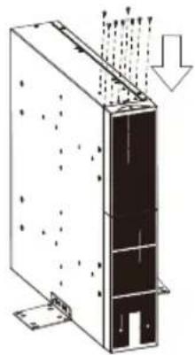
natural_image
Diagram of a server rack with heat distribution arrows indicating airflow or heat flow (no text or symbols)PODŁĄCZENIE nr 1: MODUŁ ZASILANIA (UPS) Z JEDNYM MODUŁEM AKUMULATORÓW
CONNECTION #2 : POWER MODULE(UPS) WITH MULTIPLE BATTERY MODULES
natural_image
Diagram of three rear panels showing internal components including connectors, switches, and a fan connected by wires (no text or labels present)INSTALACJA
INSTALACJA I WYMIANA AKUMULATORÓ W
natural_image
Isometric technical diagram of a server rack with mounting holes and ventilation grilles (no text or labels)natural_image
Technical diagram of a multi-chamber electronic device with cooling fins and heat exchangers (no text or labels)natural_image
Technical line drawing of a multi-tiered electronic device with grid-like top structure (no text or symbols)natural_image
Isometric line drawing of a multi-chamber electronic component housing (no text or symbols)natural_image
Isometric technical diagram of a server rack with memory and ventilation unit (no text or labels)SPECYFIKACJE TECHNICZNE


- CONTENT
- EN
- IMPORTANT SAFETY INSTRUCTIONS
- UNPACKING
- FRONT/REAR PANEL DESCRIPTION
- On-board Replaceable Fuse Cover
- Battery Output Connector
- Input Connector
- INSTALLATION
- HARDWARE INSTALLATION
- SAFETY PRECAUTIONS
- RACKMOUNT INSTALLATION
- Step 1: Rack mount ears installation
- Step 2 Rack mount rails installation
- Step 3: Install the batteries module on the rack
- VERTICAL/TOWER INSTALLATION
- Step 1: Attach the base stands
- Step 2: Attach dust covers
- CONNECTION #1 : POWER MODULE(UPS) WITH ONE BATTERIES MODULE
- CONNECTION #2 : POWER MODULE(UPS) WITH MULTIPLE BATTERY MODULES
- Battery Installation and replacement
- TECHNICAL SPECIFICATIONS
- ANSCHLUSS #1: POWERMODUL (USV) MIT EINEM BATTERIEMODUL
- ANSCHLUSS #2: POWERMODUL (USV) MIT MEHREREN BATTERIEMODULEN
- TECHNISCHE DATEN
- INSTALACIÓ N
- CONNEXION n°2 : MODULE D'ALIMENTATION (UPS) AVEC PLUSIEURS MODULES DE BATTERIES
- INSTALLATION ET REMPLACEMENT DES BATTERIES
- INSTALLAZIONE
- SPECIFICHE TECNICHE
- CSATLAKOZTATÁS #1: TÁ PEGYSÉG (UPS) EGY AKKUMULÁ TOR MODULLAL
- TELEPÍTÉS
- AKKUMULÁ TOR TELEPÍTÉSE ÉS CSERÉJE
- MÜSZAKI ADATOK
- Tampa de fusí vel substituí vel integrada
- INSTALAÇÃ O
- ESPECIFICAÇÕ ES TÉCNICAS
- INSTALACJA PIONOWA / WIEŻOWA
- PODŁĄCZENIE nr 1: MODUŁ ZASILANIA (UPS) Z JEDNYM MODUŁEM AKUMULATORÓW
- INSTALACJA
- INSTALACJA I WYMIANA AKUMULATORÓ W
- SPECYFIKACJE TECHNICZNE
Brand : CONCEPTRONIC
Model : EBM01R24VB
Category : Uninterruptible power supply