
Pro X STX4200 - Cordless brush cutter EGO - Free user manual and instructions
Find the device manual for free Pro X STX4200 EGO in PDF.

| Brand | EGO |
| Model | Pro X STX4200 |
| Product type | Cordless brush cutter |
| Voltage | 56 V |
| Speeds (no load) | Low: 4000 rpm Medium: 5000 rpm High: 6000 rpm |
| Cutting mechanism | Bump feed head |
| Cutting line type | Twisted nylon line, diameter 2.4–2.7 mm |
| Cutting width | 42 cm |
| Weight (without battery) | 3 kg |
| Recommended operating temperature | 0 °C – 40 °C |
| Recommended storage temperature | -20 °C – 70 °C |
| Optimal charging temperature | 5 °C – 40 °C |
| Bluetooth | Yes (band 2402–2480 MHz, max power 10 dBm) |
| Guaranteed sound power level | 94 dB(A) |
| Sound pressure level at ear | 77 dB(A) |
| Vibrations (front handle) | 2.2 m/s² (uncertainty 1.5 m/s²) |
| Vibrations (rear handle) | 1.27 m/s² (uncertainty 1.5 m/s²) |
| Main functions | Trimming grass and weeds along walls, fences, trees, and borders |
| Maintenance and cleaning | Clean with a damp cloth and mild detergent; clean ventilation openings; sharpen or replace the cut-off blade |
| Safety | Wear eye and hearing protection; keep a distance of 15 m; do not use metal blades; remove battery before maintenance |
| Spare parts and repairability | Cutting line (2.4–2.7 mm), cutting head, guard, cut-off blade, compatible battery and charger (BA1400, BA2800, etc.) |
| General information | Use in rain permitted; IPX5 protection rating; do not use the shoulder strap with the BH1000 backpack link simultaneously |
Frequently Asked Questions - Pro X STX4200 EGO
User questions about Pro X STX4200 EGO
0 question about this device. Answer the ones you know or ask your own.
Ask a new question about this device
Download the instructions for your Cordless brush cutter in PDF format for free! Find your manual Pro X STX4200 - EGO and take your electronic device back in hand. On this page are published all the documents necessary for the use of your device. Pro X STX4200 by EGO.
USER MANUAL Pro X STX4200 EGO
natural_image
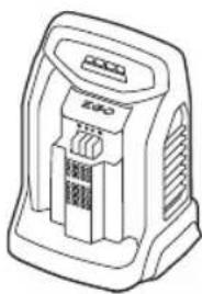
Line drawing of a cylindrical electronic device with internal components (no text or symbols)CH2100E, CH3200E,
CH5500E, CH7000E,
CH7000E-T
natural_image
Line drawing of a portable electronic device with ports and buttons (no text or symbols)B1
natural_image
Technical line drawing of a mechanical component with internal parts and an arrow indicating direction (no text or symbols)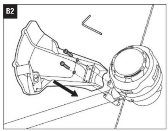
natural_image
Technical line drawing of a mechanical assembly with no visible text or symbols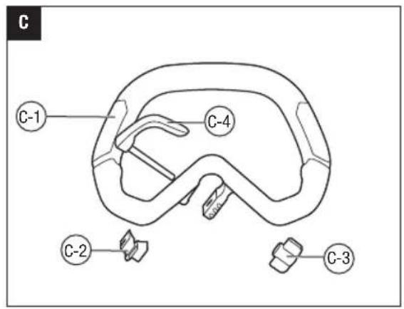

natural_image
Illustration of a hand adjusting a mechanical clamp or grip (no text or symbols present)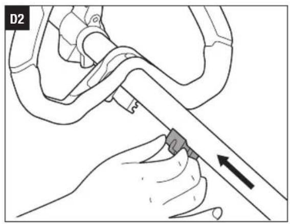
natural_image
Illustration of a hand using a tool to adjust or install a mechanical component, with an arrow indicating direction (no text or symbols present)
natural_image
Technical line drawing of a mechanical assembly with no visible text or symbols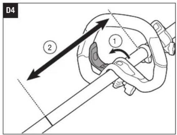
natural_image
Diagram of a mechanical clamp or rope connection with a rotating lever (no text or symbols)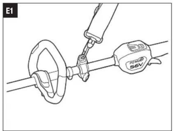
natural_image
Technical line drawing of a cable clamp and connector assembly (no text or symbols)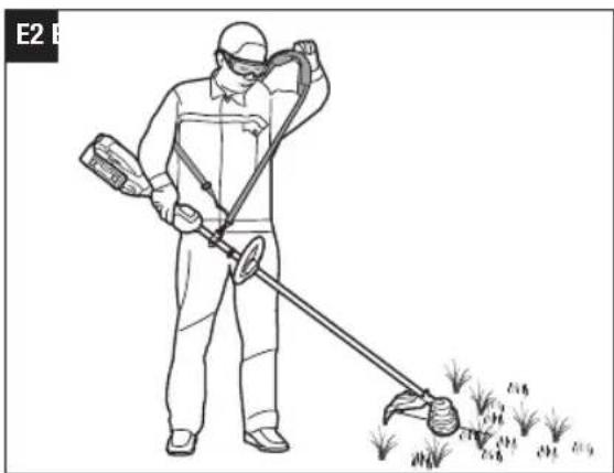
natural_image
Person in protective gear using a handheld device to spray or brush through a field (no text or symbols visible)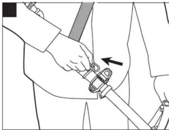
natural_image
Line drawing of a person using a mechanical clamp or wrench to adjust the arm (no text or symbols present)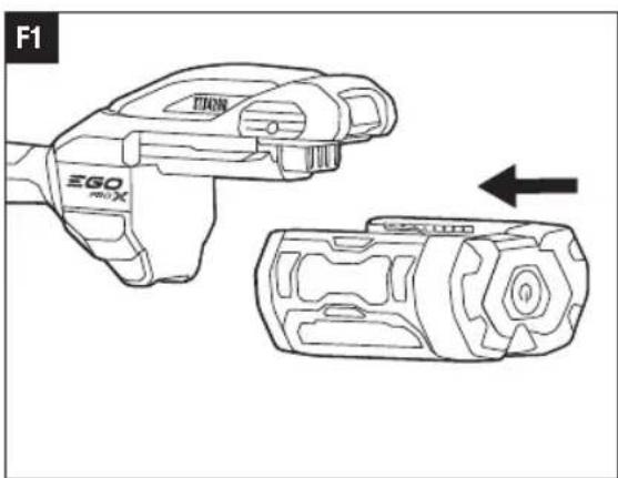
natural_image
Line drawing of a device with two views: top shows a hand holding a device labeled 'TRIN', bottom shows a device with a gear-like structure (no text or symbols)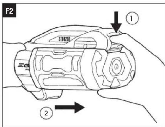
natural_image
Line drawing of a person in protective gear using a long-handled tool to spread grass or leaves (no text or symbols)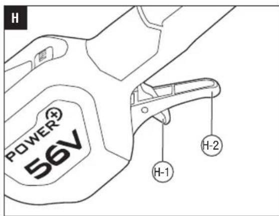
natural_image
Diagram of a water spray system with a central pump and two vertical plants growing in the background (no text or symbols)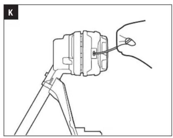
natural_image
Technical line drawing of a mechanical assembly with a hand holding a tool (no text or symbols)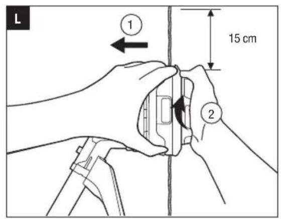

natural_image
Line drawing of hands assembling or adjusting a mechanical component, showing a close-up view with no text or symbols.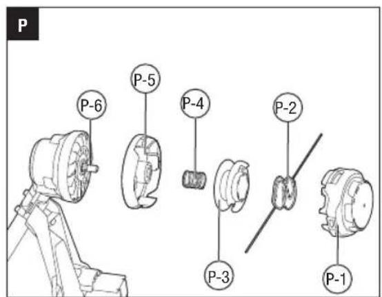
EGO Europe GmbH
The Anchorage, 34 Bridge Street Reading, RG1 2LU, United Kingdom
READ ALL INSTRUCTIONS!
EN

READ OPERATOR'S MANUAL
SAFETY SYMBOLS
WARNING: The operation of any machines can result in foreign objects being thrown into your eyes, which can result in severe eye damage. Before beginning machine operation, always wear safety goggles or safety glasses with side shields and a full face shield when needed. We recommend a Wide Vision Safety Mask for use over eyeglasses or standard safety glasses with side shields.

Safety Alert Read & Understand Operator's Manual


Wear Eye Protection Wear Ear Protection


Do not use metal blades Keep bystanders away


The distance between the machine and bystanders shall be at least 15 m.


Guaranteed sound power level. Noise emission to the environment according to the European community's Directive.


Bluetooth®

n_0 Maximum Speed
Risk of burns. Do not touch hot surface.
Beware of thrown objects
Disconnect battery before maintenance
Waste electrical products should not be disposed of with household waste. Take to an authorized recycler.
The product complies with the applicable European directives.
UK Conformity Assessed.
Direct Current
kg Kilogram
mm Millimeter IPX5 Protection against water jets
cm Centimeter V Voltage
.../min Revolutions or reciprocation per minute
NOTE: The Bluetooth® word mark and logos are registered trademarks owned by Bluetooth SIG, inc. and any use of such marks by EGO is under license.
EN SPECIFICATIONS
| Voltage | 56 V--- | |
| n_0 | Low: 4000 /minMedium: 5000 /minHigh: 6000 /min | |
| Cutting Mechanism Bump Head | ||
| Cutting Line Type | 2.4-2.7 mmylon twist line | |
| Cutting Width 42 cm | ||
| Recommended Operating Temperature | 0°C - 40°C | |
| Recommended Storage Temperature | -20°C - 70°C | |
| Optimum Charging Temperature | 5°C - 40°C | |
| Weight (without battery pack) 3 kg | ||
| Bluetooth Operating Frequency Band | 2402-2480 MHz | |
| Bluetooth Maximum Transmission Power | 10 dBm | |
| Measured sound power level L_WA | 93 dB(A)K=1.1 dB(A) | |
| Sound pressure level at operator's ear L_PA | 77 dB(A)K=3 dB(A) | |
| Guaranteed sound power level L_WA (measured according to 2000/14/EC) | 94 dB(A) | |
| Valuation of vibration a_h : | Front Handle | 2.2 m/s2K=1.5 m/s2 |
| Rear handle | 1.27 m/s2K=1.5 m/s2 | |
■ The declared vibration total value has been measured in accordance with a standard test method and may be used for comparing one machine with another;
■ The declared vibration total value may also be used in a preliminary assessment of exposure.
NOTICE: The vibration emission during actual use of the machine can differ from the declared value in which
the machine is used; In order to protect the operator, user should wear gloves and ear protectors in the actual conditions of use.
PACKAGE (FIG.A1)
DESCRIPTION
KNOW YOUR LINE TRIMMER (Fig. A1)
- Guard
- Line-cutting Blade
- Trimmer Head (Bump Head)
- Cutting Line
- Motor Housing
- Trimmer Shaft
- Quick Adjustable Front Handle
- Speed Mode Button
- Battery-status Indicator
- Speed Indicator
- Bluetooth ^® Indicator
- Variable Speed Trigger
- Lock-off Switch
- Battery-release Button
- Latch
- Ejection Mechanism
- Stop Ring
- 4mm Hex Key
- Rear Handle
- Shoulder Strap Loop
- Shoulder Strap
ASSEMBLY
⚠ WARNING: If any parts are damaged or missing, do not operate this product until the parts are replaced. Use of this product with damaged or missing parts could result in serious personal injury.
WARNING: Do not attempt to modify this product or create accessories not recommended for use with this line trimmer. Any such alteration or modification is misuse and could result in a hazardous condition leading to possible serious personal injury.
WARNING: To prevent accidental starting that could cause serious personal injury, always remove the battery pack from the machine when assembling parts.
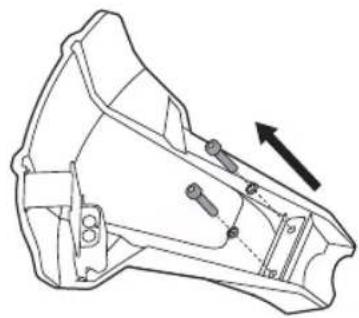
MOUNTING THE GUARD (FIG. B1 & B2)
WARNING: Always wear gloves when mounting or replacing the guard. Take care of the blade on the guard and protect your hand from cutting.
WARNING: Never operate the machine without the guard firmly in place. The guard must always be on the machine to protect the user! When the guard is fixed, never attempt to remove or adjust the guard, if a replacement is needed, it should be performed by a qualified service technician!
NOTICE: Only the guard with icon can be used with line trimmer head and must NOT be used with brush cutter head. Be careful to choose the correct guard when using the machine.
Loosen and remove the two bolts from the guard, align the guard mounting holes with the assembly holes and then lock the guard onto the shaft base with the two bolts, together with two spring washers.
WARNING: Make sure the guard is fixed according to Fig. B1 & B2, any reverse fixing will cause great danger!
MOUNTING AND ADJUSTING THE FRONT HANDLE
- Stop the motor and remove the battery pack from the machine, if installed.
- Loosen the wing nut to separate the adjustable front handle (Fig. C).
| C-1 Front Handle C-3 Wing Nut | |
| C-2 Clamping Block C-4 Quick-release Lever | |
- Position the slant of the front handle upward towards the rear handle. Press the handle onto the upper shaft (Fig. D1).
- Insert the clamping block into the handle slot (Fig. D2).
- Mount the quick-release lever and tighten the wing nut. (Fig. D3).
- Pull the quick-release lever up to move/rotate the front handle to a comfortable operating position (Fig. D4).
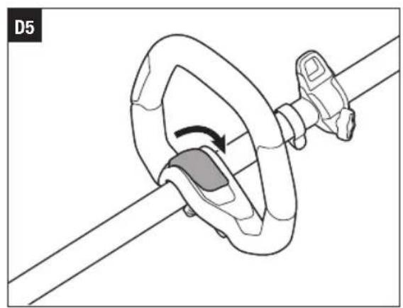
- Fold the quick-release lever to secure the front handle in place (Fig. D5).
WARNING: Never operate the machine without the front handle firmly in place.
MOUNTING SHOULDER STRAP
Depress the strap carabiner to open it and attach it onto the shoulder strap loop (Fig. E1).
There are two ways to release the strap. Take it off from your shoulder directly (Fig. E2) or depress the carabiner and disconnect the shoulder strap from the shoulder strap loop (Fig. E3).
When wearing the strap, no other wearable should interfere with the release and removal of the strap.
When an emergency occurs, take it off from your shoulder immediately, no matter what way the strap is in.
WARNING: For safe and comfortable operation, when using with a 6.0 Ah or higher Ah battery pack, be sure to use the BH1000 EGO Backpack Link to relieve the weight on the user's arms.
WARNING: Do not use shoulder strap and BH1000 EGO Backpack Link at the same time. This will prevent quick emergency release of the machine, resulting in personal injury.
OPERATION
WARNING: Do not allow familiarity with this product to make you careless. Remember that a careless fraction of a second is sufficient to inflict serious injury.
WARNING: Always wear eye protection, along with hearing protection. Failure to do so could result in objects being thrown into your eyes and other possible serious injuries.
WARNING: Do not use any attachments or accessories not recommended by the manufacturer of this product. The use of attachments or accessories not recommended can result in serious personal injury.
WARNING: To prevent serious personal injury, remove the battery pack from the machine before servicing, cleaning, changing attachments or removing material from the unit.
APPLICATIONS
The product may be used in rain.
You may use this product for the purposes listed below: Trimming grass and weeds up against walls, fences, trees and borders.
EN
NOTICE: The machine is to be used only for its prescribed purposes. Any other use is deemed to be a case of misuse.
ATTACHING/DETACHING THE BATTERY
Use only with EGO's battery packs and chargers listed in Fig.A2.
Fully charge before first use.
To Attach
Align the battery ribs with the mounting slots and press the battery pack down until you hear a "click" (Fig. F1).
To Detach
Depress the battery-release button and pull the battery out (Fig. F2).
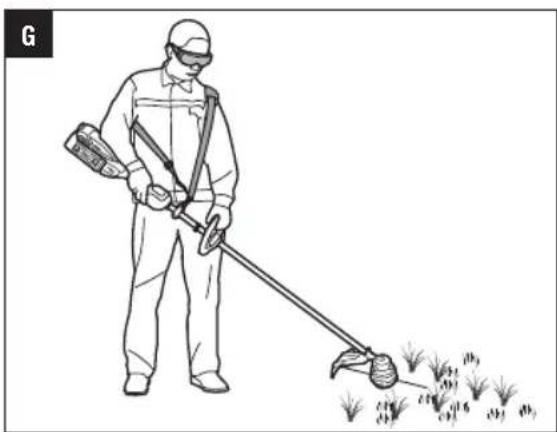
HOLDING THE LINE TRIMMER (Fig. G)
For safe and better operation, put on the shoulder strap across the shoulder. Adjust the shoulder strap length and placement to a comfortable operating position – hold the trimmer with both hands: one hand on the rear handle and the other hand on the front handle.
NOTICE: The trimmer head is parallel to the ground at a proper cutting distance without the operator bending over.

WARNING: When an emergency occurs, take the shoulder strap off from your shoulder immediately, no other what way the strap is on.
STARTING/STOPPING THE MACHINE (Fig. H)
To Start
- Move the lock-off switch forward and then press the variable speed trigger to start.
- The rotational speed of the trimmer head is controlled with the variable speed trigger. More pressure on the trigger results in higher speed; less pressure on the trigger results in lower speed. Adjust the speed to suit the task at hand.
NOTICE: The motor starts only when the lock-off lever is moved forward and the trigger switch is depressed at the same time.
To Stop
Move the machine away from the cutting area and release the variable speed trigger to stop it.

WARNING: Always remove the battery pack from
the machine during work breaks and after finishing work.
H-1 Lock-off Switch H-2 Variable Speed Trigger
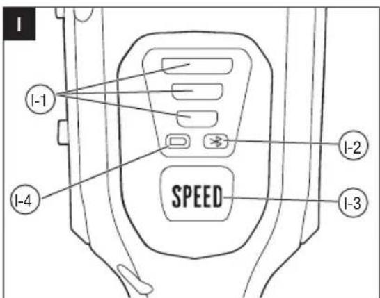
CHANGING SPEED MODE (FIG. I)
The machine features three speed modes.
Every time press the speed mode switch, the speed mode will change.
The speed indicator will display the active speed status: one light for low speed, two lights for medium speed, three lights for high speed. The low speed mode provides better control of the machine and longer operating time per charge.
NOTICE:
The speed mode can be set before the machine is turned on OR during operation.
When the machine is re-started after a break, the speed mode will return to the previous speed.
| I-1 Speed Indicator I-3 Speed Mode Button | |||
| I-2 | Bluetooth® Indicator | I-4 | Battery-status Indicator |
BATTERY-STATUS INDICATOR AND SPEED INDICATOR (FIG. I)
The battery-status indicator shows the charge level and the working status of the battery pack, and the speed indicator shows the working status of the machine as shown in the chart below. The battery-status indicator and the speed indicator will illuminate when the machine is started OR the speed mode button is pressed.
| Indicator Lights | Meaning | ||
| Battery-status indicator | Solid green | Battery charge level of 20% to 100% | |
| Flashing green |  | Battery charge level of 10% to 20% | |
| Solid red | [zc28] | Battery charge level of less than 10% | |
| Flashing red (fast or slow) |  | The battery pack is nearly depleted and needs to be charged immediately. | |
| Solid orange | [VD65] | The battery pack is overheated. Cool the battery pack until the temperature drops below 67°C. See “Battery High-Temperature Protection” below. | |
| Flashing red/ green alternately |  | The battery pack electronics error. Replace the battery pack or contact EGO customer service center. See “Battery Electronics Error Protection” below. | |
| Speed indicator (the illustration shows the high speed) | Solid green |  | The machine is working properly. |
| Solid orange |  | The machine is overheated. Cool the machine until the temperature drops below 80°C. See “Machine High-Temperature Protection” below.NOTICE: To avoid damage to the machine, it will automatically shut down and cool down for 5 minutes after multiple consecutive overheating uses, during which time the orange light remains on as a warning. | |
| Flashing orange |  | The machine is overloaded. See “Machine Overload Protection” below. | |
Battery High-Temperature Protection
If the battery temperature exceeds 70°C during operation, the temperature-protection circuit will immediately shut off the machine to protect the battery pack from overheating damage. The battery-status indicator will glow solid orange. Release the trigger and wait until the overheated battery cools down and the indicator turns green, then restart the machine.
Battery Electronics Error Protection
When the battery pack electronics error occurs, the battery-status indicator will flash red/green alternately and the machine will shut off in 3 seconds. Replace the battery pack or contact EGO customer service center.
Machine Overload Protection
This machine has built-in overload circuit protection. When the machine is overloaded, the motor will stop and the speed indicator will flash orange. Remove the battery pack from the machine, then reattach the battery pack and restart the machine. Decrease the load on the machine, avoid too long or oversize cutting line or cutting on the heavy/woody shrubs.
Machine High-Temperature Protection
If the machine temperature exceeds 90^ C during operation, the temperature-protection circuit will immediately shut off the machine from overheating damage. The speed indicator will glow solid orange. Release the trigger and wait until the overheated
EN
machine cools down and the speed indicator turns green, then restart the machine.
COMMUNICATION TECHNOLOGY
For information on our full range of connected products and services, including connection instructions, please scan the QR Code below or visit www.egopowerplus.eu/connect.

USING THE LINE TRIMMER
Clear the area to be cut before each use. Remove all objects, such as rocks, broken glass, nails, wire, or line that can be thrown or become entangled in the cutting attachment. Clear the area of children, bystanders, and pets. At a minimum, keep all children, bystanders and pets at least 15m away; there still may be risk to bystanders from thrown objects. Bystanders should be encouraged to wear eye protection. If you are approached, stop the motor and cutting attachment immediately.
Before each use, check for damage/worn parts
Check the bump head, guard, shoulder strap, shoulder strap loop, and front handle and replace the parts that are cracked, warped, bent, or damaged in any away.
The line-cutting blade on the edge of the guard can dull over time. It is recommended that you periodically sharpen it with a file or replace it with a new blade.

WARNING: Always wear gloves when mounting or replacing the guard or when sharpening or replacing the line-cutting blade. Note the location of the blade on the guard and protect your hands from injury.
Check for blockage of the trimmer head
■ To prevent blockage, keep the trimmer head clean. Remove grass clippings, leaves, dirt and any other accumulated debris before and after each use.
■ When blockage happens, stop the line trimmer and remove the battery, then remove any grass that may have wrapped itself around the motor shaft or trimmer head.
After each use, clean the trimmer.
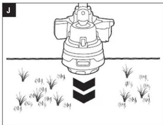
Adjusting cutting line length (Fig. J)
The trimmer head allows the operator to release more cutting line without stopping the motor. As line becomes frayed or worn, additional line can be released by lightly tapping the bump head on the ground while operating the trimmer.
NOTICE: Line release will become more difficult if the cutting line becomes too short.

WARNING: Do not remove or alter the line cutting the assembly. Excessive line length will cause the loss to overheat and may result in serious personal
Line replacement
NOTICE: Always use the recommended nylon cutting line with a diameter of 2.4-2.7mm. Using line other than that specified may cause the line trimmer to overheat or become damaged.

WARNING: Never use metal-reinforced line, wire, or rope, etc. These can break off and become dangerous projectiles.
- Remove the battery pack from the line trimmer.
- Cut 5 m long cutting line, insert the line into the mounting hole inside the eyelet (Fig. K). Push and pull the line from the other side until equal amounts of line appear on both sides of the spool.
- Press, while rotating the lower cover assembly in the arrow direction, to wind the line onto the spool until approximately 15 cm of line is showing on each side (Fig. L).
- Push the lower cover assembly down while pulling on the lines to manually advance the line and to check for proper assembly of the trimmer head.
NOTE: In case the line is pulled into the trimmer head by accident, open the head and pull the cutting line out from the spool. Follow the section "Reloading the cutting line" in this manual to reload the line.
Reloading the cutting line
When the cutting line breaks from the line outlet or the cutting line is not released when the trimmer head is tapped, follow the below steps:
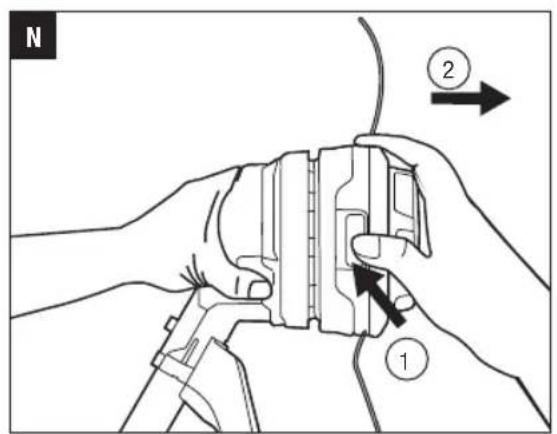
- Press the release tabs on the trimmer head and remove the lower cover assembly by pulling it straight out (Fig. M & N).
NOTE: A flat head screw driver may be required to depress the release tabs. - Remove the cutting line from the spool.
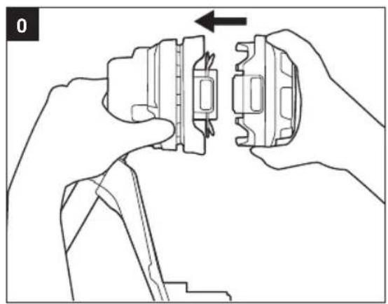
- With one hand holding the trimmer, use another hand to grasp the lower cover assembly and align
the slots in the lower cover assembly with the release tabs (Fig. 0). Press the lower cover assembly until it snaps into place with a distinct click sound.
- Follow the instructions in "Line replacement" to reload the cutting line.
TRIMMER HEAD REPLACEMENT
WARNING: If the head loosens after it is fixed in position, replace it immediately. Never use a trimmer with a loose cutting attachment. Replace a cracked, damaged or worn out cutting head immediately, even if damage is limited to superficial cracks. Such attachments may shatter at high speed and cause serious injury.
Know the trimmer head (Fig. P)
| P-1 | Lower Cover Assembly P-4 | Spring | |
| P-2 | Cutting Line P-5 | Upper Cover | |
| P-3 | Spool Assembly P-6 | Drive Shaft |
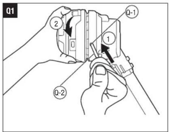
Remove the trimmer head (Fig. Q1)
- Remove the battery pack.
- Insert the hex wrench provided into the shaft-locking hole on the motor housing to act as a shaft lock, hold it with one hand and try to push it inward. At the same time, use the other hand to rotate the trimmer head until the hex wrench is fully inserted.
Q-1 Shaft-locking Hole Q-2 Shaft Lock
- Keep holding the hex wrench, rotate the trimmer head clockwise to remove it.
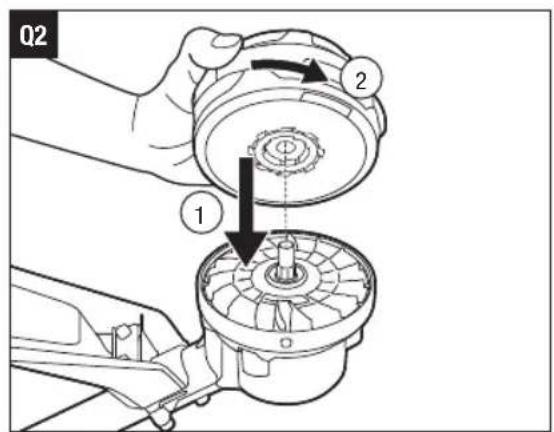
Install the trimmer head
- Lay the trimmer on the ground or the floor with the drive shaft facing upward.
- Align the screw hole on the trimmer head with the drive shaft, install the trimmer head onto the shaft by rotating it counterclockwise (Fig. Q2).
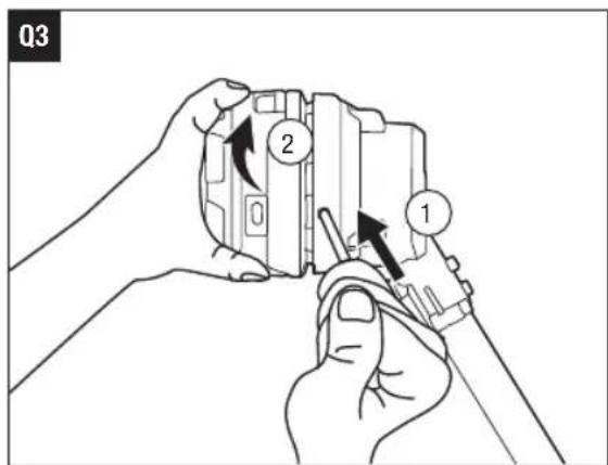
- Install the hex wrench into the shaft-locking hole per the previous section, "Remove the trimmer head". Continue to tighten the trimmer head counterclockwise until fully tightened (Fig. Q3).
MAINTENANCE
WARNING: Before inspecting, cleaning or servicing the unit, stop the motor, wait for all moving parts to stop, and remove the battery pack. Failure to follow these instructions can result in serious personal injury or property damage.
WARNING: When servicing, use only identical replacement parts. Use of any other parts may create a hazard or cause product damage. To ensure safety and reliability, all repairs should be performed by a qualified service technician.
CLEAN THE MACHINE
■ Clean the unit using a damp cloth with a mild detergent.
■ Do not use any strong detergents on the plastic housing or the handle. They can be damaged by certain aromatic oils, such as pine and lemon, and by solvents such as kerosene. Moisture can also cause a shock hazard. Wipe off any moisture with a soft dry cloth.
■ Clear any grass that may have wrapped itself around the motor shaft or trimmer head.
■ Use a small brush or the air discharge of a small vacuum cleaner brush to clean the air vents on the rear housing.
- Keep the air vents free of obstructions.
SHARPENING THE LINE-CUTTING BLADE
WARNING: Always protect your hands by wearing heavy gloves when performing any maintenance on the line-cutting blade.
- Remove the battery pack.
- Remove the line-cutting blade from the guard.
- Secure the blade in a vise.
- Wear proper eye protection and gloves and be careful not to cut yourself.
- Carefully file the cutting edges of the blade with a fine-tooth file or sharpening stone, being careful to maintain the original cutting-edge angle.
- Reinstall the blade onto the guard and secure it in place with the two screws.
EN
STORING THE MACHINE
■ Remove the battery pack from the machine when it is not in use.
■ Clean and maintain the machine thoroughly before storing it.
■ Store the unit in a dry, well-ventilated area, locked-up or up high, out of the reach of children. Do not store the machine on or adjacent to fertilizers, gasoline, or other chemicals.
Protecting the environment
Do not dispose of electrical equipment, used battery and charger into household waste! Take this product to an authorized recycler and make it available for separate collection. Electric machines must be returned to an environmentally compatible recycling facility.
TROUBLESHOOTING
EN
| PROBLEM CAUSE SOLUTION | ||
| Machine will not start or stops working. | The battery pack is not attached to the trimmer.No electrical contact between the trimmer and battery pack.The battery pack charge is depleted.The lock off switch is not being moved forward before depressing the variable speed trigger.The battery pack is too hot.The machine is too hot.The motor is overloaded.The guard is not mounted on trimmer, resulting in an overly long cutting line and motor overload.Heavy cutting line is used.The battery pack has electronics error. | Attach the battery pack to the trimmer.Remove battery pack, check contacts and reinstall the battery pack.Charge the battery pack.Move the lock-off switch forward and then press the variable speed trigger.Remove the battery pack and cool the battery pack until the temperature drops below 67 °C.Remove the battery pack and cool the machine until the temperature drops below 80 °C.The motor will recover when the load is removed. For continuous work, decrease the load on the machine, avoid excessive line length or cutting of heavy/woody shrubs.Remove the battery pack and mount the guard on the trimmer.Use recommended nylon cutting line with diameter 2.4-2.7 mm.Replace the battery pack or contact EGO customer service. |
EN
| PROBLEM CAUSE SOLUTION | ||
| Excessive vibration or noise. | ■ The cutting line is unbalanced.■ The trimmer head is worn out. | ■ Lightly tap the trimmer head on the ground while operating with the trimmer head. If necessary, tap several times.■ Replace with a new trimmer head. Refer to chapter "TRIMMER HEAD REPLACEMENT". |
| Trimmer head will not advance line. | ■ The drive shaft or trimmer head is bound with grass.■ There is not enough line on the spool or the line is broken at the eyelet.■ Line is tangled in the trimmer head.■ Heavy cutting line is used. | ■ Stop the line trimmer, remove the battery and then clean the drive shaft or the trimmer head thoroughly.■ Remove the battery and replace the new cutting line, follow the section "Line replacement" in this manual.■ Remove the battery, reload the cutting line, follow the section "Line replacement" in this manual.■ Use recommended nylon cutting line with diameter 2.4-2.7mm. |
| Grass wraps around the trimmer head and motor housing. | ■ Cutting tall grass at ground level. | ■ Cut tall grass from the top down, removing no more than 20 cm in each pass to prevent wrapping. |
| The blade is not cutting the line. | ■ The line-cutting blade on the edge of the guard has become dull. | ■ Sharpen the line-cutting blade with a file or replace it with a new blade. |
| Cracks on the trimmer head | ■ The trimmer head is worn out. | ■ Replace the trimmer head immediately; follow the section "TRIMMER HEAD REPLACEMENT" in this manual. |
WARRANTY
EGO WARRANTY POLICY
Please visit the website egopowerplus.eu for full terms and conditions of the EGO Warranty policy.
EMBALAGEM (IMAGEM A1)
DESCRIÇÃO
ALTERAR O MODO DA VELOCIDADE (IMAGEM I)
SLIB KNIVEN TIL AFSKÆRING AF SNOREN
VERPAKKING (AFB. A1)
BESCHRIJVING
KEN UW GRASTRIMMER (AFB. A1)
DE BESCHERMKAP MÔNTEREN (AFB. B1 & B2)
ACCUSTATUS-INDICATOR EN SNELHEIDSINDICATOR (AFB. I)
HET APPARAAT OPBERGEN
POLITYKA GWARANCYJNA EGO
LUGEGE KASUTUSJUHENDIT
OHUTUSSÜMBOLID
Corruption Policy for the United States
356357393047550 488mm390s.
modification of the following
hsdsmogb gmdgdmu mzmlusbdnlunm
.הכלההוּרָהוּרָהוּרָהוּרָהוּרָהוּרָהוּרָהוּרָהוּרָהוּרָהוּרָהוּרָהוּרָהוּרָהוּרָה
natural_image
Line drawing of a handheld device with lever and handle (no text or symbols)STX4200
He
- READ ALL INSTRUCTIONS!
- READ OPERATOR'S MANUAL
- SAFETY SYMBOLS
- EN SPECIFICATIONS
- PACKAGE (FIG.A1)
- DESCRIPTION
- KNOW YOUR LINE TRIMMER (Fig. A1)
- ASSEMBLY
- MOUNTING THE GUARD (FIG. B1 & B2)
- MOUNTING AND ADJUSTING THE FRONT HANDLE
- MOUNTING SHOULDER STRAP
- OPERATION
- APPLICATIONS
- EN
- ATTACHING/DETACHING THE BATTERY
- HOLDING THE LINE TRIMMER (Fig. G)
- STARTING/STOPPING THE MACHINE (Fig. H)
- To Start
- To Stop
- CHANGING SPEED MODE (FIG. I)
- NOTICE:
- BATTERY-STATUS INDICATOR AND SPEED INDICATOR (FIG. I)
- Battery High-Temperature Protection
- Battery Electronics Error Protection
- Machine Overload Protection
- Machine High-Temperature Protection
- COMMUNICATION TECHNOLOGY
- USING THE LINE TRIMMER
- Before each use, check for damage/worn parts
- Check for blockage of the trimmer head
- After each use, clean the trimmer.
- Adjusting cutting line length (Fig. J)
- Line replacement
- Reloading the cutting line
- TRIMMER HEAD REPLACEMENT
- Know the trimmer head (Fig. P)
- Remove the trimmer head (Fig. Q1)
- Install the trimmer head
- MAINTENANCE
- CLEAN THE MACHINE
- SHARPENING THE LINE-CUTTING BLADE
- STORING THE MACHINE
- Protecting the environment
- WARRANTY
- EGO WARRANTY POLICY
- EMBALAGEM (IMAGEM A1)
- DESCRIÇÃO
- ALTERAR O MODO DA VELOCIDADE (IMAGEM I)
- SLIB KNIVEN TIL AFSKÆRING AF SNOREN
- VERPAKKING (AFB. A1)
- BESCHRIJVING
- KEN UW GRASTRIMMER (AFB. A1)
- DE BESCHERMKAP MÔNTEREN (AFB. B1 & B2)
- ACCUSTATUS-INDICATOR EN SNELHEIDSINDICATOR (AFB. I)
- HET APPARAAT OPBERGEN
- POLITYKA GWARANCYJNA EGO
- OHUTUSSÜMBOLID
Brand : EGO
Model : Pro X STX4200
Category : Cordless brush cutter