RLT22HB - Log splitter Anova - Free user manual and instructions
Find the device manual for free RLT22HB Anova in PDF.

| Product Type | Log Splitter |
| Brand | Anova |
| Model | RLT22HB |
| Engine | 4-stroke gasoline, 208 cc, 7 HP |
| Splitting Force | 22 tons |
| Maximum Cutting Length | 65 cm |
| Maximum Log Diameter | 50 cm (19 inches) |
| Hydraulic Oil Tank Capacity | 13 L |
| Recommended Engine Oil | SAE30 |
| Wheel Size | 16 inches |
| Weight | 200 kg |
| Power Source | Gasoline |
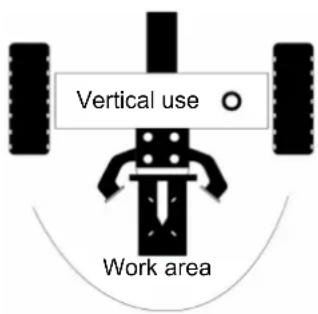
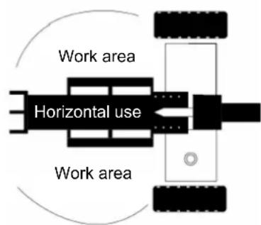
| Main Functions | Splits logs in vertical and horizontal position |
| Maintenance and Cleaning | Clean after use, lubricate the beam, check connections and leaks |
| Safety | Safety devices, stop engine before maintenance, mandatory protective equipment |
| Spare Parts and Repairability | Use original parts, contact an authorized dealer |
| General Information | Legal warranty, responsible recycling, indoor use prohibited |
Frequently Asked Questions - RLT22HB Anova
User questions about RLT22HB Anova
0 question about this device. Answer the ones you know or ask your own.
Ask a new question about this device
Download the instructions for your Log splitter in PDF format for free! Find your manual RLT22HB - Anova and take your electronic device back in hand. On this page are published all the documents necessary for the use of your device. RLT22HB by Anova.
USER MANUAL RLT22HB Anova
natural_image
Industrial machine with mounted components and a flat support frame (no visible text or symbols)ES
ANOVA®

4.2.2. Paso 2
4.2.4. Paso 4
4.2.5. Paso 5
4.2.6. Paso 6
4.2.7. Paso 7
4.2.8. Paso 8
4.2.9. Paso 9
4.2.10. Paso 10
natural_image
Technical line drawing of a mechanical device with labeled component '75' (no text or symbols beyond label)4.2.11. Paso 11
natural_image
Industrial conveyor belt system with a crosshair overlay (no text or symbols visible)
natural_image
Industrial conveyor belt system with conveyor belt and worker (no visible text or symbols)10. CERTIFICADO CE
natural_image
Industrial machine with mounted components and a flat support frame (no visible text or symbols)PT
ANOVA®
- Cilindro
- Motor
- Para-lamas
- Roda
- Elevador de troncos
-
Perna de apoio
-
Barra de reboque
- Tabela
- Estrutura/cunha
- Protetor de bagageira
- Empurrador de tronco
- Válvula de controlo
4.2.2. Passo 2
4.2.4. Passo 4
4.2.5. Passo 5
4.2.6. Passo 6
4.2.7. Passo 7
4.2.8. Passo 8
4.2.9. Passo 9
4.2.10. Passo 10
- Instale a válvula de controlo (75) no cilindro hidráulico.

natural_image
Technical line drawing of a mechanical device with labeled component '75' (no text or symbols beyond label)4.2.11. Passo 11
4.3. Comece
natural_image
Industrial machine with a textured material sample and control panel (no visible text or symbols)
natural_image
Technical diagram of a mechanical assembly with layered material and control panel (no visible text or symbols)natural_image
Industrial machine with mounted components and a flat support frame (no visible text or symbols)FR
anova®
INFORMATIONS SUR CE MANUEL
4.2.2. Étape 2
4.2.4. Étape 4
4.2.5. Étape 5
4.2.6. Étape 6
4.2.7. Étape 7
4.2.8. Étape 8
FR
4.2.9. Étape 9
4.2.10. Étape 10
natural_image
Technical line drawing of a mechanical device with labeled component '75' (no text or symbols beyond label)4.2.11. Étape 11
4.3. Démarrer
natural_image
Industrial conveyor belt system with a crosshair overlay (no text or symbols visible)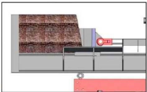
natural_image
Technical diagram of a mechanical assembly with layered material and control panel (no visible text or symbols)5. ENTRETIEN ET TRANSPORT
5.1. Entretien
SOCIÉTÉ DE DISTRIBUTION
MILLASUR, SL
DÉCLARATION DE CONFORMITÉ CE
natural_image
Industrial machine with mounted components and a flat support frame (no visible text or symbols)IT
ANOVA®
4.2.2. Fase 2
4.2.4. Fase 4
4.2.5. Fase 5
4.2.6. Fase 6
4.2.7. Fase 7
4.2.8. Fase 8
4.2.9. Fase 9
4.2.10. Fase 10
natural_image
Technical line drawing of a mechanical device with labeled component '75' (no text or symbols beyond label)4.2.11. Fase 11
4.3. Avvio
natural_image
Industrial conveyor belt system with a crosshair overlay (no text or symbols visible)
natural_image
Industrial conveyor belt system with conveyor belt and worker (no visible text or symbols)5. MANUTENZIONE E TRASPORTO
5.1. Manutenzione
Instructions and user manual
natural_image
Industrial machine with mounted components and a flat support frame (no visible text or symbols)EN
ANOVA®
Anova wishes to congratulate you on choosing one of our products and guarantees you the assistance and cooperation that has always distinguished our brand over time.
This machine is designed to last for many years and be very useful if used according to the instructions in the user manual. We therefore recommend that you read this instruction manual carefully and follow all our recommendations.
For more information or questions, you can contact us through our web support services such as www.anova.es
INFORMATION ABOUT THIS MANUAL
Pay attention to the information provided in this manual and on the appliance for your safety and that of others.
- This manual contains instructions for use and maintenance.
- Take this manual with you when working with the machine.
- The contents are correct at the time of printing.
- We reserve the right to make changes at any time without affecting our legal responsibilities.
- This manual is considered an integral part of the product and must remain with it in the event of loan or resale.
- Ask your dealer for a new manual in case of loss or damage.
READ THIS MANUAL CAREFULLY BEFORE USING THE MACHINE

To ensure your machine provides the best results, please read the operating and safety instructions carefully before using it.
OTHER WARNINGS:
Incorrect use could cause damage to the machine or other objects.
Adapting the machine to new technical requirements could cause differences between the content of this manual and the purchased product.
Read and follow all instructions in this manual. Failure to follow these instructions could result in serious personal injury.
INDEX
- SAFETY INSTRUCTIONS
- PRODUCT DESCRIPTION
- TECHNICAL SPECIFICATIONS
- ASSEMBLY AND OPERATION
- MAINTENANCE AND TRANSPORTATION
- TROUBLESHOOTING
- WARRANTY
- ENVIRONMENT
- EXPLODED VIEW
- CE CERTIFICATE
1. SAFETY INSTRUCTIONS
1.1. Instructions for safe work
▲ Important
Before operating this product, read and follow the instructions below. To prevent injury to yourself and others, you must also follow the safety regulations of your professional association and the safety regulations in force in your country.
Make sure everyone working with the equipment reads the safety instructions. Keep the instructions in a safe place for future reference.
- Be alert at all times. Do not use the equipment if you are tired or under the influence of substances that affect your concentration. A moment of inattention is enough to cause serious injury.
- Familiarize yourself with the equipment before using it. Read and understand all operating instructions.
- Do not use the equipment for unsuitable work.
- Make sure you maintain a secure and balanced stance at all times.
- Stay close to control and safety controls.
- When working with the machine, always carry:
o Safety glasses or a full-face mask. - Safety gloves.
○ Hearing protection. - Steel toe safety footwear.
Do not wear loose clothing or jewelry of any kind as they can get caught or snagged.
- The operator is responsible for third parties within his work area.
- Use of this machine by children or unauthorized persons is prohibited.
- Keep children and pets away from the work area.
- Do not use the machine if there are people nearby.
- Never leave the machine unattended.
- Keep the work area clear. Clutter can cause accidents.
- Do not overload the machine. The job will be done better and safer within the established parameters.
- Use the machine only with the correct safety accessories in place. Do not alter any part of the machine that could compromise its safety.
- Do not modify any part of the machine.
- Do not leave or use the machine in the rain.
- When not in use, store the machine in a dry, secure place out of the reach of children.
- Turn off the engine in the following cases:
- When performing repair work.
- When performing maintenance or cleaning tasks.
- When connecting electrical cables.
- When you fix bugs.
- When transporting the machine.
- If the machine is going to be left unattended, even for short interruptions.
- Inspect the machine for possible faults.
- You should inspect the safety systems to ensure they are working properly before you start using the machine.
- Check that all moving parts are in good condition, functioning properly, and free of jams. All parts must be properly installed and comply with all regulations to ensure proper machine operation.
- Damaged parts and guards must be replaced or repaired by a specialized workshop.
○ If the warnings printed on the machine are damaged or illegible, they must be replaced immediately.
1.2. Additional safety instructions
- The log splitter should be used by one person only.
- The machine should only be used by authorized persons who have read and understood the instructions.
- For safety, use protective equipment (footwear and mask or safety glasses, gloves, etc.).
- Never attempt to cut logs containing spikes, wires or other similar objects.
- Pre-cut logs and wood chips are dangerous in the work area; the operator could slip, trip, or fall. Always keep the work area clear.
- Never place your hands on or near moving parts when the machine is on. Keep a safe distance from the log, the pusher blade, and the wedge to avoid serious injury.
- Before you start splitting logs, make sure the splitting wedge has been lubricated to allow for smooth operation.
1.3. Residual risks
▲ Important
Even if the product complies with relevant safety regulations, there may be residual risks given the characteristics of the equipment and the work for which it was designed.
Residual risks can be minimized by following the safety instructions.
- You will reduce the risk of personal injury and damage to equipment by following these instructions and exercising caution.
- Failure to follow these safety instructions may result in injury to the operator or damage to property.
- Lack of care, improper use, or failure to follow safety rules can cause injuries to hands and fingers when the wedge is in motion.
- There is a risk of electrocution if you use non-approved electrical connections.
- There is a risk of hearing loss when working with the machine without protection for long periods.
Note: Even if you take preventive measures, there may be residual risks that are not obvious.
1.4. Safety symbols

Read the operating and safety instructions carefully before starting to use the machine. Serious injury may result if the safety instructions are not followed.
Wear safety footwear to protect your feet from falling logs.
EN

Wear protective gloves to protect your hands from splinters.
Use hearing protectors when working with the machine.
Wear full-face protection when operating the machine to protect your eyes from flying chips and other objects.
Keep the work area clear. Clutter can lead to accidents.
The presence of oil poses a fire hazard and may explode. Smoking and open flames are prohibited.
Used oil must be managed at an oil collection point. Do not pour old oil on the ground or down drains or mix it with other waste.
Do not remove or modify any safety guards or systems.
Always be aware of the movement of the blade.
Risk of cutting or crushing. Never touch the hazardous areas when the blade is moving.
Do not remove stuck logs by hand.
Always turn off the engine before beginning any maintenance, repair, or cleaning tasks.
No one other than the operator should be in the work area. Keep other people and animals out of the danger zone (minimum distance of 5 m).
Make sure the machine is operated in a well-ventilated area.
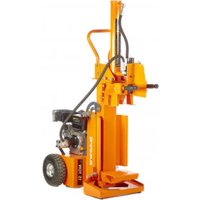
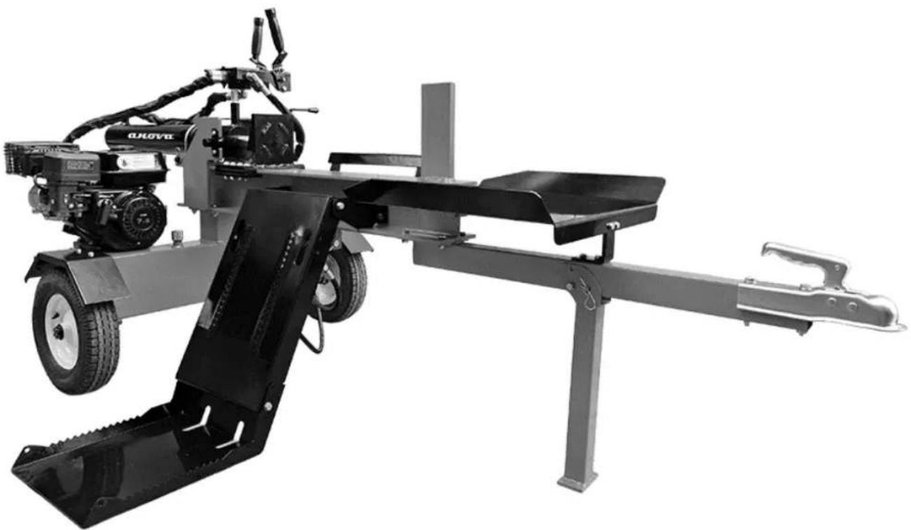
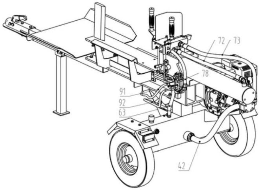
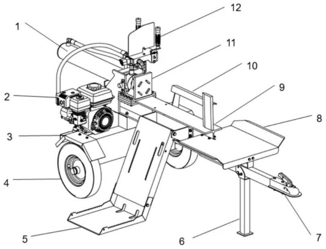
2. PRODUCT DESCRIPTION
2.1. Parts of the machine

- Cylinder
- Engine
- Mudguards
- Wheel
- Log lift
-
Support leg
-
Tow bar
- Table
- Structure/wedge
- Trunk protector
- Trunk pusher
- Control valve
Important note: For all operations relating to the use and maintenance of the engine not described in this manual, please refer to the corresponding manuals.
3. TECHNICAL SPECIFICATIONS
| Characteristics | |
| Engine Gasoline – 4-stroke | |
| Cylinder capacity | 208cc |
| Shear force 22 tons | |
| Power | 7 HP |
| Maximum cutting length 65 cm | |
| Maximum trunk diameter | 19" - 50 cm |
| Wheel size 16" | |
| Hydraulic oil tank capacity | 13L |
| Recommended engine oil SAE30 | |
| Weight | 200 kg |
Note: Due to design improvements and/or changes in specifications, this manual may be modified without prior notice and without the need to change the document.
4. ASSEMBLY AND OPERATION
4.1. Unpacked
After unpacking the product, check the contents of the box:
- Place the shipping box on a solid, flat surface.
- Always be careful with parts such as the engine, oil tank, wheels, tow bar, support legs, and accessories.
- Check that all parts and accessories are in the box before beginning assembly.
Attention
Make sure it contains all the indicated materials. Check that it has not been damaged during shipping. Immediately report any damage or missing parts to the distributor or supplier, as claims filed after this date will not be honored.
4.2. Mounting
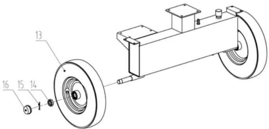
4.2.1. Step 1
- Secure the tire (13) to the oil tank on both sides using the M24x2 nut (14), cotter pin (15) and wheel cover (16).
EN
4.2.2. Step 2
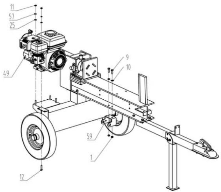
- Remove the hydraulic cylinder and secure it with the cylinder lock (58), the M8x25 bolt (56), the ø8 flat washer (57) and the ø8 flat washer (25).

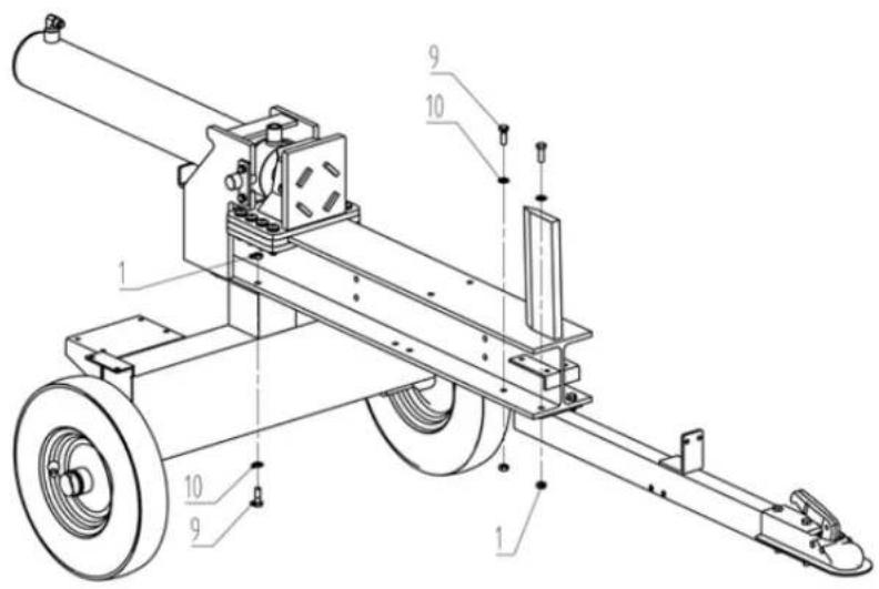
4.2.3. Step 3
- Install the oil tank to the body frame using the M10x30 bolt (9), 10x 20x2 flat washer (10) and M10 lock nut (1).
- Install the tow bar to the body frame using the M10x30 bolt (9), the 10x 20x2 flat washer (10) and the M10 lock nut (1).
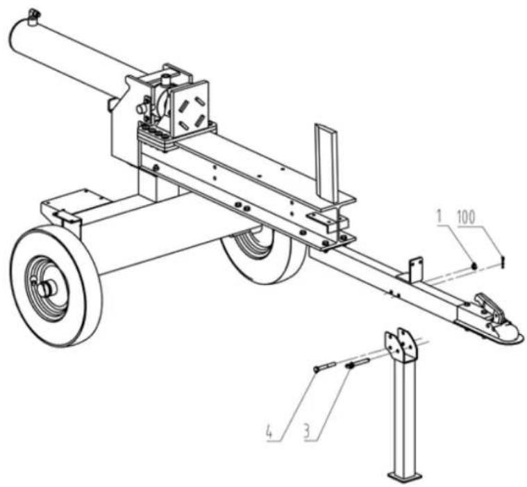
4.2.4. Step 4
- Install the support leg to the tow bar using the pin (3), the R ø1.6x38 pin (100), the M10x75 bolt (4) and the M10 lock nut (1).
4.2.5. Step 5
- Install the gasoline engine (49) to the oil tank using the M8x40 bolt (12), the ø8 flat washer (25), the ø8 flat washer (57) and the M8 lock nut (11).
- Install the cylinder support (59) using the M10x30 bolt (9), the 10x 20x2 flat washer (10) and the M10 lock nut (1).
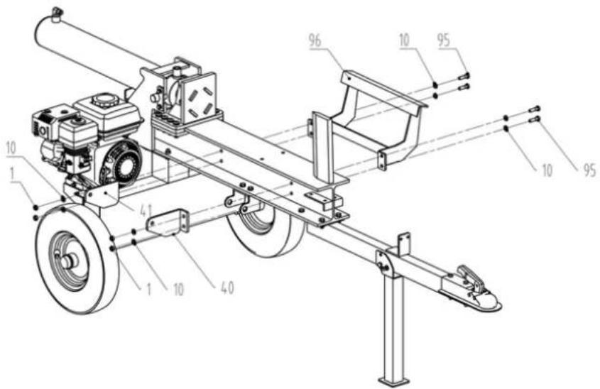
4.2.6. Step 6
- Install the log lift bracket (right) (40), log lift bracket (left) (41) and log guard (96) using the M10x35 bolt (95), 10x 20x2 flat washer (10) and M10 lock nut (1).

4.2.7. Step 7
- Install the log lifting cylinder (31) to the cylinder holder using the cylinder pin (29) and the R pin ø3x73 (30).
- Install the other side of the log lifting cylinder (31) to the log lifter using the cylinder pin (29) and the R pin 3× 73 (30).

4.2.8. Step 8
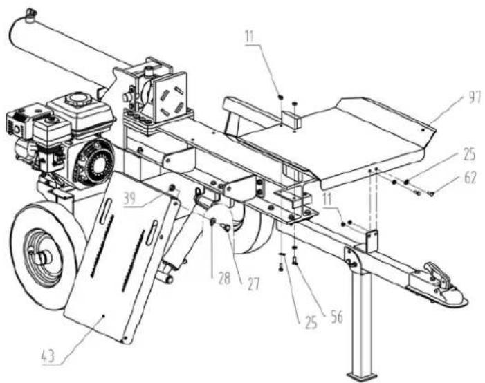
- Install the log lifter (43) to the log lifter bracket using the M12x30 bolt (27), the 12x 24x2.5 flat washer (28) and the M12 lock nut (39) on both sides.
- Install the log table (97) to the body frame using the M8x25 bolt (56), the ø8 flat washer (25) and the M8 lock nut (11).
- Connect the other side to the tow bar using the M8x20 bolt (62), the ø8 flat washer (25) and the M8 lock nut (11).
4.2.9. Step 9
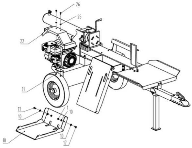
- Install the log lift plate (18) to the log lift using the M10x25 bolt (17), the ø10xø20x2 flat washer (10) and the M10 lock nut (1).
- Install the wheel fender (22) on both sides using the M8x16 bolt (26), the ø8 flat washer (25) and the M8 lock nut (11).
4.2.10. Step 10
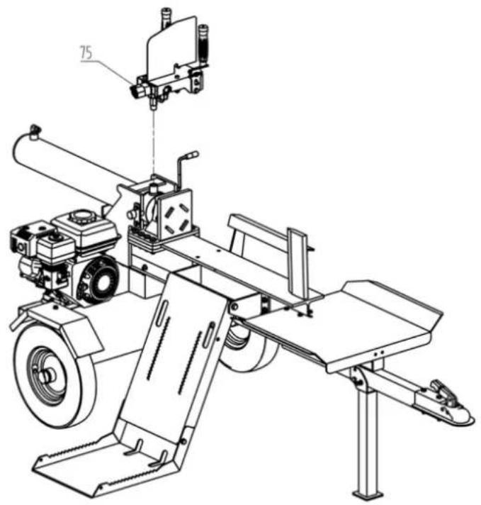
- Install the control valve (75) on the hydraulic cylinder.
natural_image
Technical line drawing of a mechanical device with labeled component '75' (no text or symbols beyond label)4.2.11. Step 11
- Install all oil pipes according to the following pictures.
4.3. Start-up
- Make sure the machine is properly assembled.
-
Before each use of the machine, make sure that:
-
There are no faulty connections (tears or cuts etc.).
- Do not use defective electrical cables.
- The machine has not suffered any damage.
- All nuts are tight.
- There are no leaks from the hydraulic system.
- Check the oil level.
4.3.1. Ventilation
- Vent the hydraulic system before starting the log splitter.
- Unscrew the vent screw without removing it completely so that air can escape from the oil tank.
- Leave the vent open while using the machine.
- Close the vent screw before moving the machine as oil may escape.
Attention
Failure to vent the hydraulic system will result in trapped air damaging the seals, resulting in permanent damage to the machine.
4.3.2. Instructions for commissioning
-
Load a log into your holder and rest it on the base plate/log holder.
-
Serious accidents can occur when others are allowed into the work area. Keep everyone out of the work area while using the machine.
- Make sure your hands are away from crush hazard areas.
- Push the control valve handle forward with both hands to split the log.
- Push the control valve handle back with both hands to return the wedge to its original position.
- Safely remove split wood from the work area.
▲ Important
Do not use the machine near drums, gas or fuel pipes, or any other flammable material.
Ensure that the work area meets the following requirements:
- There is no risk of slipping.
- The ground is level.
- There are no obstacles.
- There is enough light.
Note: Keep hands away from the blade. Serious injury may occur. The blade can cause serious injury. Wear eye and hearing protection while cutting..
4.4. Operating instructions
4.4.1. Correct use
- Use the log splitter only for splitting logs.
- Before using the log splitter, remove any foreign objects, such as spikes, wires, or concrete, from the log.
- By using this product, the user agrees to comply with the manufacturer's instructions for use, maintenance, and repair, and to follow the safety instructions included in this manual.
- The manufacturer does not authorize any use of this machine not indicated in the manual.
- Any modification to the product exempts the manufacturer from all liability for any damage that may result.
- Only those familiar with and informed of the risks involved in using the product may prepare, use, and perform maintenance tasks.
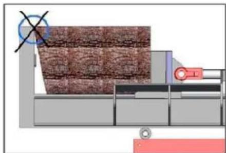
4.4.2. Splitting logs with an inclined surface
natural_image
Industrial conveyor belt system with a crosshair overlay (no text or symbols visible)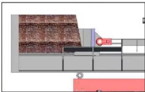
natural_image
Industrial conveyor belt system with conveyor belt and worker (no visible text or symbols)5. MAINTENANCE AND TRANSPORTATION
5.1. Maintenance
Before performing cleaning and maintenance tasks, the log splitter must be placed in maintenance mode.
- Turn off the engine.
- Move the control valve handle back and forth to relieve hydraulic pressure.
- Wear protective gloves to avoid hand injuries.
After performing maintenance, ensure that all guards, shields, and safety features are in place. Failure to follow this warning may result in serious injury.
Refer to the engine owner's manual for engine maintenance.
| That | When | As |
| Hoses | Each use | Inspect for exposed wire mesh and leaks. Replace all worn or damaged hoses before starting the engine. |
| Hydraulic fittings | Each use | Inspect for cracks and leaks. Replace all damaged accessories before starting the engine. |
| Nuts and bolts | Each use | Check for loose bolts |
| Beam | Each use | Apply grease to the surface of the beam |
| Moving parts | Each use | Clear debris |
After cleaning and maintenance tasks have been performed, any dismantled safety devices must be correctly replaced and the relevant functional tests must be performed.
Use only manufacturer-approved parts. Using parts not approved by the manufacturer could cause damage or injury.
Make sure you have removed any tools from the machine after performing maintenance tasks.
Other maintenance or repair tasks not described in this manual must be carried out by a qualified professional.
To ensure a long and reliable service life, you should perform the following maintenance tasks frequently.
Follow the following instructions in the order in which they appear to keep the machine in good condition:
- Clean the machine carefully after use.
- Loosen any fasteners or grips.
- Check for damaged or worn parts.
- Remove any remaining resin.
- Lubricate the piston column frequently or use an environmentally friendly spray oil.
- Regularly check that the connections are tight and that there are no leaks from the hydraulic pipes or connections.
- Correct any assembly or placement errors of protective elements.
6. TROUBLESHOOTING
Warning
Do not perform any maintenance while the engine is running. Turn off the machine and unplug it.
| Problem | |
| The cylinder rod does not move | SOLUTION: A,D,E,H,J |
| Slow speed of the cylinder rod when extending or retracting | SOLUTION: A,B,C,H,I,K,L |
| The wood does not split or splits very slowly. | SOLUTION: A,B,C,F,I,K |
| The engine stalls during splitting SOLUTION: G,L | |
| The engine stalls under low load conditions | SOLUTION: D,E,L,M |
| Possible cause | Solution |
| A - Insufficient oil to pump | Check the oil level in the tank |
| B - Air in oil | Check the oil level in the tank |
| C - Excessive vacuum at the pump inlet | Check the pump inlet hose for blockage or kinks. |
| D - Blocked hydraulic lines | Flush and clean the hydraulic system |
| E - Control valve blocked | Flush and clean the hydraulic system |
| F - Low control valve setting | Adjust the control valve with a pressure gauge |
| G - High control valve setting | Adjust the control valve with a pressure gauge |
| H - Damaged control valve | Contact your official distributor |
| I - Internal control valve leakage | Contact your official distributor |
| J - Internal cylinder leak | Contact your official distributor |
| K - Internally damaged cylinder | Contact your official distributor |
| L - Engine control out of adjustment | Adjust the idle control nuts |
| M - The engine is loaded during idle mode | Use a shorter trunk to allow the engine to accelerate before contact. |
Note: If you have any questions or problems persist after performing the above operations, please contact your dealer or service center.
7. WARRANTY
If your product experiences a manufacturing defect during the established warranty period, please contact or go to your point of sale directly with the necessary documentation.
Your purchase invoice must be kept as proof of the purchase date. Your tool must be returned to your dealer in acceptable, clean condition, in its original molded case, if applicable, accompanied by your corresponding proof of purchase.
7.1. Warranty period
The legal warranty period for the product begins on the original date of purchase by the initial purchaser and will last as long as established by the Royal Decree-Law on the protection of consumers and users against situations of social and economic vulnerability for the year corresponding to the time of purchase of the product.
Some countries do not allow limitations on how long an implied warranty lasts or do not allow the exclusion or limitation of consequential or incidental damages, so the above limitation and exclusion may not apply to you. This warranty gives you specific legal rights, and you may also have other rights that vary from state to state or country to country.
7.2. Exclusions
This warranty does not cover damage to the product or performance problems caused by:
- Natural wear and tear due to use.
- Misuse, negligence, careless operation or lack of maintenance.
- Defects caused by improper use, damage caused by manipulation carried out by personnel not authorized by Anova, or use of non-original spare parts.
- Defects in normal wear parts, such as bearings, brushes, cables, plugs, or accessories such as drills, bits, saw blades, etc.
- Damage or defects resulting from abuse, accidents or alterations.
- Incorrect use and storage (explicit reference that the rules described in the operating instructions have not been followed).
- Wear caused by the customer (e.g. broken saw blades, consumed carbon brushes, etc.).
- Wear and secondary damage due to lack of maintenance, repair, lubricants (e.g., overheating damage due to blocked cooling slots, bearing damage due to dirt, frost damage, etc.)
- Damage as an obvious result of overuse/overload.
- Damage caused by inappropriate supplies (e.g., incorrect fuel)
- Load-induced fracture of housing components or accessories due to abnormal stress
- Load-induced deformation of housing components or accessories due to abnormal stress.
- Damage resulting from the operation of supplies that are overfilled or leak due to improper storage, inappropriate cleaning agents, or other damaging chemical components.
- Damage due to improper exposure to extreme temperatures (e.g., frost fractures, thermal deformation of components, etc.)
- Damage from permanent exposure to ultraviolet radiation.
EN
- Damage caused by inadequate maintenance.
- Any damage caused by non-compliance with the instruction manual
- Any product that has been attempted to be repaired by an unqualified professional.
- Any product connected to an improper power source (amps, voltage, frequency).
- Any damage caused by external influences (water, chemicals, physical, impacts) or foreign substances.
- Use of unsuitable accessories or parts.
- It does not include defects due to normal wear and tear, nor does it cover damage or defects resulting from abuse, accidents or alterations, nor transportation costs.
The warranty is also void if the product has been altered or modified, or if the machine's trademark/serial number has been defaced or removed.
Routine maintenance, tune-ups, adjustments, or normal wear and tear are not covered under this warranty.
This manual does not cover all possible warranty exclusions; for more information, please contact your nearest Anova dealer.
7.3. In case of incident
The warranty must be properly completed with all the requested information and accompanied by the purchase invoice.
Anova reserves the right to reject any claim where the purchase cannot be verified or where it is clear that the product was not properly maintained (maintenance, clean ventilation slots, lubrication, carbon brushes regularly serviced, cleaning, storage, etc.).
Private use is defined as personal domestic use by an end consumer. Commercial use, on the other hand, refers to all other uses, including uses for business, income-generating, or rental purposes. Once a product has been used for commercial purposes, it will henceforth be considered a commercial product for the purposes of this warranty.
These are our standard warranty terms, but occasionally there may be additional warranty coverage not specified at the time of publication. For more information, please contact your nearest authorized Anova dealer or visit www.millasur.com.
Warranty service is only available through official Anova dealers. You can find your nearest dealer on our dealer map at www.anova.es.
8. ENVIRONMENT


It's essential to ensure that products and their components are disposed of responsibly to protect the environment. Below, you can find general guidelines for the proper disposal of various materials used in your machine.
Dispose of your machine in an environmentally friendly manner. Machines should not be disposed of with household waste. Their plastic and metal components can be sorted according to their nature and recycled.
When disposing of machinery or metal products, keep in mind that their metal components, such as iron, steel, or aluminum, must be properly recycled in metal recycling facilities. This will contribute to the possibility of reusing them in the manufacture of new products.
Oils and Fuels
Used oils and fuels, among other things, must be properly recycled. Do not pour these liquids into drains, soil, rivers, lakes, or seas, as they can cause serious environmental damage. Direct them to a recycling center or specialized collection point. This process helps prevent water and soil contamination and, if possible, allows the oils to be reused safely.
Plastics
Plastics should be separated and taken to specific recycling points. Do not dispose of them with general household waste. Plastics can be recycled, contributing to waste reduction.
Cardboard
Packaging materials, such as cardboard, are recyclable. Be sure to separate clean, dry cardboard and place it in designated recycling containers or at an official waste collection point. Do not dispose of it with household waste.
Batteries
Batteries, accumulators, and other electronic components from the machines must be disposed of at designated collection points to prevent the release of toxic substances into the environment. Do not dispose of them with regular trash. Take them to appropriate recycling centers for safe and responsible handling.
By following these guidelines, you are contributing to environmental protection and resource conservation. For more information on disposal and recycling, please contact your local authorities for further information.
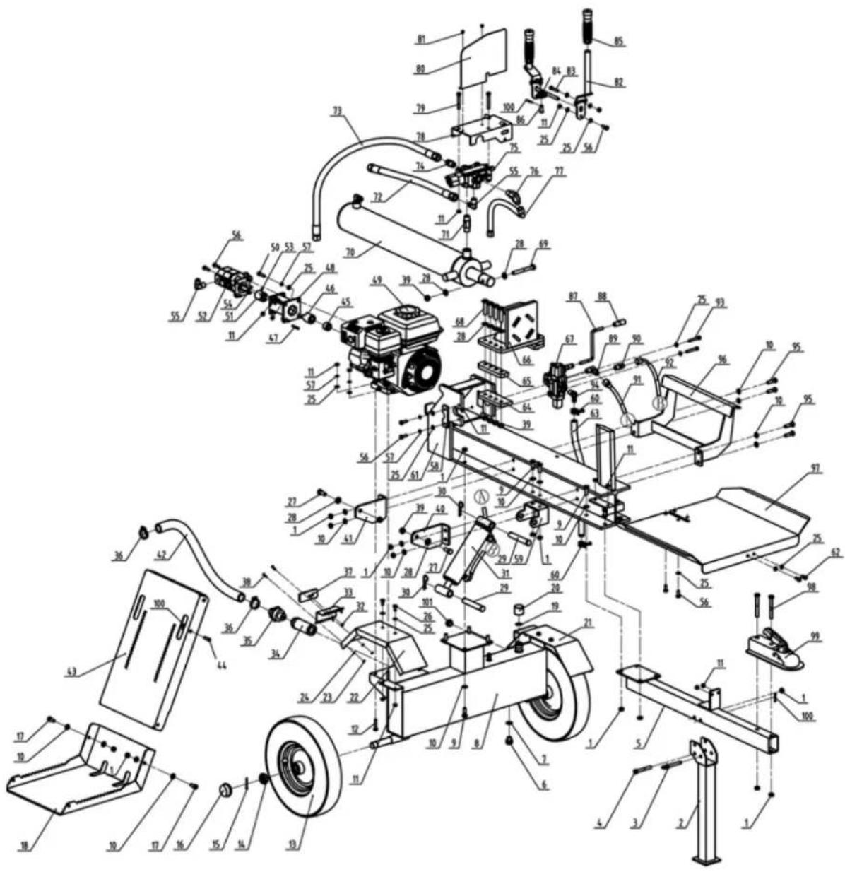
9. EXPLODED VIEW
DISTRIBUTION COMPANY
MILLASUR, SL
EC DECLARATION OF CONFORMITY
In compliance with the various EC directives, it is hereby confirmed that, due to its design and construction, and according to the CE mark printed on it by the manufacturer, the machine identified in this document complies with the relevant and fundamental health and safety requirements of the aforementioned EC directives. This declaration qualifies the product for displaying the CE symbol.
If the machine is modified and this modification is not approved by the manufacturer and communicated to the distributor, this declaration will lose its value and validity.
Machine name: WOOD CHIPPER
Model: RLT22HB
Recognized and approved standard to which the following are adapted:
Directive 2006/42/EC
2014/30/EU
97201/2553/C
Tested according to regulations:
EN 55012:2007 + A1:2009
EN 609-1:2017
Company seal
MILLASUR, S.L.U.
Ria Eduardo Pondal,23 - Pol.Emp..Siguelro
15688-Oroso-A Coruña
Tel.(+34) 981 69 64 65 - Fax (+34) 981 69 08 61
e-mail: millasur@millasur.com
CIF: B-15 749 922
09/09/2025
Brennholzbrecher
RLT22HB
ANOVA®
natural_image
Industrial machine with mounted components and a flat support frame (no visible text or symbols)DE
ANOVA®
4.2.2. Schritt 2
4.2.4. Schritt 4
4.2.5. Schritt 5
4.2.6. Schritt 6
4.2.7. Schritt 7
4.2.8. Schritt 8
4.2.9. Schritt 9
4.2.10. Schritt 10
natural_image
Technical line drawing of a mechanical device with labeled component '75' (no text or symbols beyond label)4.2.11. Schritt 11
4.3. Start-up
natural_image
Industrial conveyor belt system with a crosshair overlay (no text or symbols visible)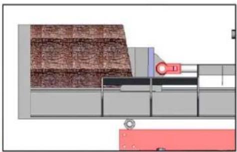
natural_image
Technical diagram of a mechanical assembly or processing unit with layered materials and control panels (no visible text or symbols)10. CE-ZERTIFIKAT
natural_image
Industrial machine with mounted components and a flat support frame (no visible text or symbols)NL
ANOVA®
ANDERE WAARSCHUWINGEN:

2. PRODUCTBESCHRIJVING
2.1. Machineonderdelen
- Cilinder
- Motor
- Spatborden
- Wiel
- Boomstamlift
-
Steunpoot
-
Trekhaak
- Tabel
- Structuur/wig
- Kofferbakbeschermer
- Kofferbakduwer
- Regelklep
4.2.2. Stap 2
4.2.4. Stap 4
4.2.5. Stap 5
4.2.6. Stap 6
- Monteer de houtliftbeugel (rechts) (40), houtliftbeugel (links) (41) en houtbescherming (96) met behulp van de M10x35-bout (95), ø10xø20x2 platte ring (10) en M10-borgmoer (1).
4.2.7. Stap 7
4.2.8. Stap 8
NL
4.2.9. Stap 9
4.2.10. Stap 10
natural_image
Technical line drawing of a mechanical device with labeled component '75' (no text or symbols beyond label)4.2.11. Stap 11
4.3. Opstarten
natural_image
Industrial conveyor belt system with a crosshair overlay (no text or symbols visible)
natural_image
Technical diagram of a mechanical assembly or processing unit with layered materials and control panels (no visible text or symbols)5. ONDERHOUD EN TRANSPORT
5.1. Onderhoud
6. PROBLEEMOPLOSSING
⚠ Waarschuwing
DISTRIBUTIEBEDRIJF
MILLASUR, SL