TL-FY8001 - Heat press Vevor - Free user manual and instructions
Find the device manual for free TL-FY8001 Vevor in PDF.

| Product Type | Heat Press |
| Brand | Vevor |
| Model | TL-FY8001 |
| Heating Plate Size | 12 x 15 inches (30.5 x 38.1 cm) |
| Temperature Range | 32-450 °F (0-232 °C) |
| Timer | 0-999 seconds |
| Voltage | 120 V ~ 60 Hz / 220-240 V ~ 50 Hz (depending on version) |
| Power | 1250 W (for TL-FY8001) |
| Pressure Adjustment | Yes, via rotary knob |
| Display | Digital (temperature and time) |
| Main Functions | Countdown, auto-off, °F/°C conversion |
| Safety | Overload circuit breaker, grounding, thermal protection |
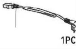
| Included Accessories | Heating plate, tray, sponge, controller, screws, key |
| Recommended Uses | T-shirts, mugs, tiles, metal sheets, caps (with accessory) |
| Maintenance and Cleaning | Clean with a damp cloth after cooling. Do not immerse. |
| Spare Parts and Repairability | Parts available through the manufacturer. Do not disassemble yourself. |
| General Information | Electronic warranty and support at www.vevor.com/support |
Frequently Asked Questions - TL-FY8001 Vevor
User questions about TL-FY8001 Vevor
0 question about this device. Answer the ones you know or ask your own.
Ask a new question about this device
Download the instructions for your Heat press in PDF format for free! Find your manual TL-FY8001 - Vevor and take your electronic device back in hand. On this page are published all the documents necessary for the use of your device. TL-FY8001 by Vevor.
USER MANUAL TL-FY8001 Vevor
Technical Support and E-Warranty Certificate www.vevor.com/support
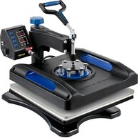
HEAT PRESS MACHINE
We continue to be committed to provide you tools with competitive price. "Save Half", "Half Price" or any other similar expressions used by us only represer estimate of savings you might benefit from buying certain tools with us compared to top brands and does not necessarily mean to cover all categories of tools offered by are kindly reminded to verify carefully when you are placing an order with us if yo actually saving half in comparison with the top major brands.
VEVOR®
TOUGH TOOLS, HALF PRICE
HEAT PRESS MACHINE
MODEL:TL-FY8001
natural_image
Technical line drawing of a mechanical device with no visible text or symbolsNEED HELP? CONTACT US!
Have product questions? Need technical support? Please feel free contact us:
Technical Support and E-Warranty Certificate www.vevor.com/support
This is the original instruction, please read all manual instructions carefully before operating. VEVOR reserves a clear interpretation of user manual. The appearance of the product shall be subject to the product you received. Please forgive us that we won't inform you there are any technology or software updates on our product.
| Symbol | Symbol Description |
 | Warning: To reduce the risk of injury, the user must read the instructions manual carefully. |
 | This symbol, placed before a safety comment, indicates a kind of precaution, warning, or danger. Ignoring this warning may lead to accident. To reduce the risk of injury, fire, or electrocution, please always follow the recommendations shown below. |
 | CORRECT DISPOSAL: This product is subject to the provision of European Directive 2012/ 19/EC. The symbol showing a wheelie bin crossed through indicates that the product requires separate refuse collection in the European Union. This applies to the product and all accessories marked with this symbol. Products marked as such may not be discarded with normal domestic waste, but must be taken to a collection point for recycling electrical and electronic devices. |
WARNING
- Warnings must be followed carefully to avoid body injury. Improper use may result in electric shock, fire, personal injury and other damage:
1) Keep unplug when moving the machine.
2) Keep unplug when installing accessories.
3) Place on a If at and stable platform and operate under ventilated conditions.
4) Wear special protective equipment when operating the machine.
5) Do not use this machine in a hazardous-location.
6) Do not use when the machine is not working properly.
7) Do not disassemble and repair this machine.
8) Do not use an unsuitable AC Outlet.
9) Do not touch the heating plate when the machine is heating
10) Do not use in humid environment or contact with water. Do not infiltrate liquid in the machine to prevent fire or electric shock caused by short circuit.
11) Do not use the power supply that does not meet the rated voltage. The power
supply that does not meet the specified voltage may cause fire or electric shock.
12) Ensure that the machine is grounded so as not to cause harm to body.
13) Do not touch the rotating rod or bearing part with y ur fingers during use in case of injuries.
14) If the machine is not in use for a long time, please unplug the power cord from the socket.
15) Do not use the machine during thunderstorms or lighting to avoid damage to the machine.
16) Place the machine smoothly on the flame-retardant table and keep away from flammable and explosive items.
17) Please stop using it if the machine smokes, emits a peculiar smell, or becomes noisy and other abnormal conditions.
18) This appliance can be used by children aged from 8 years and above and persons with reduced physical, sensory or mental capabilities or lack of experience and knowledge
if they have been given supervision or instruction concerning use of the appliance in a safe way and understand the hazards involved. Children shall not play with the appliance. Cleaning and user maintenance shall not be made by children without supervision
19) Type X attachment: If the supply cord is damaged, it must be replaced by a special cord or assembly available from the manufacturer or its service agent.
20) In order to avoid a hazard due to inadvertent resetting of the thermal cutout, this appliance must not be supplied through an external switching device, such as a timer, or connected to a circuit that is regularly switched on and off by the utility.

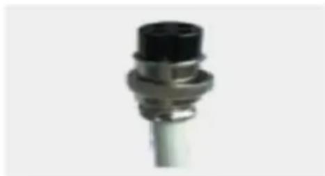
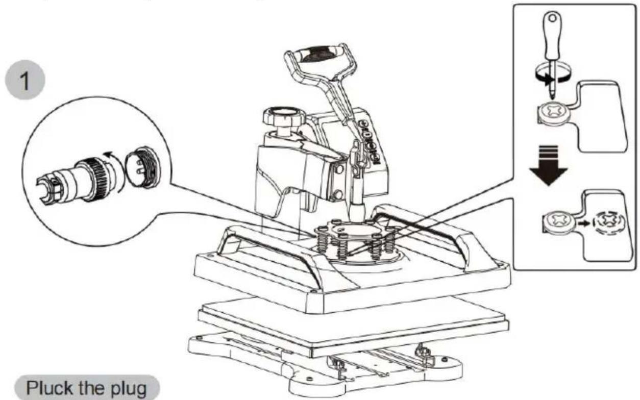
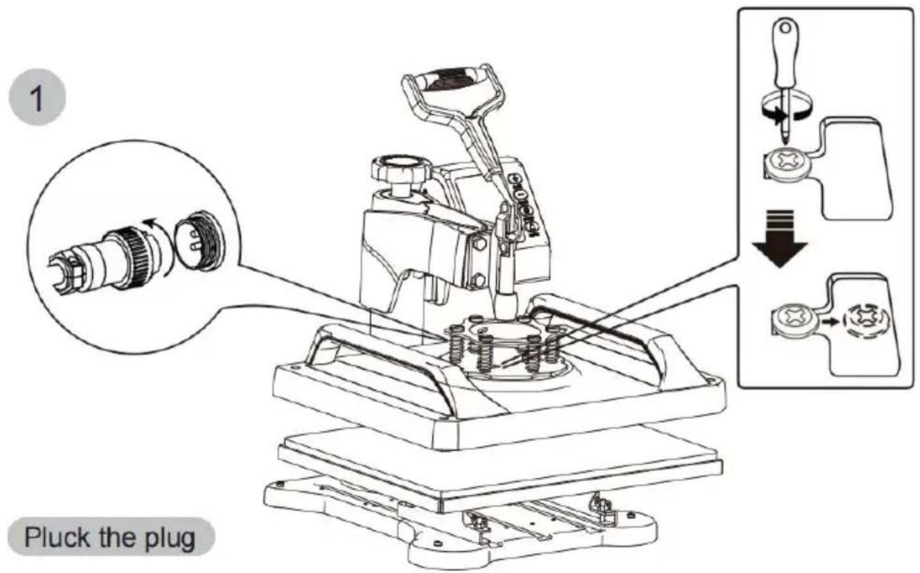
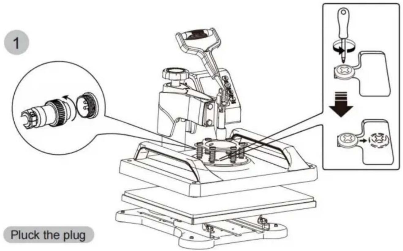
Warning
Please turn off the power when plug or unplug the connector.
natural_image
Close-up of a metallic connector with black cap and flange (no text or symbols visible)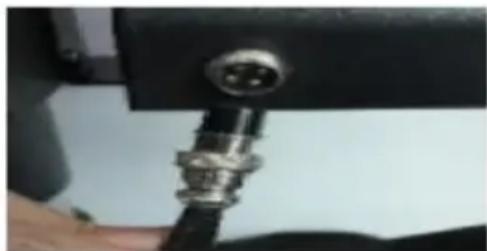
natural_image
Close-up of a metallic connector with a circular port, mounted on a black mechanical base (no visible text or symbols)FCC INFORMATION
CAU TI ON : Changes or modifications not expressly approved by the party responsible for compliance could void the user's authority to operate the equipment!
This device complies with Part 15 of the FCC Rules. Operation is subject to the following two conditions:
1) This product may cause harmful interference.
2) This product must accept any interference received, including interference that may cause undesired operation.
WAR NING : Changes or modifications to this product not expressly approved by the party responsible for compliance could void the user's authority to operate the product.
Note: This product has been tested and found to comply with the limits for a Class B digital device pursuant to Part 15 of the FCC Rules. These limits are designed to provide reasonable protection against harmful interference in a residential installation.
This product generates, uses and can radiate radio frequency energy, and if not installed and used in accordance with the instructions, may cause harmful interference to radio communications. However, there is no guarantee that interference will not occur in a particular installation. If this product does cause harmful interference to radio or television reception, which can be determined by turning the product off and on, the user is encouraged to try to correct the interference by one or more of the following measures.
- Reorient or relocate the receiving antenna.
- Increase the distance between the product and receiver.
- Connect the product to an outlet on a circuit different from that to which the receiver is connected.
- Consult the dealer or an experienced radio/TV technician for assistance.
SPECIFICATION
| Model | TL-FY5001, TL-FY8001 | |
| Heat Size | 12x15inch | |
| Temperature Range | 32-450°F(0-232°C) | |
| Time Range | 0-999 Seconds | |
| Voltage | 120V~ 60Hz | 220-240V~ 50Hz |
| Power | 900W | 1250W |
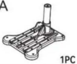
HEAT PRESS MACHINE PARTS INTRODUCTION
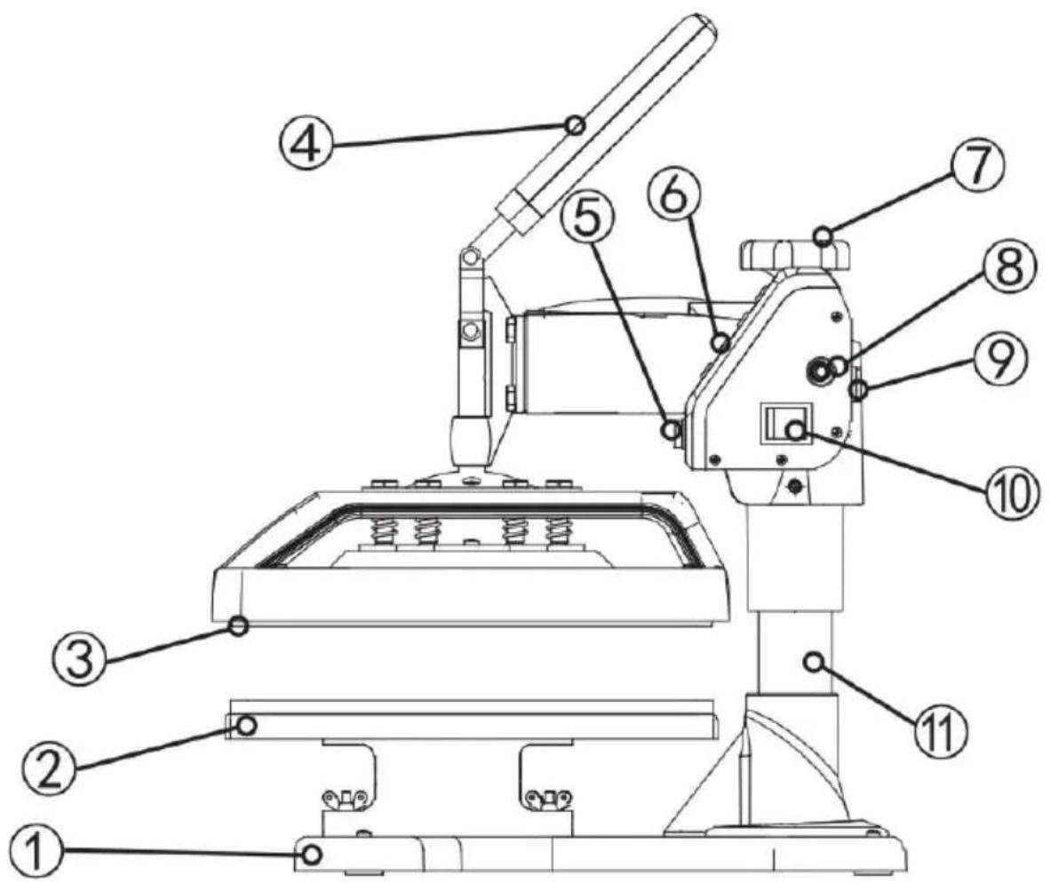
| Number | Part name | Number | Part name |
| 1 | Pedestal | 7 | Lift knob |
| 2 | Placement | 8 | Overload protector |
| 3 | Heating plate | 9 | Power socket |
| 4 | Handle | 10 | Power switch |
| 5 | Aviation connector | 11 | Column |
| 6 | Button | 12 |
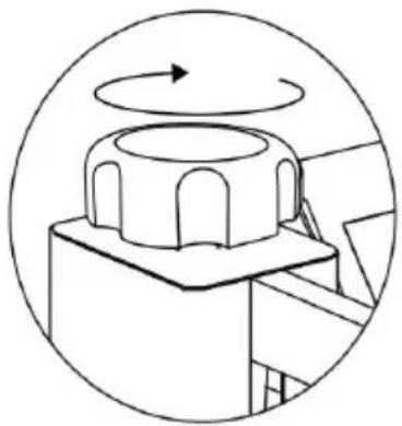
The pressure Adjustment knob controls the amount of force that will be used to push the transferred image into the fibers of the garment.
Clockwise increases pressure. Counterclockwise decreases it.
The Control Panel on the right upper face of the casing is where you will set the heat and time requirements for your project. These will vary depending on the vinyl or transfer paper used.
The handle opens & closes the top & bottom Heated Platens of the revolve press.
The overload protector is a breaker. It will pop out when there is an overload of electricity.
Press it in to reset.
The Power switch must be set to the on position and the Cord must be plugged in before pressing.
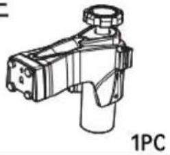
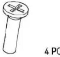
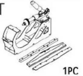
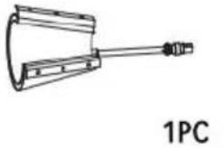
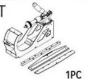
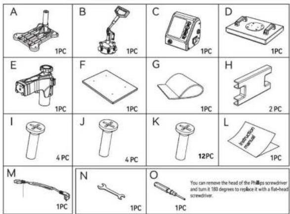
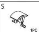
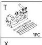
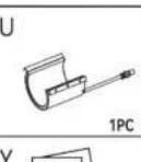
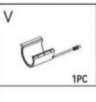
PARTS LIST
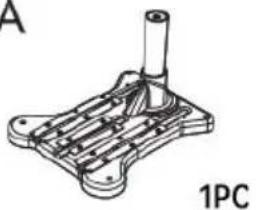 | B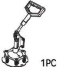 | C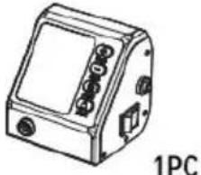 | D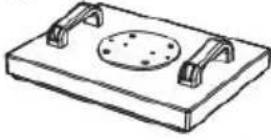 1PC 1PC |
 | F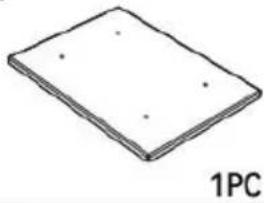 | G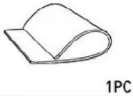 | H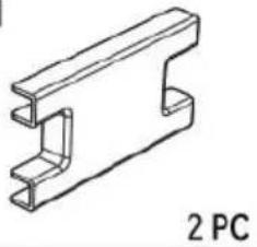 |
 | J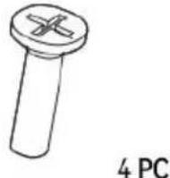 | K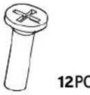 | L |
 | N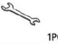 | O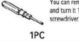 | |
P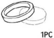 | Q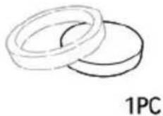 | R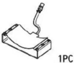 | S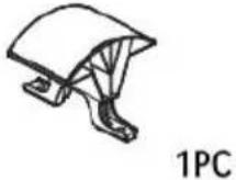 |
 | U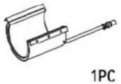 | V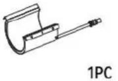 | W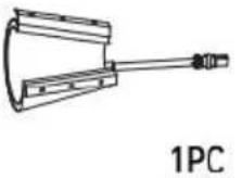 |
 | Y | ||
| Part | A | B | C | D | E | F | G | H | I | J | K | L | M |
| 5IN1 | √ | √ | √ | √ | √ | √ | √ | √ | √ | √ | √ | √ | √ |
| Part | N | O | P | Q | R | S | T | U | V | W | X | Y | |
| 5IN1 | √ | √ | √ | √ | √ | √ | √ | √ | √ |
| Part | A | B | C | D | E | F | G | H | I | J | K | L | M |
| 8IN1 | √ | √ | √ | √ | √ | √ | √ | √ | √ | √ | √ | √ | √ |
| Part | N | O | P | Q | R | S | T | U | V | W | X | Y | |
| 8IN1 | √ | √ | √ | √ | √ | √ | √ | √ | √ | √ | √ | √ |
- Turn the pressure knob counterclockwise a few times to lower pressure on the platens.
- Place a piece of paper onto bottom of the platen.
- Close the revolve press using the handle.
4.Pull on the paper. - If the paper moves at all, turn the knob clockwise and try again.
- Try again and repeat until the paper doesn't move at all. This is your "Medium" pressure.
From the “Medium” setting, high pressure will be Clockwise one to two turns. Low pressure will be counterclockwise one to two turns. (The number of turns will depend on the thickness of the garment).
SETTING TEMPERATURE & TIME

PLUS

MINUS

SETUP

START
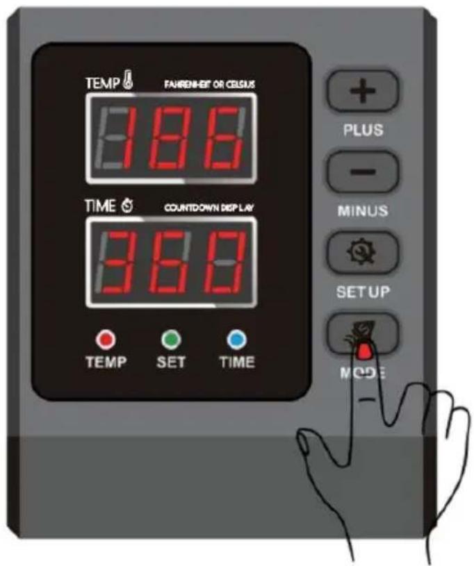
- How to turn on/off and how to start?
Press the switch button on the side of the temperature control box to turn it on.
Countdown start button, press once to start the countdown; press again to reset.
- How to set the temperature/time?
Press once to set the temperature, press twice to set the time and press again to exit. (It will automatically exit the temperature/time setup state in case of no operation within 5sec.).
- How to set the temperature/time to increase or decrease?
+ Set the time/temperature increase
- Set the time/temperature decrease
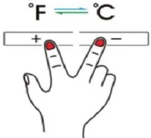
- How to change the temperature unit from ^ C to ^ F?
In the power-on state, press "+" and "-" at the same time to change the temperature unit between ^ C and ^ F .
- Tips: The max. set temperature of this machine is 232^ C and the longest time is 999sec.
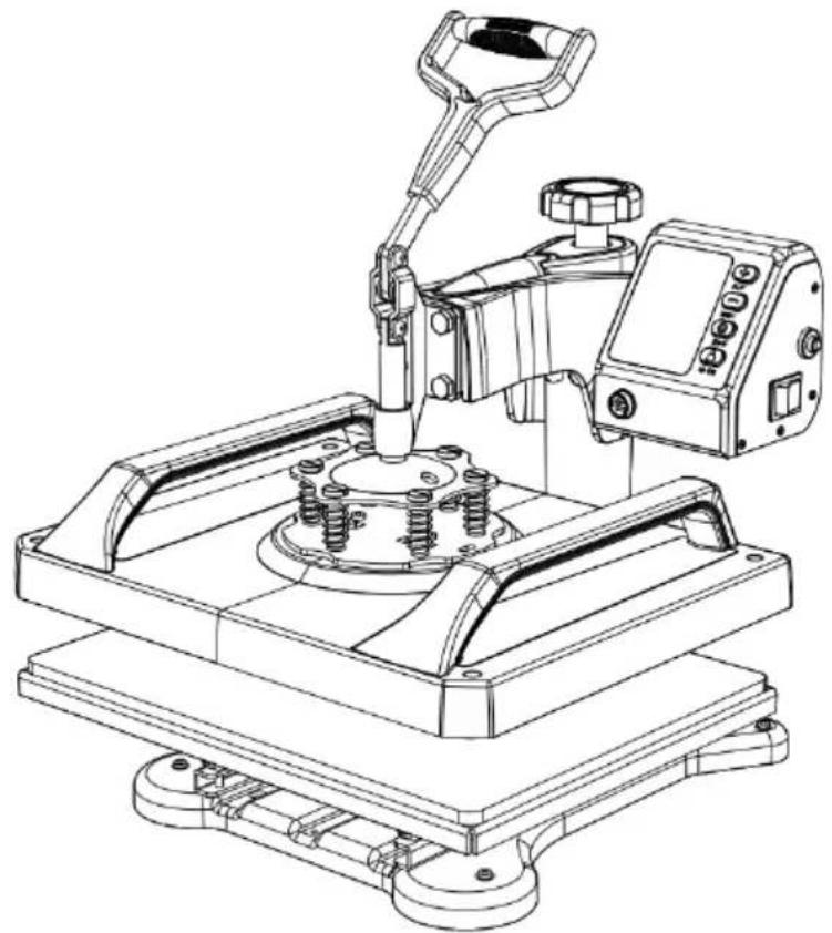
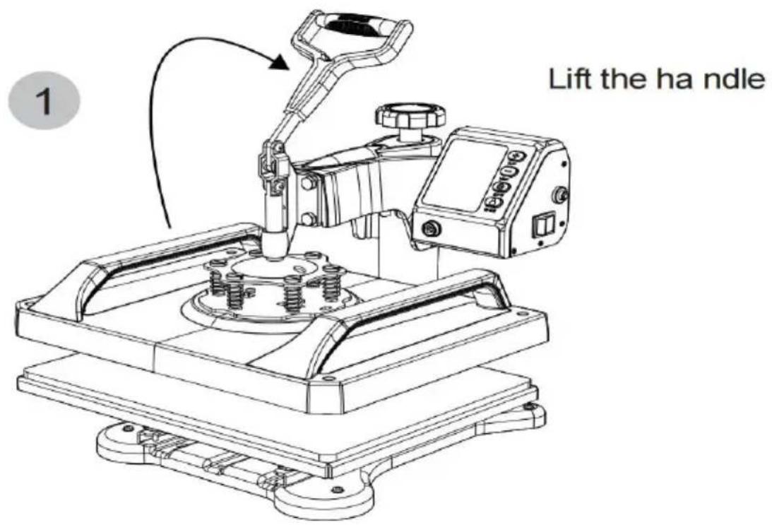
Assembly and Disassembly of the Machine
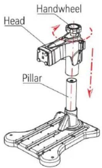
Fig 1
-
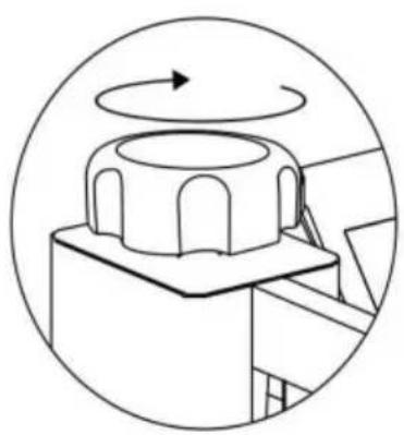
Put the head into the pillar and rotate the handwheel 10 times clockwise, which indicates that the head is installed (as shown in fig1).
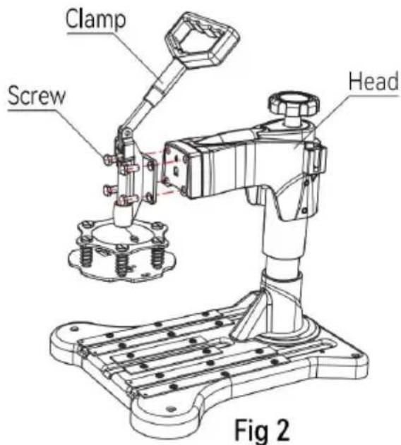
-
Pass the four screws through the quick clip and adapter, then screw them securely to the machine head and use a wrench to lock the screws (as shown in figure2).
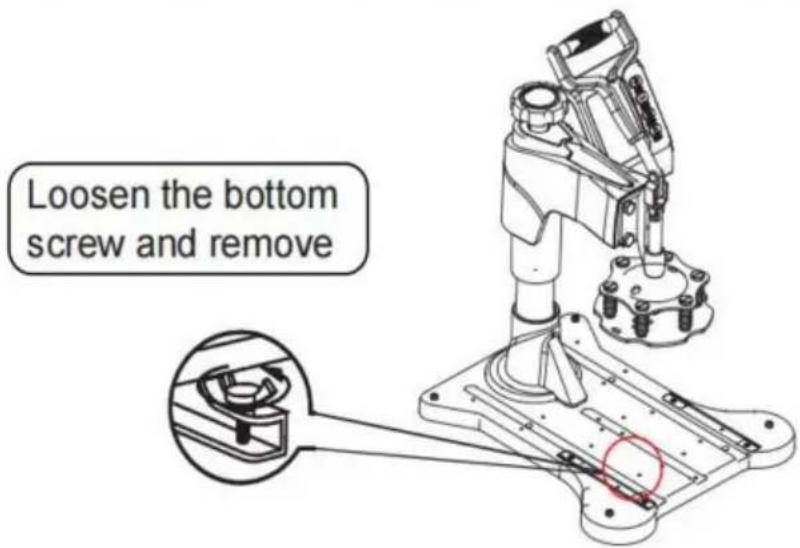
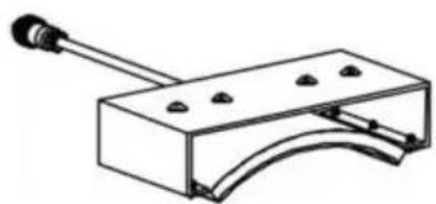
- Use 4 screws from the bottom up, through the bearing bar from the back of the backplane, and then lockit with hand screws (as shown in figure3).
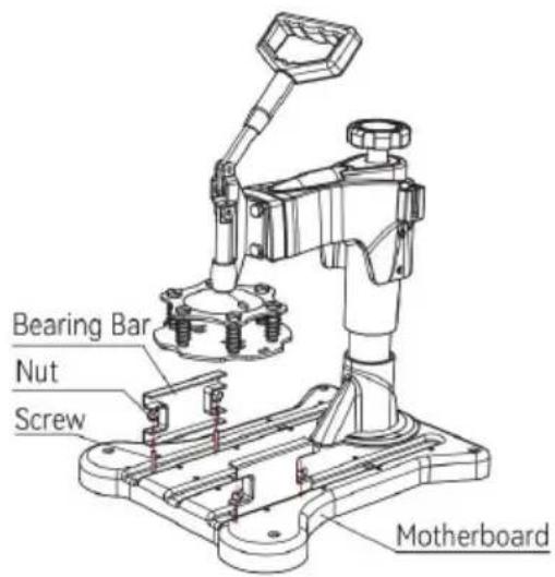
Fig 3
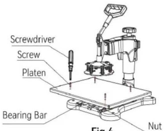
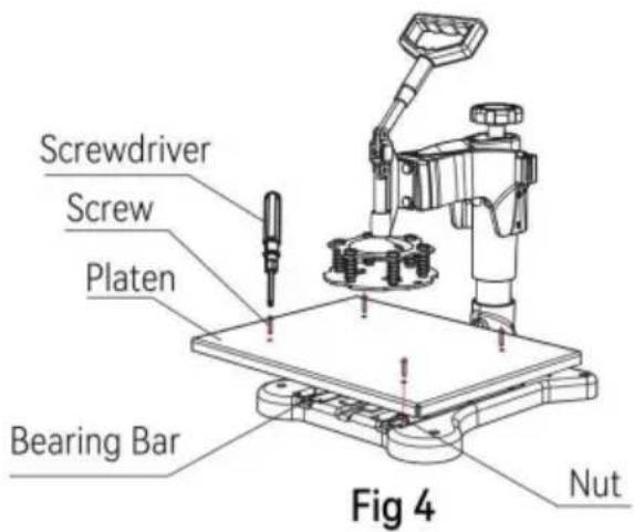
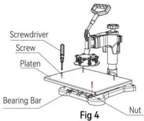
Fig 4
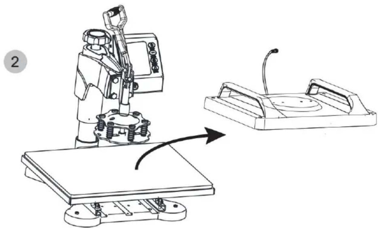
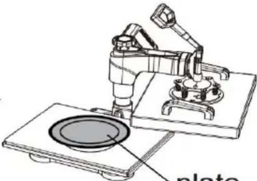
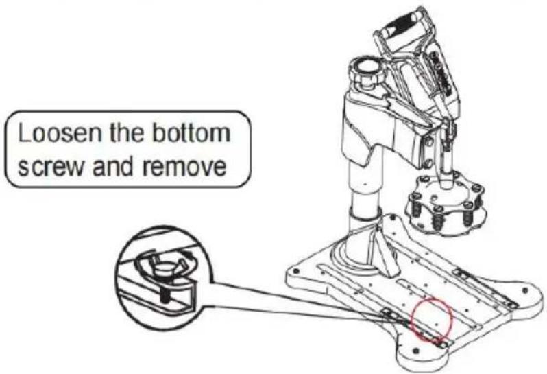
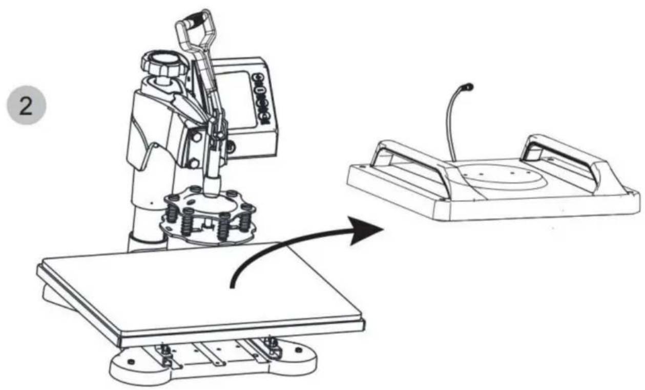
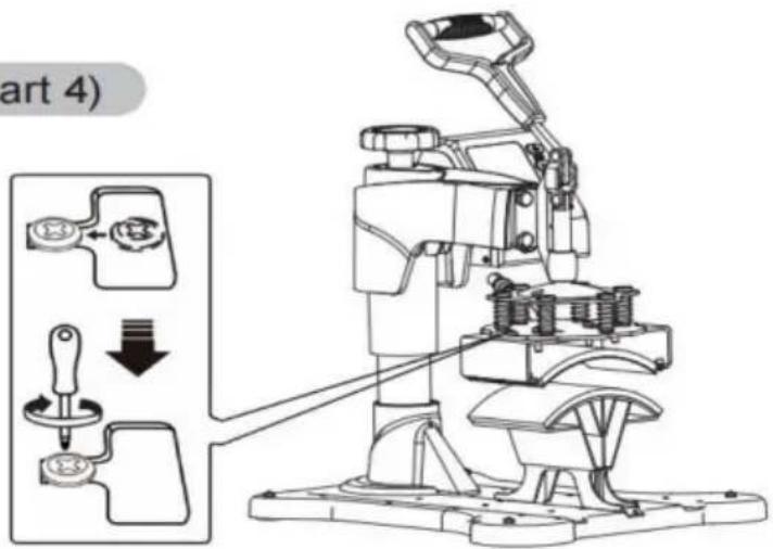
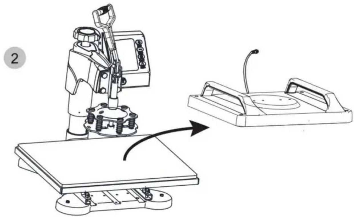
- Place the table platen flat on the bearing bar, align the platen with the hole in the bearing bar, place the screw, and lock it with a screwdriver (as shown in figure4).
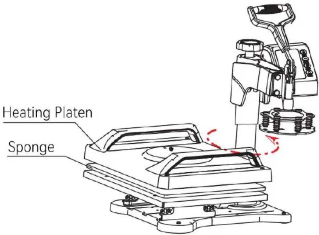
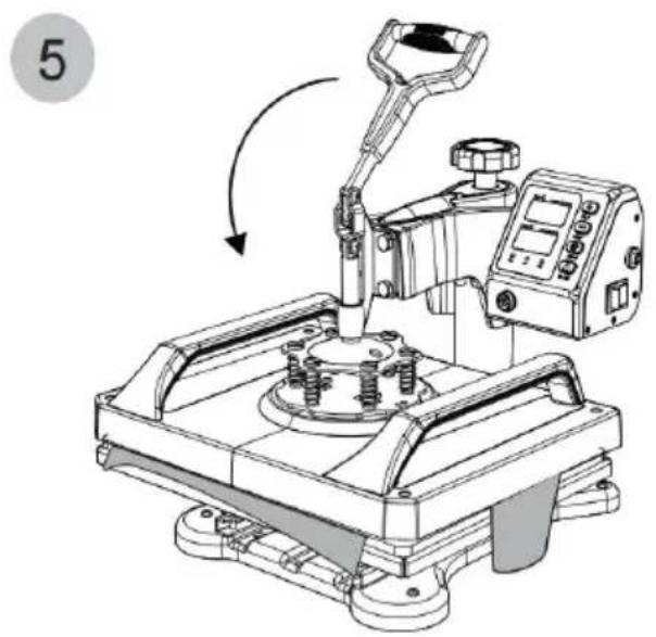
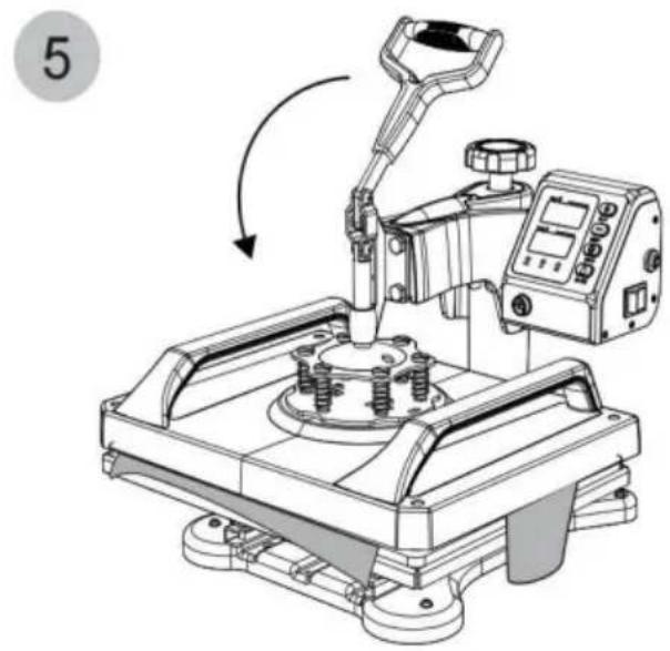
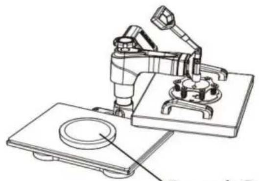
Fig 5
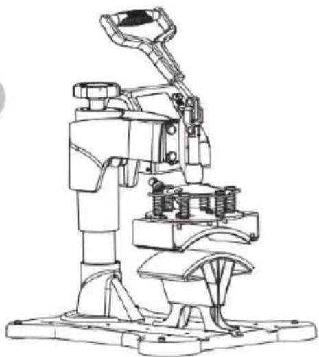
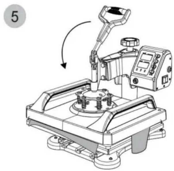
- Swing the head away and put the sponge and the heating platen on the top of the table platen in order.(as shown in figure5)
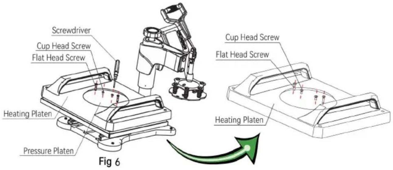
- Place the pressure platen flat on the heating platen, align it with the hole. Take 4 fat head screws and tighten them with a screwdriver.
Take 2 cup head screws and lock them to the hole in the middle of the pressure platen. At this time, do not lock the cup head screws: reserve 5-7mm for the next installation step (as shown in figure6).
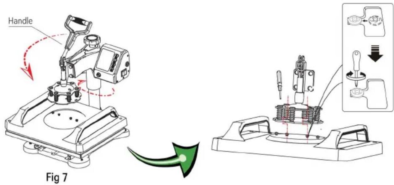
- Rotate the head back to the original position and gently press down the handle so that the cup cap of the cup head screw above the pressure platen snaps into the slot and then lock it in place with a screwdriver (as shown in fig7)
natural_image
Technical line drawing of a mechanical device with red motion arrows indicating rotation or movement (no text or symbols)Fig 8

natural_image
Technical line drawing of a mechanical assembly with a magnified inset showing a connector detail (no text or symbols)Fig 9
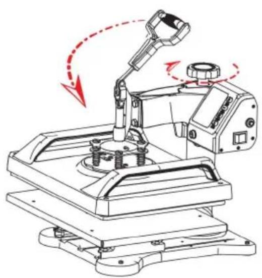
- Rotate the handwheel and try to press the handle several times until it is adjusted to the appropriate pressure(as shown in figure8).
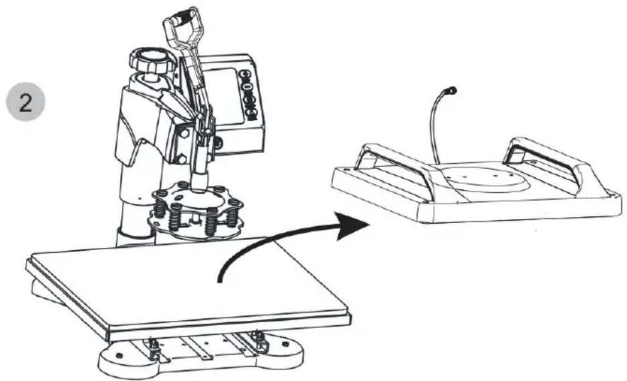
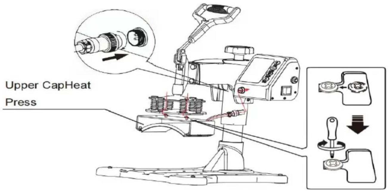
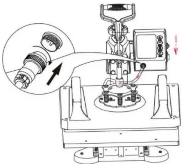
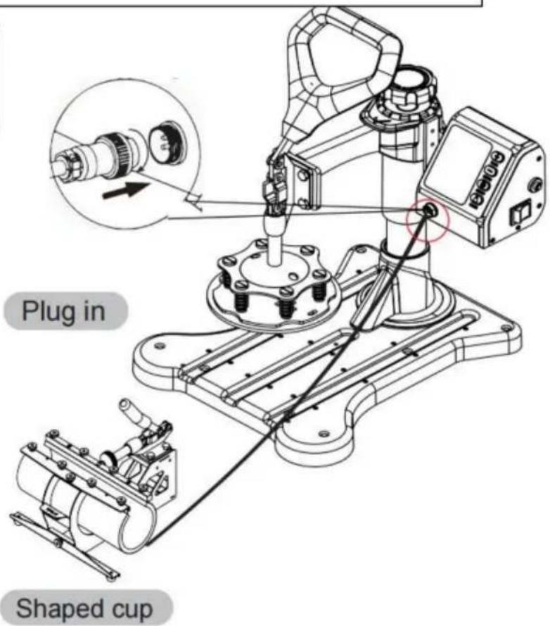
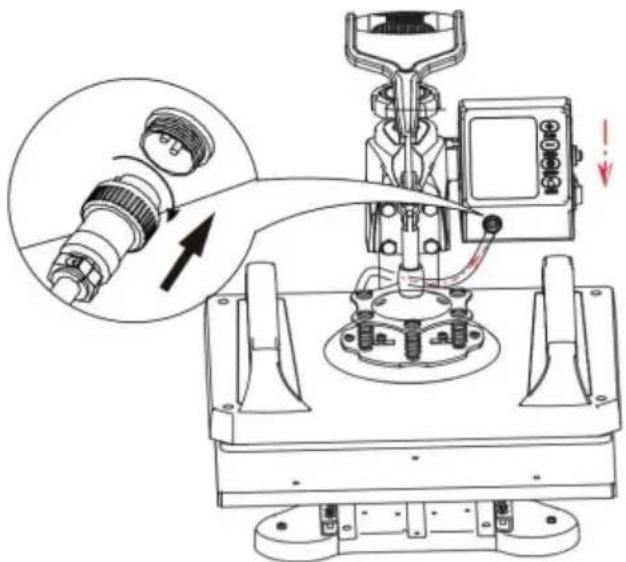
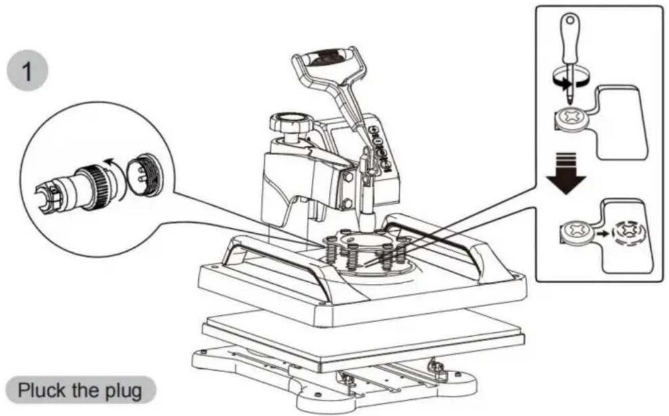
- Clip the controller into the head slot from top to bottom, connect the male head of the heating platen with the female head of the control
controller, and lock the nut to complete the installation (as shown in figure 9).
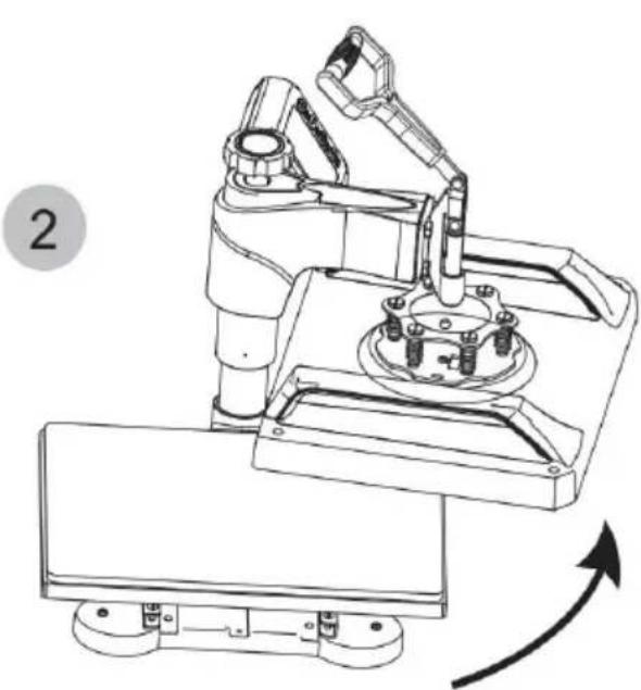
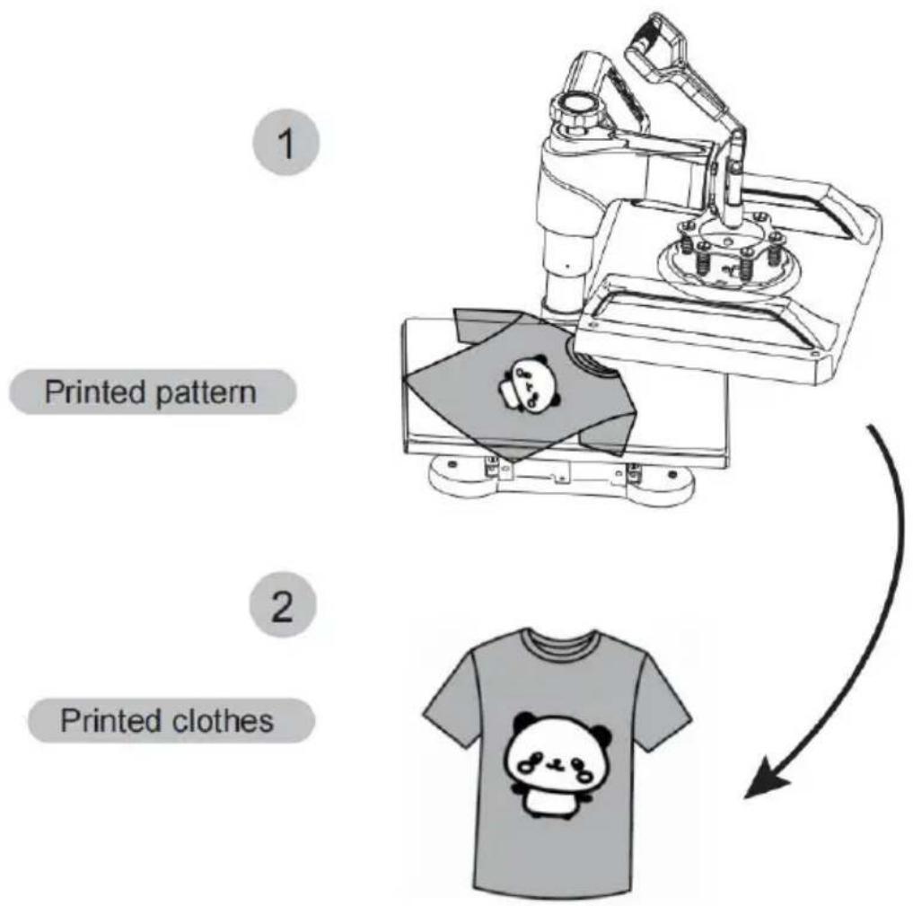
How to press T-shirts
natural_image
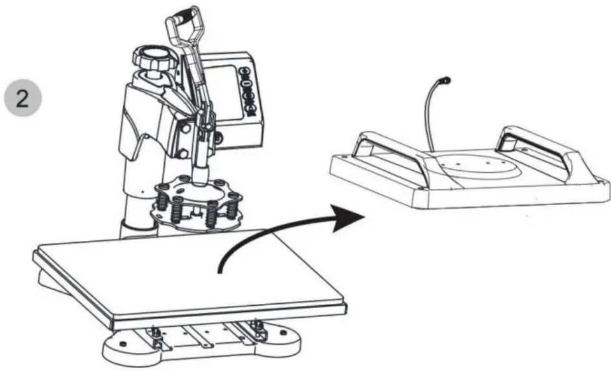
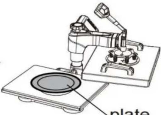
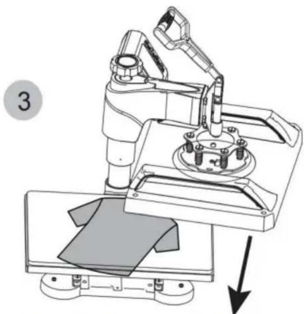
Technical line drawing of a robotic arm with articulated joints and mounting base (no text or symbols)Rotate the heating platen to one side
natural_image
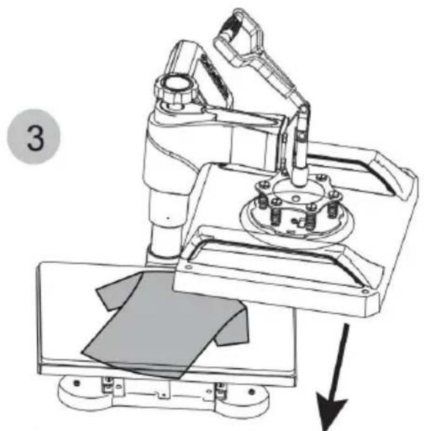
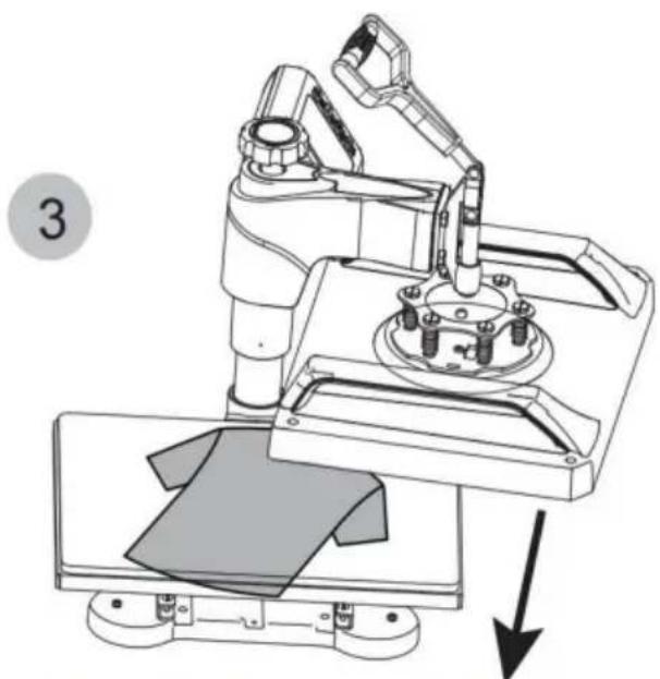
Technical line drawing of a robotic arm with a mechanical base and mounting bracket, showing a downward force arrow (no text or symbols present)Pull out the lower panel, place the clothes flat on the platen, and place the pattern on the clothes.
4
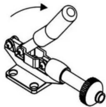
natural_image
Technical diagram of a mechanical component with rotational arrow, no visible text or symbolsRotate this switch to adjust pressure
natural_image
Technical line drawing of a mechanical device with a lever and control panel (no text or symbols)I. Preparation before Using:
- Check the connection between the power plug and the electrical socket of the electrical cabinet.
Be sure to operate with safe ground wire!!!
- Heat press element must be securely plugged into the machine before you switch the machine on. Plug your electrical cord into the machine. Plug electrical socket into wall plug. Turn the power on by flipping the on/off Switch on.
II. Set temperature required
Set the temperature and time according to the table below and get the Specific corresponding temperature and timing setting.(Temperature is Measured in Degrees Fahrenheit.)
| Press Object | Initial Temperature | Highest Temperature | Proper Heating Time(s) |
| Mugs | 230 | 330 | 40 |
| Tiles | 230 | 330 | 40 |
| Metal board | 230 | 330 | 40 |
| Plate | 230 | 355 | 150 |
| T-shirt | 230 | 355 | Sublimation paper:30-50s |
| T-shirt Paper:10-20s |
A. Initial Temperature Setting(Range:200-450F)
Press the "MODE" button ONCE, and see the "set light" turning red. Then press the "plus/minus key" to set the initial heating temperature.
B.Highest Temperature Setting(Range:93-232C)
Press the "MODE" button for THE SECOND TIME; see the "temperature light" turning red. Then press the "plus or minus key" set the highest Heating temperature.
C. Proper Heating Time Setting (Range: 0-999sec.)
Press the "MODE" button for THE THIRD TIME; see the "time light turning red. Then press the"plus or minus key"to set the proper heating time.
After turning on the hot stamping machine, press the + and - buttc Simultaneously for about five seconds. When PAE is displayed, press the MODE key to display(F-C), and change F to C in the tir display gear, so that Fahrenheit is converted to Celsius.
E. Finish the Setting and Stand by to Work
Press the "MODE" button for THE FOURTH TIME; finish the setting. The set light is on, and the temperature will continue to rise. When the set Maximum temperature is reached, the countdown starts.
After the countdown ends, the "BEEF" sound will be emitted, the
indicator light will turnoff, and the operation is complete. And the machine stands by to work.

Turn off the power and pull out the mat. It is recommended to wear heat-resistant gloves when removing clothes or remove them after 2-3 minutes. Be careful of hot heat.
Note
The machine has a self-locking function for temperature setting. ---If the starting temperature is set to 340^ , the machine will automatically limit the maximum temperature setting range from 340 to 430^
---Conversely, if setting the maximum temperature is 250^ F at first, the machine will automatically limit the starting temperature setting range from 200 to 250^ F.
Initial heating temperature always=<Highest heating temperature
Use a Phillips screwdriver to unscrew the screws in the two holes the pressure plate to replace the accessories.
natural_image
Technical line drawing of a robotic machine with a control panel and a close-up view of its mechanical component (no text or symbols)Rotate the heat transfer board to the side
3
natural_image
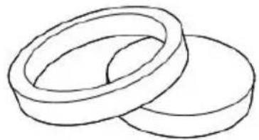
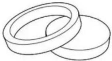
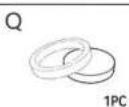
Simple line drawing of two overlapping rings (no text or symbols)Choose the right size Plate Press.
combination
separate
4
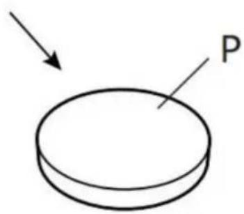
natural_image
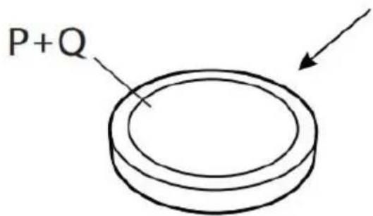
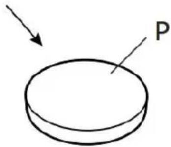
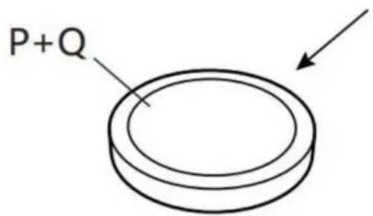
Technical line drawing of a mechanical device with a cylindrical component and base plate (no text or symbols)P and Q
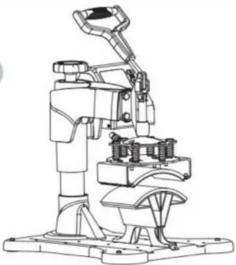
natural_image
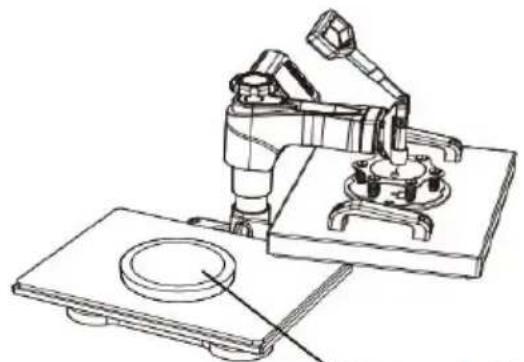
Technical line drawing of a robotic arm operating on a plate (no text or symbols)plate

natural_image
Cute cartoon panda inside a circular frame with stars (no text or symbols)Patterned plate
natural_image
Technical line drawing of a robotic machine with a control panel and a close-up view of its mechanical component (no text or symbols)Rotate the heat transfer board to the side
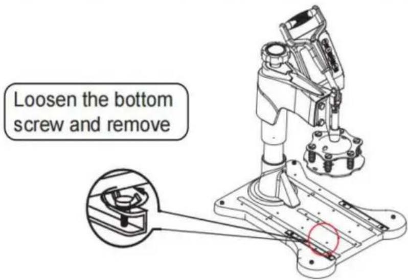
3 Unscrew the four butterfil screws.at bottom
4
natural_image
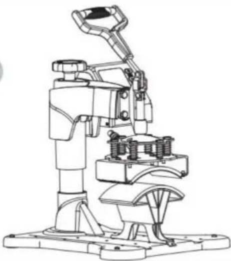
Technical line drawing of a mechanical device with no visible text or symbolsLift the cushion up
5

natural_image
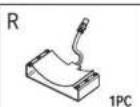
Technical line drawing of a mechanical clamp or bracket with mounting holes (no text or symbols)Install the backing pad (part 4)
6
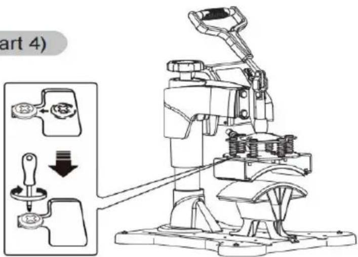
Use the screwdriver 4 to tighten the 2 screws just removed and put the cap on
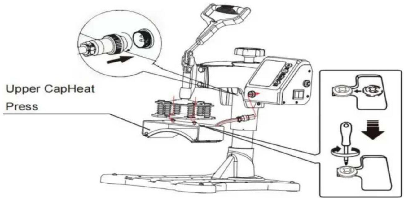
- Take 2 cup head screws and lock them into the hole in the mid of the cap press. Do not lock the cup head screws, leave 5-7mm, the clip the cup head screw into the slot along the indicated route and lock it with a screwdriver. Insert the male head of the cap press p into the female head of the controller and tighten nut.

Install H to Part T.
(Tighten the screws on both sides.We suggest to tighten the screws
the ① side first, and then tighten the screws on the ② side)
natural_image
Mechanical assembly diagram showing a lever mechanism with no text or symbols
TROUBLE SHOOTING FOR TRANSFER QUALITY
- Light Color or Faded Image: Insufficient Temperature / Incorrect pressure / Insufficient Time.
- Fuzzy Image: pressing time is too long.
- Part of the pattern Blurred: The heat is not being distributed correctly through the heating plate, so the working time can be increased appropriately. It may also be the cause of uneven pressure distribution, which can be set on four board regulators. Please note that the four board regulators have been set up before they leave the factory and should not need to be adjusted normally.
- Dim Pattern: Too much pressure or temperature.
- Scarred Pattern: Transfer time is too long.
- Different Pattern Colors: Incorrect pressure or poor quality of transfer paper.
- Scorched Pattern: High temperature or poor ink.
Manufacturer:Shanghaimuxinmuyeyouxiangongsi
Address: Shuangchenglu 803nong11hao1602A-1609shi, baoshanqu, shanghai 200000 CN.
Imported to AUS: SIHAO PTY LTD. 1 ROKEVA STREETEASTWOOD NSW 2122 Australia
Imported to USA: Sanven Technology Ltd. Suite 250, 9166 Anaheim Place, Rancho Cucamonga, CA 91730
| EC | REP |
E-CrossStu GmbH
Mainzer Landstr.69, 60329 Frankfurt am Main.
| UK | REP |
YH CONSULTING LIMITED.
C/O YH Consulting Limited Office 147, Centurion House,
London Road, Staines-upon-Thames, Surrey, TW18 4AX
VEVOR®
TOUGH TOOLS, HALF PRICE
Technical Support and E-Warranty Certificate www.vevor.com/support
VEVOR®
TOUGH TOOLS, HALF PRICE
natural_image
Technical line drawing of a mechanical device with a lever and base platform (no text or symbols)natural_image
Close-up of a metallic connector with black cap and flange (no text or symbols visible)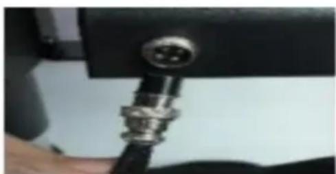
natural_image
Close-up of a metallic connector with a circular port, mounted on a black surface (no visible text or symbols)INFORMAZIONI FCC
 | B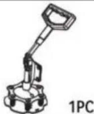 | C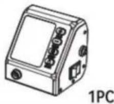 | D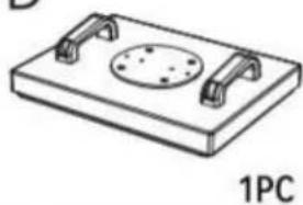 |
F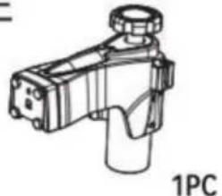 | F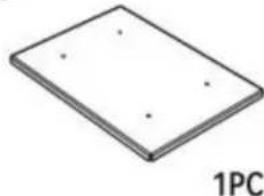 | G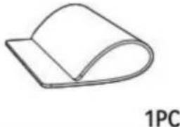 | H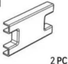 |
I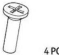 | J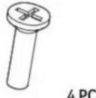 | K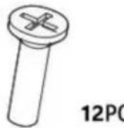 | L |
M | N c c | Onove the head of the Phillips screwdriver180 degrees to replace it with a flat-head | |
P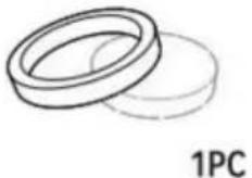 | Q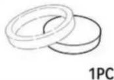 | R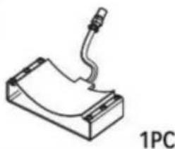 | S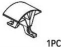 |
 | U | V | W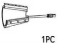 |
X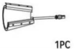 | Y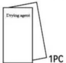 | ||
COME CALIBRARE LA TUA NUOVA PRESSA A CALDO
Fig 1

Fig 3
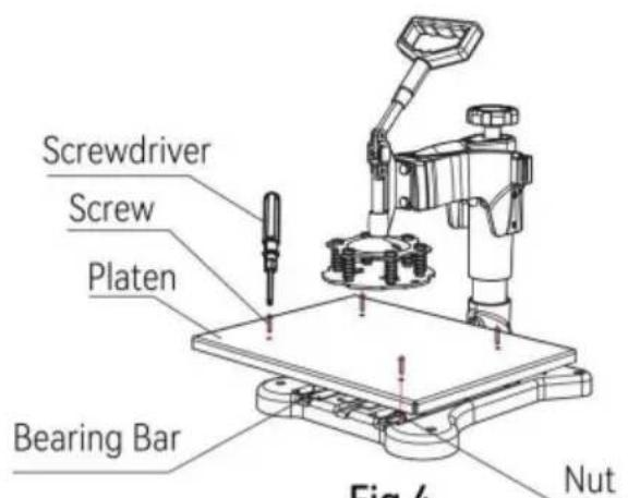
Fig 4
natural_image
Technical line drawing of a mechanical device with red motion arrows indicating rotational movement (no text or symbols)Fig 8
natural_image
Technical diagram of a mechanical assembly with a magnified inset showing a connector and directional arrows (no text or symbols)Fig 9
natural_image
Technical line drawing of a robotic arm with rotating base and mounting base (no text or symbols)Rotate the heating platen to one side
natural_image
Technical line drawing of a robotic arm with a base and mounting base, showing mechanical components and a downward arrow indicating motion (no text or symbols present)Pull out the lower panel, place the clothes flat on the platen, and place the pattern on the clothes.
4

natural_image
Diagram of a mechanical component with a rotating arrow, enclosed in a circular frame (no text or symbols)Rotate this switch to adjust pressure

natural_image
Technical line drawing of a mechanical device with a control panel and digital display (no text or symbols)
Turn off the power and pull out the mat. It is recommended to wear heat-resistant gloves when removing clothes or remove them after 2-3 minutes. Be careful of hot heat.
Nota
natural_image
Technical line drawing of a robotic machine with a control panel and a close-up view of its base (no text or symbols)Rotate the heat transfer board to the side
3

natural_image
Simple line drawing of two overlapping rings (no text or symbols)Choose the right size Plate Press.
combination

separate
4

natural_image
Technical line drawing of a robotic arm and base platform assembly (no text or symbols)P and Q


natural_image
Technical illustration of a robotic arm operating on a plate (no text or symbols present)plate

natural_image
Cute cartoon panda inside concentric circles with stars (no text or symbols)Patterned plate
SOSTITUIRE IL TAPPETINO DELLA TEGLIA DA COTTURA

natural_image
Technical line drawing of a robotic machine with a control panel and a close-up view of its mechanical component (no text or symbols present)Rotate the heat transfer board to the side
3 Unscrew the four butterfil screws.at bottom
4

natural_image
Technical line drawing of a mechanical device with no visible text or symbolsLift the cushion up
5

natural_image
Simple line drawing of a mechanical clamp or bracket with a handle and mounting holes (no text or symbols)Install the backing pad (part 4)
6

Use the screwdriver 4 to tighten the 2 screws just removed and put the cap on

natural_image
Technical line drawing of a mechanical assembly with no visible text or symbolsImportato in AUS: SIHAO PTY LTD. 1 ROKEVA STREETEASTWOOD
Nuovo Galles del Sud 2122 Australia
natural_image
Technical line drawing of a mechanical device with a lever and base platform (no text or symbols)POTRZEBUJESZ POMOCY? SKONTAKTUJ SIĘ Z NAMI!
natural_image
Close-up of a metallic connector with black cap and flange (no text or symbols visible)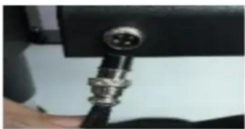
natural_image
Close-up of a metallic connector with a circular port, mounted on a black surface (no visible text or symbols)INFORMACJE FCC
| B | C | D |
| F | F | G | H  |
| I | J | K | L |
M 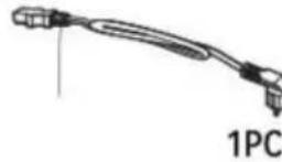 | N | O 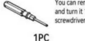 | nove the head of the Phillips screwdriver 180 degrees to replace it with a flat-head |
| P | Q | R 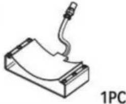 | S 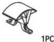 |
 | U 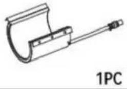 | V 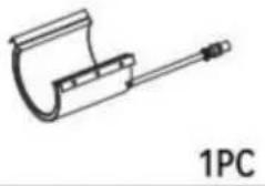 | W 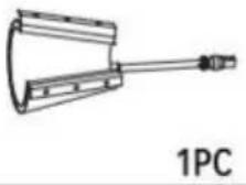 |
| X | Y | ||
JAK SKALIBROWAĆ NOWA PRASA TERMICZNA
Fig 1

Fig 3
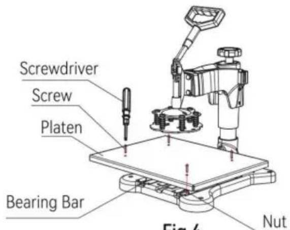
Fig 4
natural_image
Technical line drawing of a mechanical device with no visible text or symbolsFig 8

natural_image
Technical diagram of a mechanical assembly with a magnified inset showing a connector and directional arrows (no text or symbols)Fig 9
natural_image
Technical line drawing of a robotic arm with rotating base and mounting base (no text or symbols)Rotate the heating platen to one side

natural_image
Technical illustration of a robotic arm with mechanical components and a downward arrow indicating motion (no text or symbols)Pull out the lower panel, place the clothes flat on the platen, and place the pattern on the clothes.
4
natural_image
Diagram of a mechanical component with a rotating arrow, enclosed in a circular frame (no text or symbols)Rotate this switch to adjust pressure
natural_image
Technical line drawing of a mechanical device with a rotating arm and control panel (no text or symbols)INTELIGENTNY SPOSÓB DZIAŁANIA REGULATORA TEMPERATURY

Turn off the power and pull out the mat. It is recommended to wear heat-resistant gloves when removing clothes or remove them after 2-3 minutes. Be careful of hot heat.
natural_image
Technical line drawing of a robotic machine with a control panel and a close-up view of its mechanical component (no text or symbols)Rotate the heat transfer board to the side
3
natural_image
Simple line drawing of two overlapping rings (no text or symbols)Choose the right size Plate Press.

combination

separate
4

natural_image
Technical line drawing of a robotic arm and base platform assembly (no text or symbols)P and Q


natural_image
Technical illustration of a robotic arm operating on a plate with a circular base (no text or symbols)plate

natural_image
Cute cartoon panda inside concentric circles with stars (no text or symbols)Patterned plate
WYMIANA PODKŁADKI DO PIECZENIA


natural_image
Technical line drawing of a robotic machine with a control panel and a close-up view of its mechanical component (no text or symbols present)Rotate the heat transfer board to the side
WYMIANA MATY DO PIECZENIA
3 Unscrew the four butterfil screws.at bottom

4

natural_image
Technical line drawing of a mechanical device with no visible text or symbolsLift the cushion up
5

natural_image
Simple line drawing of a mechanical clamp or bracket with a handle and mounting holes (no text or symbols)Install the backing pad (part 4)
6

Use the screwdriver 4 to tighten the 2 screws just removed and put the cap on

natural_image
Technical line drawing of a mechanical assembly with no visible text or symbolsROZWIAZYWANIE PROBLEMÓW Z JAKOŚCIĄ TRANSFERU
C/O YH Consulting Limited Biuro 147, Centurion House, London Road, Staines-upon-Thames, Surrey, TW18 4AX
VEVOR®
TOUGH TOOLS, HALF PRICE
natural_image
Technical line drawing of a mechanical device with a lever and base platform (no text or symbols)natural_image
Close-up of a metallic connector with black cap and flange (no text or symbols visible)
natural_image
Close-up of a metallic connector with a circular port, mounted on a black surface (no visible text or symbols)FCC-INFORMATIONEN
| B | C | D |
F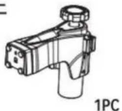 | F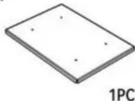 | G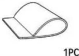 | H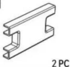 |
| I | J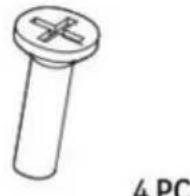 | K | L |
| M | Nc | O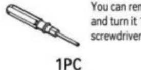 | nove the head of the Phillips screwdriver180 degrees to replace it with a flat-head |
P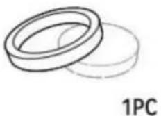 | Q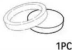 | R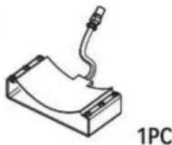 | S |
 | U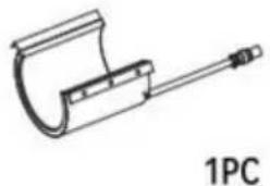 | V | W |
| X | Y | ||
SO KALIBRIEREN SIE IHRE NEUE TRANSFERPRESSE
| Teil | ABCDE | JKLM | FGHI | ||||||||||
| ÿ | ÿ | ÿ | ÿ | ÿ | ÿ | ÿ | ÿ | ÿ5IN | 1ÿÿ | ÿ | ÿ | ||
| Teil | NOPQRS | TÜVWXY | |||||||||||
| 5IN1 | ÿÿÿÿ | ÿ | ÿ | ÿÿ | ÿ |
| Teil ABCDEFGHI | JKLM | ||||||||||
| ÿ | ÿ | ÿ | ÿÿ | ÿÿ | ÿ | ÿÿ8INÿÿ | |||||
| Teil NOPQRSTUVWXY | |||||||||||
| 8IN1 | ÿÿÿ | ÿÿÿ | ÿÿ | ÿ | ÿ | ÿ | ÿ | ||||
Fig 1

Fig 3
natural_image
Technical line drawing of a mechanical device with red motion arrows indicating rotational movement (no text or symbols)Fig 8

natural_image
Technical diagram of a mechanical assembly with a magnified inset showing a component being inserted (no text or symbols present)Fig 9
natural_image
Technical line drawing of a robotic arm with rotating base and mounting base (no text or symbols)Rotate the heating platen to one side

natural_image
Technical line drawing of a robotic arm with a base and mounting base, showing mechanical components and a downward arrow indicating motion (no text or symbols present)Pull out the lower panel, place the clothes flat on the platen, and place the pattern on the clothes.
4

natural_image
Diagram of a mechanical component with a rotating arrow, enclosed in a circular frame (no text or symbols)Rotate this switch to adjust pressure

natural_image
Technical line drawing of a mechanical device with a control panel and digital display (no text or symbols)FUNKTIONSMETHODE DES INTELLIGENTEN TEMPERATURREGLERS

Turn off the power and pull out the mat. It is recommended to wear heat-resistant gloves when removing clothes or remove them after 2-3 minutes. Be careful of hot heat.

natural_image
Technical line drawing of a robotic machine with a control panel and a close-up view of its mechanical component (no text or symbols)Rotate the heat transfer board to the side
3

natural_image
Simple line drawing of two overlapping rings (no text or symbols)Choose the right size Plate Press.

combination

separate
4

natural_image
Technical line drawing of a robotic arm and base platform assembly (no text or symbols)P and Q
natural_image
Technical illustration of a robotic arm operating on a plate with a circular base (no text or symbols)plate

natural_image
Cute cartoon panda inside concentric circles with stars (no text or symbols)Patterned plate

natural_image
Technical line drawing of a robotic machine with a control panel and a close-up view of its mechanical component (no text or symbols)Rotate the heat transfer board to the side
3 Unscrew the four butterfil screws.at bottom

4
natural_image
Technical line drawing of a mechanical device with no visible text or symbolsLift the cushion up
5

natural_image
Simple line drawing of a mechanical clamp or bracket with a handle and mounting holes (no text or symbols)Install the backing pad (part 4)
6

Use the screwdriver 4 to tighten the 2 screws just removed and put the cap on

natural_image
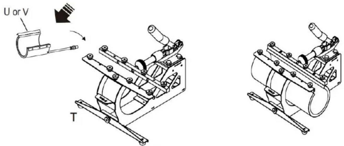
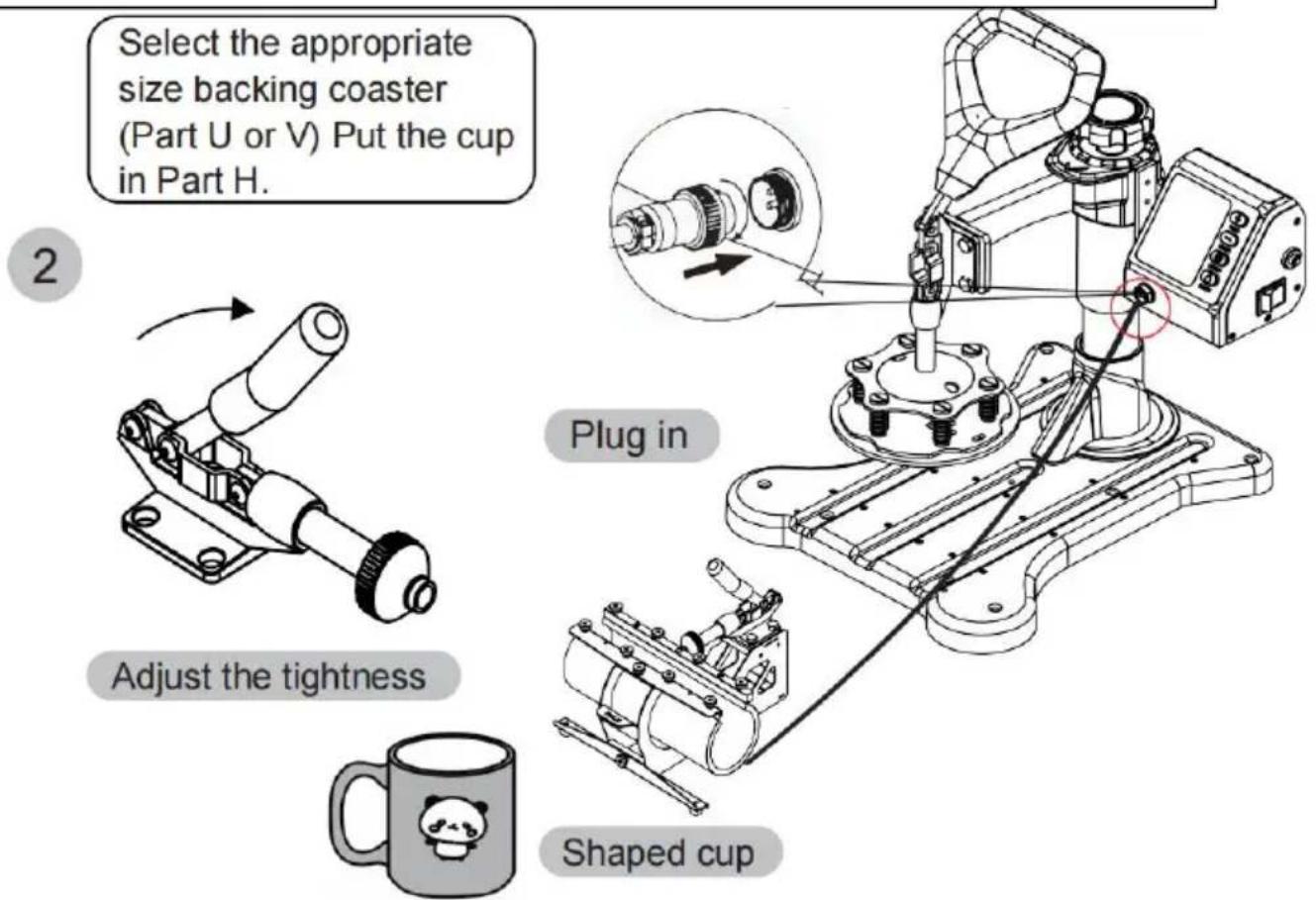
Technical line drawing of a mechanical assembly with no visible text or symbolsSelect the appropriate size backing coaster (Part U or V) Put the cup in Part H.
2
natural_image
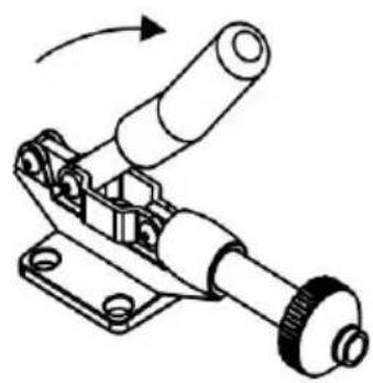
Mechanical assembly diagram showing a lever mechanism with no visible text or symbolsAdjust the tightness


C/O YH Consulting Limited Office 147, Centurion House, London Road, Staines-upon-Thames, Surrey, TW18 4AX
VEVOR®
TOUGH TOOLS, HALF PRICE
natural_image
Technical line drawing of a mechanical device with a lever and base platform (no text or symbols)BESOIN D'AIDE? CONTACTEZ-NOUS!
natural_image
Close-up of a metallic connector with black cap and flange (no text or symbols visible)
natural_image
Close-up of a metallic connector with a circular port, mounted on a black surface (no visible text or symbols)INFORMATIONS FCC
| B | C | D |
| F | F | G | H |
| I | J | K | L |
| M | N | O | nove the head of the Phillips screwdriver 180 degrees to replace it with a flat-head |
| P | Q | R | S |
| U | V 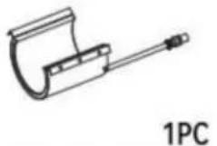 | W 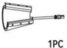 |
| X | Y | ||
COMMENT CALIBRER VOTRE NOUVELLE PRESSE À CHAUD
Fig 1
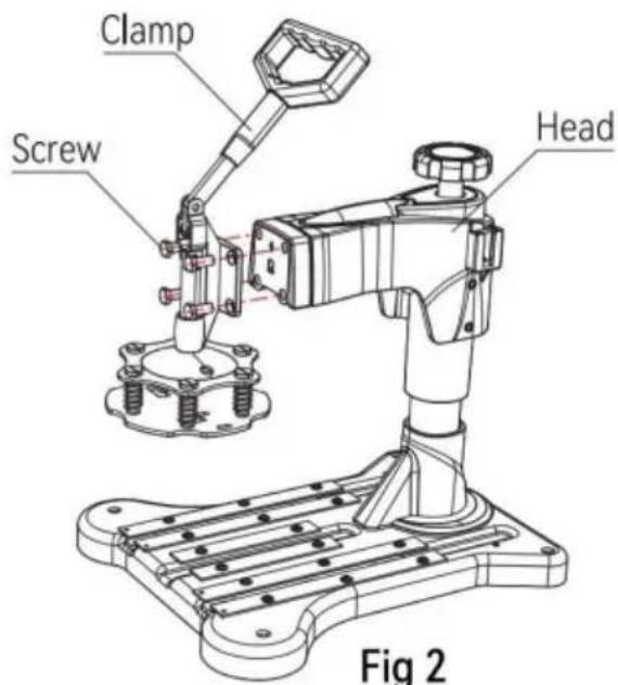
Fig 3
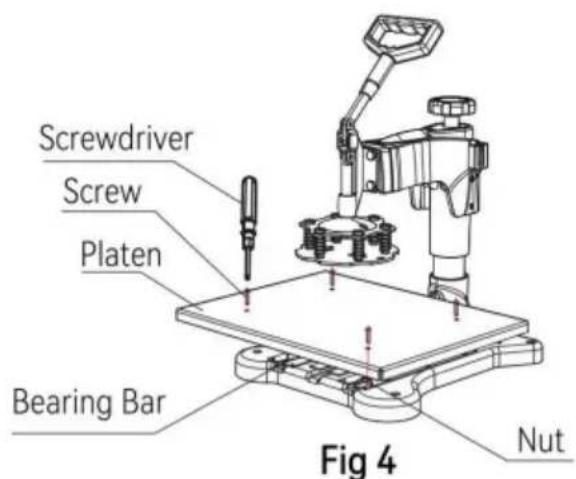
Fig 4
natural_image
Technical line drawing of a mechanical device with no visible text or symbolsFig 8

natural_image
Technical diagram of a mechanical assembly with a magnified inset showing a connector and directional arrows (no text or symbols)Fig 9
natural_image
Technical line drawing of a robotic arm with rotating base and mounting base (no text or symbols)Rotate the heating platen to one side
natural_image
Technical illustration of a robotic arm with mechanical components and a downward arrow indicating motion (no text or symbols)Pull out the lower panel, place the clothes flat on the platen, and place the pattern on the clothes.
4

natural_image
Diagram of a mechanical component with a rotating arrow, enclosed in a circular frame (no text or symbols)Rotate this switch to adjust pressure

natural_image
Technical line drawing of a mechanical device with a rotating arm and control panel (no text or symbols)METHODE DE FONCTIONNEMENT DU CONTROLEUR DE TEMPERATURE INTELLIGENT

Turn off the power and pull out the mat. It is recommended to wear heat-resistant gloves when removing clothes or remove them after 2-3 minutes. Be careful of hot heat.

natural_image
Technical line drawing of a robotic machine with a control panel and a close-up view of its base (no text or symbols)Rotate the heat transfer board to the side
3

natural_image
Simple line drawing of two overlapping rings (no text or symbols)Choose the right size Plate Press.

combination
separate
4

natural_image
Technical line drawing of a robotic arm and base platform assembly (no text or symbols)P and Q


natural_image
Technical illustration of a robotic arm operating on a plate with a circular base (no text or symbols)plate

natural_image
Cute cartoon panda inside concentric circles with stars (no text or symbols)Patterned plate
REEMPLACER LE TAPIS DE LA PLAQUE DE CUISSON


natural_image
Technical line drawing of a robotic machine with a control panel and a close-up view of its mechanical component (no text or symbols present)Rotate the heat transfer board to the side
REEMPLACER LE TAPIS DE CUISSON
3 Unscrew the four butterfil screws.at bottom
4
natural_image
Technical line drawing of a mechanical device with no visible text or symbolsLift the cushion up
5

natural_image
Technical line drawing of a mechanical clamp or bracket with mounting holes (no text or symbols)Install the backing pad (part 4)
6

Use the screwdriver 4 to tighten the 2 screws just removed and put the cap on


natural_image
Mechanical clamp device with lever mechanism and rotation arrow (no text or symbols)
DÉPANNAGE POUR LA QUALITÉ DU TRANSFERT
C/O YH Consulting Limited Bureau 147, Centurion House,
Route de Londres, Staines-upon-Thames, Surrey, TW18 4AX
VEVOR®
TOUGH TOOLS, HALF PRICE
natural_image
Technical line drawing of a mechanical device with a lever and base platform (no text or symbols)HULP NODIG? NEEM CONTACT MET ONS OP!
natural_image
Close-up of a metallic connector with black cap and flange (no text or symbols visible)
natural_image
Close-up of a metallic connector with a circular port, mounted on a black surface (no visible text or symbols)FCC-INFORMATIE
Machine Translated by Google
ONDERDELENLIJST

HOE U UW NIEUWE HITTEPERS KALIBREERT
| Deel | ABCDE | JKLM | FGHI | ||||||||||
| 5IN1 | |||||||||||||
| Deel | NOPQRS | TUVWXY | |||||||||||
| 5IN1 | |||||||||||||
| Deel | ABCD | EFGHI | JKLM | |||||||||
| 8IN1 | ÿ | ÿ | ÿ | ÿ | ÿ | ÿ | ÿ | ÿ | ÿ | ÿ | ÿ | ÿ |
| Deel | NOPQ | RSTU | VWXY | |||||||||
| 8IN1 | ÿ | ÿ | ÿ | ÿ | ÿ | ÿ | ÿ | ÿ |
Fig 1

Fig 3

Fig 4
natural_image
Technical line drawing of a mechanical device with red motion arrows indicating rotational movement (no text or symbols)Fig 8
natural_image
Technical diagram of a mechanical assembly with a magnified inset showing a component being inserted (no text or symbols present)Fig 9
natural_image
Technical line drawing of a robotic arm with rotating base and mounting base (no text or symbols)Rotate the heating platen to one side

natural_image
Technical line drawing of a robotic arm with a base and mounting base, showing mechanical components and a downward arrow indicating motion (no text or symbols present)Pull out the lower panel, place the clothes flat on the platen, and place the pattern on the clothes.
4

natural_image
Diagram of a mechanical component with a rotating arrow, enclosed in a circular frame (no text or symbols)Rotate this switch to adjust pressure

natural_image
Technical line drawing of a mechanical device with a control panel and digital display (no text or symbols)INTELLIGENTE TEMPERATUURREGELAAR BEDIENINGSMETHODE

Turn off the power and pull out the mat. It is recommended to wear heat-resistant gloves when removing clothes or remove them after 2-3 minutes. Be careful of hot heat.
Let

natural_image
Technical line drawing of a robotic machine with a control panel and a close-up view of its mechanical component (no text or symbols)Rotate the heat transfer board to the side
3

natural_image
Simple line drawing of two overlapping rings (no text or symbols)Choose the right size Plate Press.

combination

separate
4

natural_image
Technical line drawing of a robotic arm and base platform assembly (no text or symbols)P and Q


natural_image
Technical illustration of a robotic arm operating on a plate with a circular base (no text or symbols)plate

natural_image
Cute cartoon panda inside concentric circles with stars (no text or symbols)Patterned plate

natural_image
Technical line drawing of a robotic machine with a control panel and a close-up view of its mechanical component (no text or symbols)Rotate the heat transfer board to the side
Vervang de bakdopmat
3 Unscrew the four butterfil screws.at bottom

4

natural_image
Technical line drawing of a mechanical device with no visible text or symbolsLift the cushion up
5

natural_image
Simple line drawing of a mechanical clamp or bracket with a handle and mounting holes (no text or symbols)Install the backing pad (part 4)
6
Use the screwdriver 4 to tighten the 2 screws just removed and put the cap on
natural_image
Technical line drawing of a mechanical assembly with no visible text or symbolsPROBLEMEN OPLOSSEN VOOR OVERDRACHTKWALITEIT
C/O YH Consulting Limited Kantoor 147, Centurion House, Londen Road, Staines-upon-Thames, Surrey, TW18 4AX
VEVOR®
TOUGH TOOLS, HALF PRICE
Technische ondersteuning en e- garantiecertificaat www.vevor.com/support
VEVOR®
TOUGH TOOLS, HALF PRICE
natural_image
Technical line drawing of a mechanical device with a lever and base platform (no text or symbols)BEHÖVER HJÄLP? KONTAKTA OSS!
natural_image
Close-up of a metallic connector with black cap and flange (no text or symbols visible)
natural_image
Close-up of a metallic connector with a circular port, mounted on a black surface (no visible text or symbols)FCC-INFORMATION
| B | C | D |
| F | F | G | H |
| I | J | K | L |
| M | N | O | nove the head of the Phillips screwdriver180 degrees to replace it with a flat-head |
P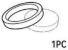 | Q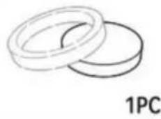 | R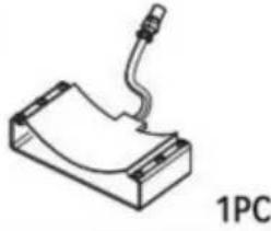 | S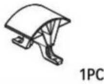 |
| U | V | W |
X | Y | ||
HUR DU KALIBRERAR DIN NYA VÄRMEPRESS
| Del ABCDE JKLM | FGHI | |||||||||||
| ÿ | ÿ | ÿ | ÿ | ÿ | ÿ | ÿ | ÿ | ÿ5IN1ÿÿ | ÿ | ÿ | ||
| Del NOPQRS | TUVWXY | |||||||||||
| 5IN1 | ÿÿÿÿ | ÿ | ÿ | ÿÿ | ÿ | |||||||
| Del A | BCDE | FGHI | JKLM | |||||||||||
| 8IN1 | ÿ | ÿ | ÿ | ÿ | ÿ | ÿ | ÿ | ÿ | ÿ | ÿ | ÿ | ÿ | ÿ | ÿ |
| Del NOPQR | RSTUV | VWXY | ||||||||||||
| 8IN1 | ÿ | ÿ | ÿ | ÿ | ÿ | ÿ | ÿ | ÿ | ÿ | |||||
Fig 1

Fig 3

Fig 4
natural_image
Technical line drawing of a mechanical device with red motion arrows indicating rotational movement (no text or symbols)Fig 8

natural_image
Technical diagram of a mechanical assembly with a magnified inset showing a component being inserted (no text or symbols present)Fig 9
natural_image
Technical line drawing of a robotic arm with rotating base and mounting base (no text or symbols)Rotate the heating platen to one side

natural_image
Technical line drawing of a robotic arm with mechanical components and a downward arrow indicating motion (no text or symbols)Pull out the lower panel, place the clothes flat on the platen, and place the pattern on the clothes.
4

natural_image
Diagram of a mechanical component with a rotating arrow, enclosed in a circular frame (no text or symbols)Rotate this switch to adjust pressure
natural_image
Technical line drawing of a mechanical device with a lever and control panel (no text or symbols)INTELLIGENT TEMPERATURREGLERINGSMETOD

Turn off the power and pull out the mat. It is recommended to wear heat-resistant gloves when removing clothes or remove them after 2-3 minutes. Be careful of hot heat.

natural_image
Technical line drawing of a robotic machine with a control panel and a close-up view of its mechanical component (no text or symbols)Rotate the heat transfer board to the side
3

natural_image
Simple line drawing of two overlapping rings (no text or symbols)Choose the right size Plate Press.

combination

separate
4

natural_image
Technical line drawing of a robotic arm and base platform assembly (no text or symbols)P and Q


natural_image
Technical illustration of a robotic arm operating on a plate with a circular base (no text or symbols)plate

natural_image
Cute cartoon panda inside concentric circles with stars (no text or symbols)Patterned plate
BYT BAKBÄTTMATTA
natural_image
Technical line drawing of a robotic machine with a control panel and a close-up view of its mechanical component (no text or symbols)Rotate the heat transfer board to the side
BYT BAKKLÄPSMATTA
3 Unscrew the four butterfil screws.at bottom

4

natural_image
Technical line drawing of a mechanical device with no visible text or symbolsLift the cushion up
5
natural_image
Technical line drawing of a mechanical clamp or bracket with mounting holes (no text or symbols)Install the backing pad (part 4)
6

Use the screwdriver 4 to tighten the 2 screws just removed and put the cap on

natural_image
Technical line drawing of a mechanical assembly with no visible text or symbolsInstallera H till del T.
FELSÖKNING FÖR ÖVERFÖRINGSKVALITET
C/O YH Consulting Limited Office 147, Centurion House,
London Road, Staines-upon-Thames, Surrey, TW18 4AX
VEVOR®
TOUGH TOOLS, HALF PRICE
natural_image
Technical line drawing of a mechanical device with a lever and base platform (no text or symbols)natural_image
Close-up of a metallic connector with black cap and flange (no text or symbols visible)
natural_image
Close-up of a metallic connector with a circular port, mounted on a black surface (no visible text or symbols) | B | C | D |
| F | F | G | H |
| I | J | K | L |
| M | N | O | nove the head of the Phillips screwdriver180 degrees to replace it with a flat-head |
| P | Q | R | S |
| U | V | W |
| X | Y | ||
CÓMO CALIBRAR SU NUEVA PRENSA TÉRMICA
| Parte | ABCDE JKLM | IGFHI | |||||||||||
| 5 EN | 1 √ | √√ √ | √√ | √ | √ | √ | √ | √√ | √ | ||||
| Parte | NOPQRS | TUVWXY | |||||||||||
| 5 EN 1 | √√√ | √ | √ | √ | √√ | √ | |||||||
| Parte | ABCDEFGHI JKLM | ||||||||||||
| 8 EN | 1 √ | √ √ | √ | √ √ | √ | √ | √ | √ √ | √√ | ||||
| Parte | NOPQRSTUVWXY | ||||||||||||
| 8 EN | 1 √ | √ √ √ | √ | √ | √ | √√ | √ | ||||||
Fig 1

Fig 3
natural_image
Technical line drawing of a mechanical device with red motion arrows indicating rotational movement (no text or symbols)Fig 8

natural_image
Technical diagram of a mechanical assembly with a magnified inset showing a connector and directional arrows (no text or symbols)Fig 9
natural_image
Technical line drawing of a robotic arm with rotating base and mounting base (no text or symbols)Rotate the heating platen to one side

natural_image
Technical line drawing of a robotic arm with mechanical components and a downward arrow indicating motion (no text or symbols)Pull out the lower panel, place the clothes flat on the platen, and place the pattern on the clothes.
4

natural_image
Diagram of a mechanical component with a rotating arrow, enclosed in a circular frame (no text or symbols)Rotate this switch to adjust pressure

natural_image
Technical line drawing of a mechanical device with a control panel and digital display (no text or symbols)
Turn off the power and pull out the mat. It is recommended to wear heat-resistant gloves when removing clothes or remove them after 2-3 minutes. Be careful of hot heat.
Nota

natural_image
Technical line drawing of a robotic arm operating a machine, with an arrow indicating motion (no text or symbols present)Rotate the heat transfer board to the side
3

natural_image
Simple line drawing of two overlapping rings (no text or symbols)Choose the right size Plate Press.

combination

separate
4
natural_image
Technical line drawing of a robotic arm and base platform assembly (no text or symbols)P and Q


natural_image
Technical illustration of a robotic arm operating on a plate with a circular base (no text or symbols)plate

natural_image
Cute cartoon panda inside concentric circles with stars (no text or symbols)Patterned plate
REEMPLAZO DE LA BANDEJA PARA HORNEADO


natural_image
Technical line drawing of a robotic machine with a control panel and a close-up view of its mechanical component (no text or symbols present)Rotate the heat transfer board to the side
REEMPLAZO DE LA TAPETE DE HORNEADO
3 Unscrew the four butterfil screws.at bottom

4

natural_image
Technical line drawing of a mechanical device with no visible text or symbolsLift the cushion up
5
natural_image
Simple line drawing of a mechanical clamp or bracket with a handle and mounting holes (no text or symbols)Install the backing pad (part 4)
6

Use the screwdriver 4 to tighten the 2 screws just removed and put the cap on

natural_image
Technical line drawing of a mechanical assembly with no visible text or symbolsC/O YH Consulting Limited Oficina 147, Centurion House,
Carretera de Londres, Staines-upon-Thames, Surrey, TW18 4AX
VEVOR®
TOUGH TOOLS, HALF PRICE