H-10296 - Wardrobe Uline - Free user manual and instructions
Find the device manual for free H-10296 Uline in PDF.

User questions about H-10296 Uline
0 question about this device. Answer the ones you know or ask your own.
Ask a new question about this device
Download the instructions for your Wardrobe in PDF format for free! Find your manual H-10296 - Uline and take your electronic device back in hand. On this page are published all the documents necessary for the use of your device. H-10296 by Uline.
USER MANUAL H-10296 Uline
TOOLS NEEDED
Phillips
Screwdriver
Rubber Mallet
Drill
(Optional)
5/16" Drill Bit (Optional)

Two Person Assembly Recommended
natural_image
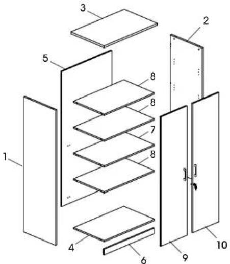
Line drawing of a two-door cabinet with a door handle (no text or symbols)PARTS
text_image
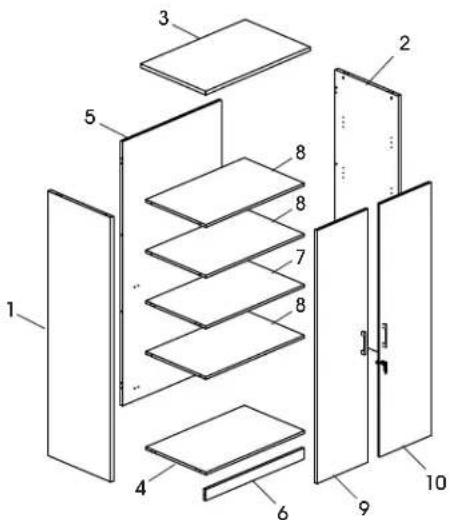
Exploded view diagram of a multi-panel storage or ventilation system with numbered components| # DESCRIPTION QTY | |
| 1 Left Side Panel 1 | |
| 2 Right Side Panel 1 | |
| 3 Top Panel 1 | |
| 4 Bottom Panel 1 | |
| 5 Back Panel 1 | |
| 6 Skirt Panel 1 | |
| 7 Fixed Shelf 1 | |
| 8 Shelf | 3 |
| 9 Left Door | 1 |
| 10 Right Door | 1 |
A
Adjustable Glide x 4
B
Metal Handle x 2
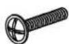
M4 x 22 mm Bolt x 4
D
Cam Lock Pin x 29
E

Cam Lock x 29
F

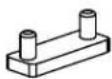
L-Bracket x 1

S-Bracket x 1

M3 x 16 mm Screw x 4
Lock x 1

M3.5 x 14 mm Screw x 2
G
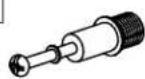
Dowel x 22
H

Shelf Dowel x 12
I

Cam Lock Cap x 29
J
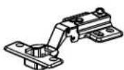
Hinge Wing x 8
K
Door Plug x 1
R
Wall Anchor Kit x 1

M4 x 10 mm Bolt x 16

M4 x 14 mm Screw x 32
ASSEMBLY

NOTE: Assemble unit on a smooth, non-marring surface to prevent scratching. Check that all parts are included.

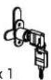
IMPORTANT! Turn cam lock 1/4 to the right to lock.
IMPORTANT! FUNCTION OF CAM LOCK

Ensure the arrow is pointing toward edge of panel before inserting into the panel's hole.

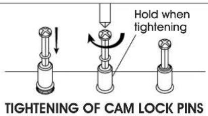
IMPORTANT! Cam lock pins must be tightened once inserted into panel. To tighten cam lock pins, grasp lower part of cam lock pin and tighten using a Phillips screwdriver.
text_image
Hold when tightening TIGHTENING OF CAM LOCK PINS
NOTE: Use Phillips screwdriver to tighten cam locks, cam lock pins and screws.

NOTE: Cam lock caps (I) can be applied once cam locks are tightened for a finished look.
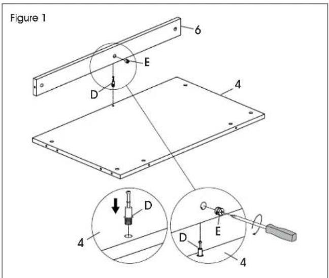
- Install one cam lock pin (D) in bottom panel (4). Insert one cam lock (E) into corresponding holes in skirt panel (6). Fit bottom panel and skirt panel together and tighten cam locks. (See Figure 1)
text_image
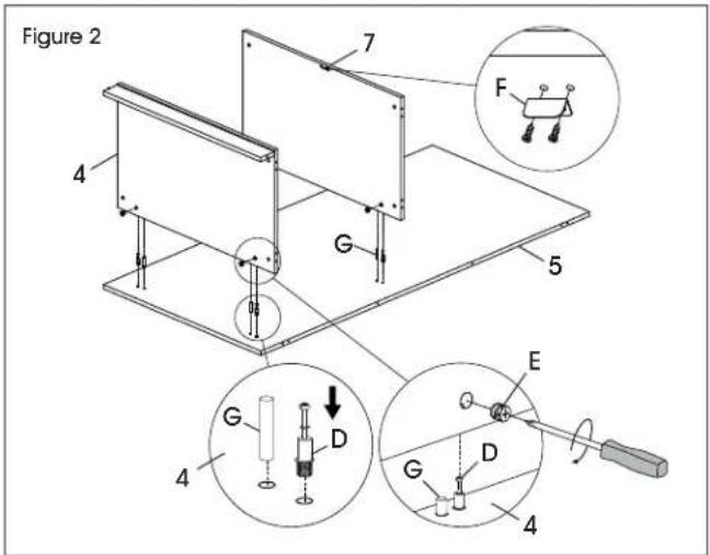
Figure 1 6 E D 4 4 D D E 4- Insert four cam lock pins (D) and four dowels (G) into back panel (5). Insert four cam locks (E) into bottom panel (4) and fixed shelf (7). Attach bottom panel and fixed shelf and tighten cam locks using a Phillips head screwdriver. (See Figure 2)
- Align holes on L-bracket (F) with pre-drilled holes in fixed shelf (7). Insert two M3 x 16 mm screws (F) and attach using Phillips head screwdriver. (See Figure 2)
text_image
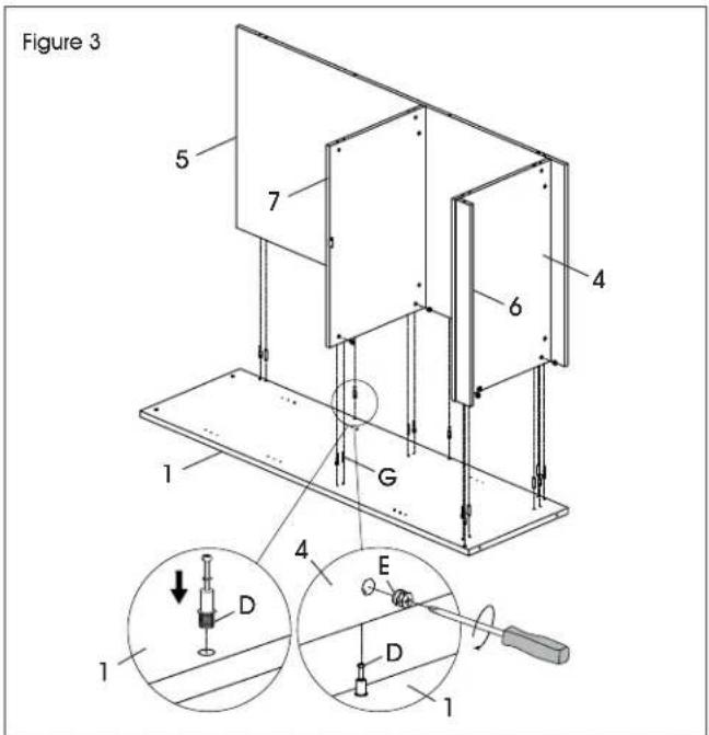
Figure 2 7 F 4 G 5 E 4 G D D G 4- Insert nine cam lock pins (D) and six dowels (G) into left side panel (1). Insert nine cam locks (E) into bottom panel (4), fixed shelf (7), back panel (5) and skirt panel (6). Attach panels and tighten cam locks using a Phillips screwdriver. (See Figure 3)
text_image
Figure 3 5 7 4 6 1 G 4 E D 1 1 1ASSEMBLY CONTINUED
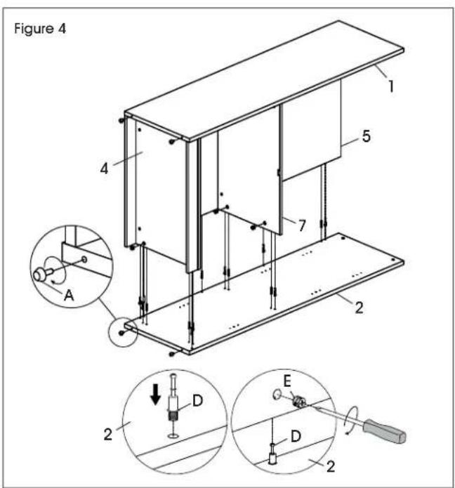
- Insert nine cam lock pins (D) and six dowels (G) into right side panel (2). Insert nine cam locks (E) into bottom panel (4), fixed shelf (7), back panel (5) and skirt panel (6). Attach panels and tighten cam locks using a Phillips head screwdriver. (See Figure 4)
- Insert adjustable glides (A) into bottom of side panels. (See Figure 4)
text_image
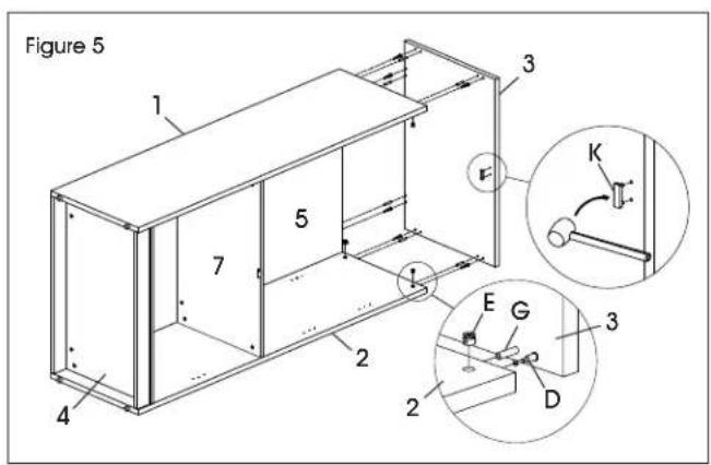
Figure 4 1 5 4 7 2 A E D D 2- Align holes on door plug (K) with pre-drilled holes in top panel (3) and gently tap with a rubber mallet to insert. Insert six cam lock pins (D) and six dowels (G) into top panel. Insert six cam locks (E) into back panel (5), right side panel (2) and left side panel (1). Attach top panel and tighten cam locks using a Phillips screwdriver. (See Figure 5)
text_image
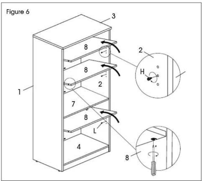
Figure 5 1 3 5 7 2 4 2 E G 3 K D- Place cabinet upright. Insert 12 shelf dowels (H) into side panels. Place shelves (8) inside cabinet and ensure shelf supports lower onto shelf dowels. Tighten shelf supports in underside of shelves for a secure fit. (See Figure 6)
text_image
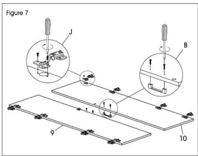
Figure 6 1 2 3 8 8 2 7 8 L 4 8 2 H- Place left door (9) and right door (10) panels on a smooth, non-marring surface to prevent scratching. Align holes in door hinge wing (J) with pre-drilled holes in door panels. Insert two M4 x 10 mm bolts (J) and tighten using a Phillips head screwdriver or drill. Repeat for seven remaining hinges. (See Figure 7)
- Attach handles (B) to the outside of door panels using M4 x 22 mm bolts (B) and a Phillips head screwdriver. (See Figure 7)
text_image
Figure 7 J B 9 10ASSEMBLY CONTINUED
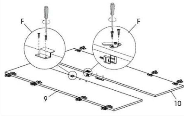
- Align holes on S-bracket (F) with pre-drilled holes on left door (9). Insert two M3 x 16 mm screws (F) and attach using a Phillips screwdriver or drill. (See Figure 8)
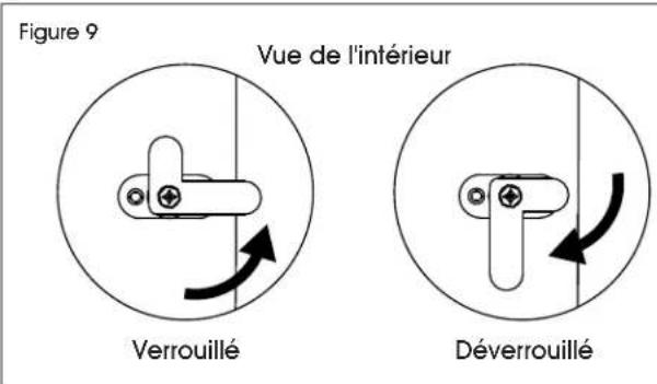
- Align holes on lock (F) with pre-drilled holes on right door (10). Insert two M3.5 x 14 mm screws (F) and attach using a Phillips head screwdriver or drill. (See Figures 8-9)

NOTE: Refer to Figure 9 for correct orientation of lock.
Figure 8
text_image
F F 9 10Figure 9
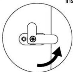
natural_image
Simple line drawing of a mechanical lever with a circular motion indicator (no text or symbols)Locked
Inside View
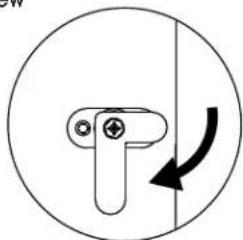
natural_image
Simple line drawing of a mechanical component with an arrow indicating rotational motion (no text or symbols)Unlocked
- Using two people, hold door panel in line with side panel. Attach frame hinge wing (J) to inside of side panels using four M4 x 14 mm screws (J). Repeat for seven remaining hinges. (See Figure 10)

NOTE: Side panels include two pre-drilled holes for alignment. Attach doors using the pre-drilled holes first. Remaining wood screws can be installed without pre-drilling holes in the side panel.
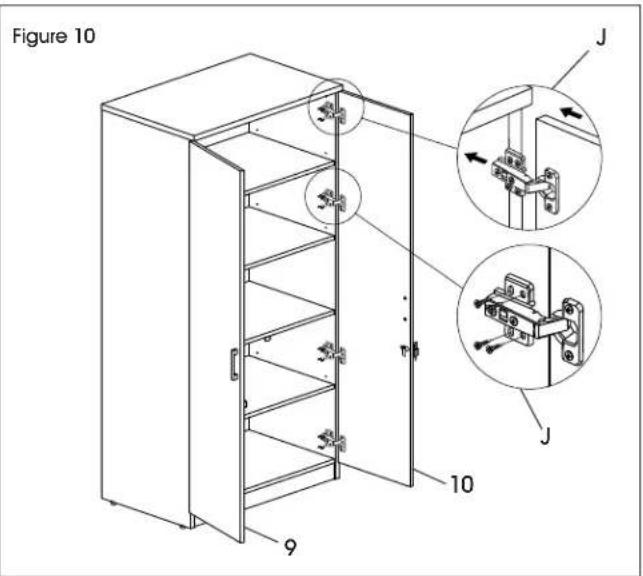
text_image
Figure 10 J J 10 9- Once door panels are attached, hinge may need to be adjusted to align the doors. To adjust the depth of the doors, tighten or loosen the rear screw in the hinge. To adjust the angle of the doors, tighten or loosen the center screw in the hinge. (See Figure 11)
Figure 11
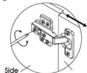
text_image
SidePanel
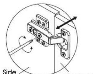
text_image
Side Power DisPanel
Door Depth Door Angle
ASSEMBLY CONTINUED
- Attach one bracket of wall anchor (R) to back of top of cabinet using two M4 x 20 mm screws. Mark holes on wall where plastic anchors are to be located. Drill holes using 5/16" drill bit. Mount opposite bracket of wall anchor to wall with two M4 x 40 mm screws and two plastic anchors. Tighten cable tie to prevent tipping. (See Figure 12)
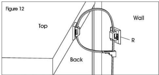
text_image
Figure 12 Top Back Wall R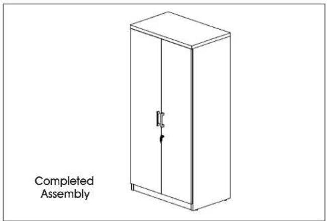
text_image
Completed Assemblynatural_image
Line drawing of a cabinet with two doors and a handle (no text or symbols)text_image
Exploded view diagram of a multi-panel storage or door assembly with numbered components| # DESCRIPCIÓN CANT. | |
| 1 Panel Lateral Izquierdo 1 | |
| 2 Panel Lateral Derecho 1 | |
| 3 Panel Superior 1 | |
| 4 Panel Inferior 1 | |
| 5 Panel Posterior 1 | |
| 6 Moldura | 1 |
| 7 Repisa Fija | 1 |
| 8 Repisa | 3 |
| 9 Puerta Izquierda | 1 |
| 10 Puerta Derecha | 1 |
natural_image
Line drawing of a two-door cabinet with a door handle and arrow indicating left side (no text or symbols)PIÈCES
text_image
Exploded view diagram of a multi-panel storage or door assembly with numbered componentstext_image
Figure 1 6 E D 4 4 D E 4text_image
Figure 2 7 F 4 G 5 E G D G D 4text_image
Figure 3 5 7 4 6 1 G 4 E D 1MONTAGE SUITE
text_image
Diagram showing two experimental setups with labeled components and a downward arrow indicating direction of movement or force.text_image
Figure 5 1 3 5 7 2 4 E G 3 2 D Ktext_image
Figure 7 J B 9 10MONTAGE SUITE
text_image
Figure 8 F F 9 10