
H-5839 - Heating Uline - Free user manual and instructions
Find the device manual for free H-5839 Uline in PDF.

User questions about H-5839 Uline
0 question about this device. Answer the ones you know or ask your own.
Ask a new question about this device
Download the instructions for your Heating in PDF format for free! Find your manual H-5839 - Uline and take your electronic device back in hand. On this page are published all the documents necessary for the use of your device. H-5839 by Uline.
USER MANUAL H-5839 Uline
natural_image
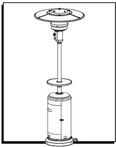
Technical line drawing of a vertical cylindrical industrial device with a circular top and base, no text or symbols present.SAFETY

DANGER! FOR YOUR SAFETY:
If you smell gas:
- Shut off gas to the appliance.
- Extinguish any open flame.
- If odor continues, keep away from the appliance and immediately call your gas supplier or fire department.

WARNING! Do not store or use gasoline or other flammable vapors and liquids in the vicinity of this or any other appliance. An LP cylinder not connected for use shall not be stored in the vicinity of this or any other appliance.

WARNING! For outdoor use only.

DANGER! CARBON MONOXIDE HAZARD.
This appliance can produce carbon monoxide, which has no odor. Using it in an enclosed space can kill you. Never use this appliance in an enclosed space, such as a camper, tent or home.


Please read and understand these entire instructions before attempting to assemble, operate or install the product.
These instructions contain important information about the assembly, operation and maintenance of this patio heater. General safety information is presented in these first few pages and is also located throughout the instructions. Keep these instructions for future reference and to educate new users of this product. These instructions should be read in conjunction with the labeling on the product. Safety precautions are essential when any mechanical or propane-fueled equipment is involved. These precautions are necessary when using, storing and servicing this item. Using this equipment with the respect and caution demanded will reduce the possibilities of personal injury or property damage.

DANGER! Failure to comply with the precautions and instructions provided with this heater can result in death, serious bodily injury and property loss or damage from hazards of fire, explosion, burn, asphyxiation and/or carbon monoxide poisoning. Only persons who can understand and follow the instructions should use or service this heater.

DANGER! EXPLOSION/FIRE HAZARD.
- Keep solid combustibles, such as building materials, paper or cardboard, a safe distance away from the heater as recommended by the instructions.
- Provide adequate clearances around air openings into the combustion chamber.
SAFETY CONTINUED
- Never use the heater in spaces that do or may contain volatile or airborne combustibles, or products such as gasoline, solvents, paint thinner, dust particles or unknown chemicals.
- During operation, this product can be a source of ignition. Keep heater area free from combustible materials, gasoline, paint thinner, cleaning solvents and other flammable vapors and liquids. Do not use heater in areas with high dust content. Minimum heater clearances from combustible materials: three feet from the sides and two feet from the top.
DANGER! CARBON MONOXIDE HAZARD.

- This heater is a combustion appliance. All combustion appliances produce carbon monoxide (CO) during the combustion process. This product is designed to produce extremely minute, non-hazardous amounts of CO if used and maintained in accordance with all warnings and instructions. Do not block air flow into or out of the heater.
- Carbon monoxide (CO) poisoning produces flu-like symptoms, watery eyes, headaches, dizziness, fatigue and possibly death. You can't see it and you can't smell it. It's an invisible killer. If these symptoms are present during operation of this product, get fresh air immediately!
- For outdoor use only. Never use inside house, or other unventilated or enclosed areas.
- This heater consumes air (oxygen). Do not use in unventilated or enclosed areas to avoid endangering your life.
DANGER! EXPLOSION/FIRE HAZARD.
- Never store propane near high heat, open flames, pilot lights, direct sunlight, other ignition sources or where temperatures exceed 120°F.
- Propane vapors are heavier than air and can accumulate in low places. If you smell gas, leave the area immediately.
-
Never install or remove propane cylinder while heater is lit, near flame, pilot lights, other ignition sources or while heater is hot to touch.
-
This heater is red hot during use and can ignite flammables too close to the burner. Keep flammables at least three feet from sides and two feet from top. Keep gasoline and other flammable liquids and vapors well away from heater.
- Store the propane cylinder outdoors in a well ventilated space out of reach of children. Never store the propane cylinder in an enclosed area (house, garage, etc.). If heater is to be stored indoors, disconnect the propane cylinder for outdoor storage.

WARNING! Every use that may be made of heaters cannot be foreseen. Check with your local fire safety authority if you have questions about heater use. Other standards govern the use of fuel gases and heat-producing products for specific uses. Your local authorities can advise you about these.
If no local codes exist, follow National Fuel Gas Code, ANS Z223.1. In Canada, installation must conform to local codes. If no local codes exist, follow the current national standards of CANADA CAN/CGA-B 149.2.

WARNING! CALIFORNIA PROPOSITION 65. Combustion byproducts of this product contain chemicals known to the state of California to cause cancer, birth defects and other reproductive harm.

WARNING! BURN HAZARD.
- Never leave heater unattended when hot or in use.
- Keep out of reach of children.

WARNING! Do not store or use gasoline or other flammable vapors and liquids in the vicinity of this or any other appliance. An LP cylinder not connected for use shall not be stored in the vicinity of this or any other appliance.

WARNING! Improper installation, adjustment, alteration, service or maintenance can cause property damage, injury or death. Read the installation, operation and maintenance instructions thoroughly before installing or servicing this equipment.
SAFETY CONTINUED

WARNING! Certain materials or items, when stored under the heater, will be subjected to radiant heat and could be seriously damaged.

WARNING! This product is fueled by propane gas. Propane gas is invisible, odorless and flammable. An odorant is normally added to help detect leaks and can be described as a "rotten egg" smell. The odorant can fade over time so leaking gas is not always detectable by smell alone.
- Propane gas is heavier than air and leaking propane will sink to the lowest level possible. It can ignite by ignition sources including matches, lighters, sparks or open flames of any kind many feet away from the original leak. Use only propane gas set up for vapor withdrawal.
- Store or use propane gas in compliance with local ordinances and codes or with ANS/NFPA 58. Turn off propane when not in use.

CAUTION! SERVICE SAFETY.
- Keep all connections and fittings clean. Make sure propane cylinder valve outlet is clean.
- During set up, check all connections and fittings for leaks using soapy water. Never use a flame.
- Use as a heating appliance only. Never alter in any way or use with any device.

WARNING!
- Alert children and adults to the hazards of high surface temperatures. Stay away from these surfaces to avoid burning skin or igniting clothing.
- Carefully supervise young children when in the vicinity of the heater.
- Do not hang clothing or any other flammable materials from the heater, or place on or near the heater.
- Replace any guard or protective device removed for servicing the appliance prior to placing back in service.
- Installation and repair should be done by a qualified service person. The heater should be inspected before use and annually by a qualified service person. More frequent cleaning may be required as necessary.
- It is imperative that the control compartment, burners and circulating air passageway of the appliance be kept clean.
TOOL REQUIRED
Phillips Screwdriver (not included)
PARTS

M8 Flange Nut x 2
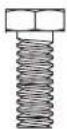
M8 x 16 mm
Bolt x 2

M5 x 8 mm
Screw x 4
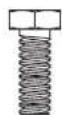
M6 x 10 mm
Bolt x 4

Small Flat Washer x 4
Reflector
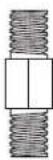
Spacer x 3
Large Washer x 9

Medium Flat Washer x 9

M6 x 10 mm
Screw x 9

Cap Nut x 9 Wing Nut x 3 Stainless Steel

Bolt x 4
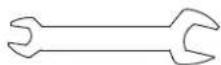
Wrench x 1 Reinforced
Ring x 1
Deck Ring x 1
ASSEMBLY
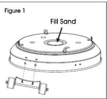
- Line up holes on the bracket of wheel assembly with the corresponding holes on base, then insert 16 mm bolts through holes. Hand tighten with flange nuts. Be sure the wheel assembly is parallel to the base. (See Figure 1)
text_image
Figure 1 Fill Sand
Note: To improve stability, the bucket (in base) can be filled with sand (not included).
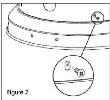
- Attach cylinder housing loosely to base with M5 x 8 mm screws. (See Figure 2)
text_image
Figure 2-
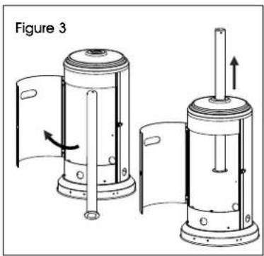
Open the preassembled door on cylinder housing and place post through the hole on the top. (See Figure 3)
-
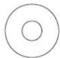
Secure post to cylinder housing using the reinforced ring, M6 x 10 mm bolts and four small flat washers. Fasten and cover with the deck ring. (See Figure 4)
natural_image
Technical illustration of two mechanical components with directional arrows indicating motion (no text or symbols)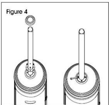
natural_image
Technical line drawing of two mechanical components with cylindrical pins and a circular component, labeled Figure 4 (no text or symbols on the diagram itself)ASSEMBLY CONTINUED
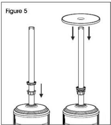
- Slide fastening nut down the post with the rounded side facing down. Next, slide the tightening spacer down the post with the smaller side facing down. Put the table on the post with the metallic side facing up. (See Figure 5)
natural_image
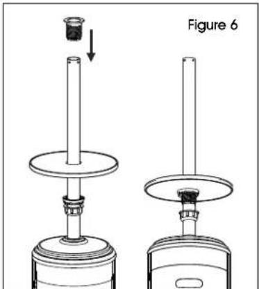
Diagram of two mechanical devices with arrows indicating motion or assembly, no text or symbols present- Insert the screw coupler on the post, inserting it through the middle of the table on the post. Thread the tightening spacer on the bottom of the table counterclockwise onto the screw coupler. Tighten securely to hold the table to the screw coupler. Thread the Tighten securely to lead fastening nut to adjust the post. (See Figure)
text_image
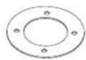
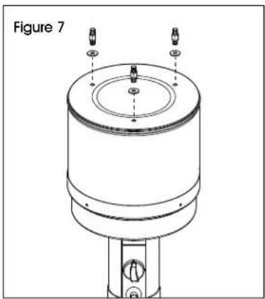
Figure 6- Attach reflector spacers and large washers to the top of head assembly. Tighten the reflector spacers. (See Figure 7)
natural_image
Technical line drawing of a mechanical component with mounting holes and a cylindrical body (no text or symbols)- Unscrew stainless steel bolts from head assembly. (See Figure 8)
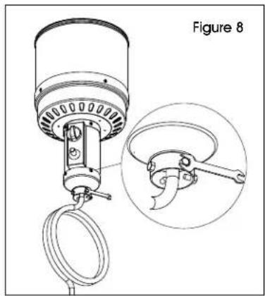
natural_image
Technical diagram of a mechanical device with a magnified inset showing a close-up detail (no text or symbols)- Insert hose of head assembly into post. Secure head assembly to post with stainless steel bolts. (See Figure 9)
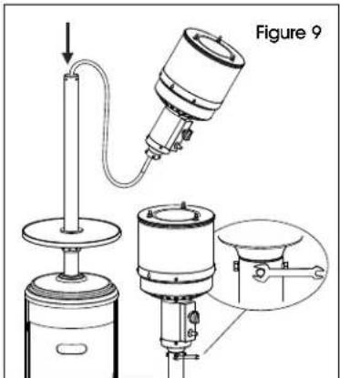
text_image
Figure 9
NOTE: The control knob on head assembly should be above the decal on post.
- Remove protective cover from reflector panel and reflector plate. (See Figure 10)

NOTE: In order to achieve proper alignment of reflector sections, it may be necessary to loosen the preassembled bolts prior to assembly and re
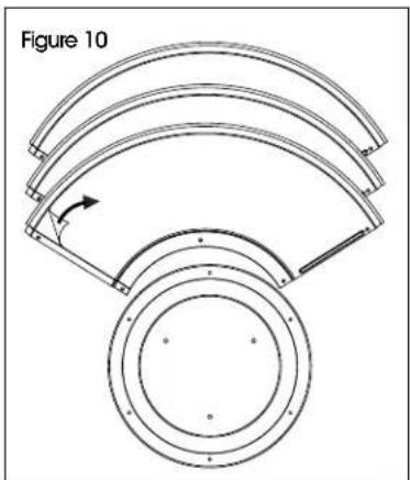
natural_image
Technical diagram of a curved mechanical component with concentric rings and a central rotating arrow (no text or symbols)ASSEMBLY CONTINUED
- Attach reflector panels together using M6 x 10 mm screws and small flat washers. Secure loosely with cap nuts. (See Figure 11)
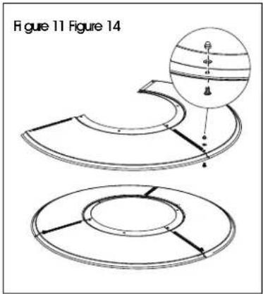
text_image
Figure 11 Figure 14- Attach reflector plate to reflector panels using M6 x 10 mm screws and medium flat washers. Secure loosely with cap nuts. Once properly aligned, tighten all screws and the preassembled bolts. (See Figure 12)
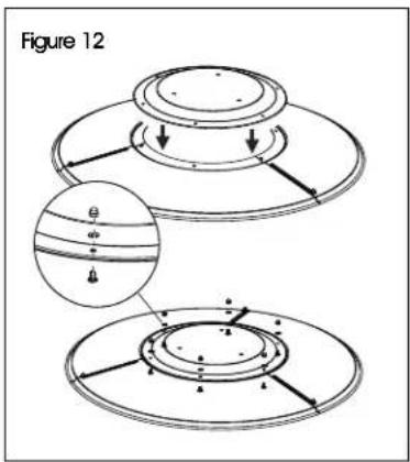
text_image
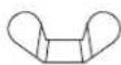
Figure 12- Slide three large washers over the threaded ends of reflector spacers. Attach reflector assembly to head assembly. Place three large washers over threaded ends of reflector spacers sticking out through reflector assembly and secure with wing nuts. (See Figure 13)
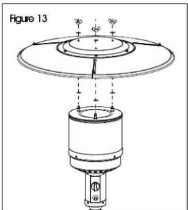
text_image
Figure 13
NOTE: Do not overtighten.
natural_image
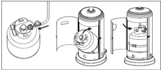
Technical line drawing of three mechanical components with no visible text or symbols- Screw gas hose and regulator onto propane cylinder (not included). Do not cross-thread. Place the propane cylinder into the cylinder housing, then close the door. (See Figure 14)

WARNING! Use a standard 20 lb. propane cylinder only. (approximately 12.2" (31 cm) in diameter and 17.9" (45.5 cm) tall. Use this heater only with a propane vapor withdrawal supply system. See chapter 5 of the standard for storage and handling of liquefied petroleum gas, ANS/NFPA 58. A local library or fire department should have this book. Storage of an appliance indoors is permissible only if the cylinder is disconnected and removed from the appliance. A cylinder must be stored indoors in a well-ventilated area out of the reach of children. A disconnected cylinder must have dust caps tightly installed and must not be stored in a building, garage or any enclosed area. The maximum inlet supply pressure: 250 psi. (1,750 kPa). The minimum inlet gas supply pressure: 25 psi (175 kPa). Manifold pressure with regulator provided: 11" W.C (2.74 kPa). The pressure regulator and hose assembly supplied with the appliance must be used. The installation must conform with local codes, or in the absence of local codes, with national fuel gas code, ANSI Z223.1/NFPA54, natural gas and propane installation code, CSA B149.1, or propane storage and handling code B149.2.
A dented, rusted or damaged propane cylinder may be hazardous and should be checked by your cylinder supplier. Never use a propane cylinder with a damaged valve connection. The propane cylinder must be constructed and marked in accordance with the specifications for LP-gas cylinders of the U.S. Department of Transportation (DOT) or the standard for cylinders, spheres and tubes for transportation of dangerous goods and commission, CAN/CSA-B339.
ASSEMBLY CONTINUED
The cylinder must have a listed overfilling prevention device.
The cylinder must have a connection device compatible with the connection for the appliance.
The cylinder used must include a collar to protect the cylinder valve.
Never connect an unregulated propane cylinder to the heater.
- Do not store a spare LP gas cylinder under or near this appliance.
- Never fill the cylinder beyond 80 percent full.
-
Place the dust cap on the cylinder valve outlet whenever the cylinder is not in use. Only install the type of dust cap on the cylinder valve that is provided with the cylinder valve. Other type of caps or plugs may result in leakage of propane.
-
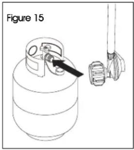
The knob on the LP tank must be closed. Make sure that the knob is turned clockwise to a full stop. The cylinder supply system must be arranged for vapor withdrawal. Check that the control knob on the control unit is turned off. Hold the regulator in one hand and insert the nipple into the
valve outlet. (See Figure 15) Be sure the nipple is centered in the valve outlet. The coupling nut connects to the large outside threads on the valve outlet.
- Hand-tighten the coupling nut clockwise until it comes to a full stop. Firmly tighten by hand only.
text_image
Figure 15To disconnect:
- Fully close the tank valve by turning clockwise. Turn the coupling nut counterclockwise until the regulator assembly detaches.
OPERATION
To check for a leak:
- Make 2-3 oz. leak check solution (one part liquid dishwashing detergent and three parts water).
- Apply several drops of solution where regulator connects to cylinder and to all hose and valve connections
- Make sure all patio heater and light valves are OFF.
- Turn cylinder valve ON.
If bubbles appear at any connection, there is a leak.
- Turn cylinder valve OFF.
- If leak is at regulator/cylinder valve connection: Disconnect, reconnect and perform another leak check. Apply the soapy solution to all hose and valve connections. If you continue to see bubbles after several attempts, cylinder valve is defective and should be returned to cylinder's place of purchase.
- If leak is at hose/regulator connection, this part is defective and you should contact the customer service department for replacement.
If NO bubbles appear at any connection, the connections are secure.

NOTE: Whenever gas connections are loosened or removed, user must perform a complete leak test.

DANGER! CARBON MONOXIDE HAZARD. For outdoor use only. Never use inside house, or other unventilated or enclosed areas. This heater consumes air (oxygen). Do not use in unventilated or enclosed areas to avoid endangering your life.

CAUTION! Do not attempt to operate until you have read and understand all general safety information in these instructions and all assembly is complete and leak checks have been performed.
OPERATION CONTINUED
- Your heater was designed and approved for outdoor use only. Do NOT use it inside a building, garage or any other enclosed area.
- Make sure surrounding areas are free of combustible materials, gasoline and other flammable vapors or liquids.
- Ensure that there is no obstruction to air ventilation. Be sure all gas connections are tight and there are no leaks.
- Be sure the cylinder cover is clear of debris. Be sure any component removed during assembly or servicing is replaced and fastened prior to starting.
BEFORE LIGHTING
- Heater should be thoroughly inspected before each use, and by a qualified service person at least annually. If relighting a hot heater, always wait at least 5 minutes.
- Inspect the hose assembly for evidence of excessive abrasion, cuts or wear. Suspected areas should be leak tested. If the hose leaks, it must be replaced prior to operation. Only use the replacement hose assembly specified by manufacturer.
- The pressure regulator and hose assembly supplied with the appliance must be used.
LIGHTING
- Turn gas cylinder valve to the "ON" position and place into the cylinder housing.
- Press and turn the control knob to high (maximum) position (counterclockwise 90°). (See Figure 16)
- Holding down the control knob, press the igniter button several times until the main flame is ignited. Release the control knob ten seconds after ignition.
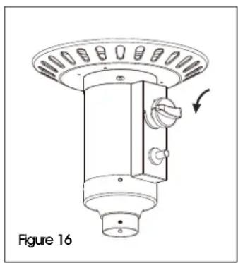
natural_image
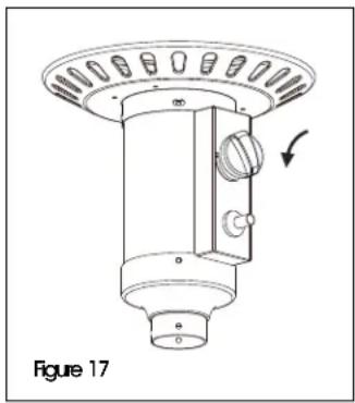
Technical line drawing of a mechanical component with a circular top and cylindrical base, labeled Figure 16 (no text or symbols on the diagram itself)- Turn the control knob to low (minimum) and leave it there for five minutes or more before turning the knob to desired temperature setting. (See Figure 17)
- If the burner flame goes out, turn off the heater and wait at least five minutes or more to let the gas dissipate before re-lighting to avoid gas explosion. Repeat St

NOTE: Improper operation can cause injury or property damage. If burner fails to remain lit, all valves should be closed and a waiting period of at least five minutes should pass before attempting to light.
If you experience any ignition problem, please consult troubleshooting on page 10.

CAUTION! Avoid inhaling fumes emitted from the heater's first use. Smoke and odor from the burning of oils used in manufacturing will appear. Both smoke and odor will dissipate after approximately 30 minutes. The heater should NOT produce thick black smoke.

NOTE: The burner may be noisy when initially turned on. Turn the knob to the level of heat desired.
text_image
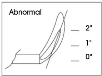
Abnormal — 2" — 1" — 0"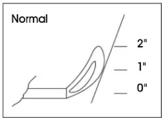
text_image
Normal 2" 1" 0"
WARNING! FOR YOUR SAFETY: Be careful when attempting to manually ignite this heater. Holding in the control knob for more than 10 seconds before igniting the gas will cause a ball of flame upon ignition.
natural_image
Technical line drawing of a mechanical component with a circular top and cylindrical base, labeled as Figure 17 (no text or symbols on the diagram itself)OPERATION CONTINUED
WHEN HEATER IS ON
Emitter screen will become bright red due to intense heat. The color is more visible at night. Burner will display tongues of blue and yellow flame. These flames should not be yellow or produce thick black smoke, indicating an obstruction of airflow through the burners. The flame should be blue with straight yellow tops. If excessive yellow flame is detected, turn off heater and consult troubleshooting on page 10.
RELIGHTING
- Turn control knob to "OFF."
- Repeat the "Lighting" steps on prior page.

WARNING! FOR YOUR SAFETY. Heater will be hot after use. Handle with extreme care.
SHUT DOWN
Turn control knob clockwise to "OFF" and disconnect regulator when heater is not in use.

NOTE: After use, some discoloration of the emitter screen is normal.

WARNING! FOR YOUR SAFETY:
- Do NOT touch or move heater for at least 45 minutes after use.
• Reflector is hot to the touch. - Allow reflector to cool before touching.
CARE AND MAINTENANCE
- Keep exterior surfaces clean.
- Use warm, soapy water for cleaning. Never use flammable or corrosive cleaning agents.
- While cleaning your unit, be sure to keep the area around the burner and pilot assembly dry at all times. Do not submerge the control valve assembly. If the gas control is submerged in water, do NOT use it. It must be replaced.
- Keep the appliance area clear and free from combustible materials, gasoline and other flammable vapors and liquids.
- Do not obstruct the flow of combustion and ventilation air.
- Keep the ventilation opening(s) of the cylinder enclosure free and clear from debris.
- Air flow must be unobstructed. Keep controls, burner and circulating air passageways clean.
- Spiders and insects can nest in burner or orifices. This dangerous condition can damage heater and render it unsafe for use. Clean burner holes by using a heavy-duty pipe cleaner. Compressed air may help clear away smaller particles.
- Carbon deposits may create a fire hazard. Clean dome and burner screen with warm, soapy water if any carbon deposits develop.

NOTE: In a salt-air environment (such as near an ocean), corrosion occurs more quickly than normal. Frequently check for corroded areas and repair them promptly.
- Use high-quality automobile wax to help maintain the appearance of the heater. Apply to exterior surfaces from the pole down. Do not apply to emitter screen or domes.
BETWEEN USES
- Turn Control Knob OFF.
- Disconnect LP source.
- Store heater upright in an area sheltered from direct contact with inclement weather (such as rain, sleet, hail, snow, dust and debris).
- If desired, cover heater to protect exterior surfaces and to help prevent buildup in air passages.

NOTE: Wait until heater is cool before covering.
DURING PERIODS OF EXTENDED INACTIVITY OR WHEN TRANSPORTING
- Turn Control Knob to "OFF."
- Disconnect LP source and move to a secure, well-ventilated location outdoors.
- Store heater upright in an area sheltered from direct contact with inclement weather (such as rain, sleet, hail, snow, dust and debris).
- If desired, cover heater to protect exterior surfaces and to help prevent buildup in air passages.
- Never leave LP cylinder exposed to direct sunlight or excessive heat.

NOTE: Wait until heater is cool before covering.
CARE AND MAINTENANCE CONTINUED
SERVICE
Only a qualified service person should repair gas passages and associated components.

CAUTION! Always allow heater to cool before attempting service.
TROUBLESHOOTING
| OPERATING ISSUE CAUSES RECOMMENDATIONS | ||
| Burner won't light. | 1. Propane cylinder is frosted over.2. Blockage in orifice.3. Control knob is not in "ON" position. | 1. Wait until the propane cylinder warms up and becomes unfrosted.2. Clear blockage.3. Turn control knob to "ON." |
| Burner flame is low. | 1. Gas pressure is low.2. Outdoor temperature is less than 40°F and tank is less than 1/4 full.3. Control knob fully "ON."4. Spiders and insects nest in burner or orifices. | 1. Turn cylinder valve "OFF" and replace cylinder.2. Use a full cylinder.3. Check burner and orifices for blockage.4. Clean burner and orifices. |
| Thick black smoke appears. | Blockage in burner. Remove blockage and clean burner inside and outside. | |
| Carbon buildup. | Dirt or film on reflector and burner screen. | Clean reflector and burner screen. |
natural_image
Technical line drawing of a vertical cylindrical industrial device with a circular top and base, no text or symbols present.SEGURIDAD

¡PELIGRO!
Si detecta olor a gas:
text_image
Technical diagram of a mechanical component with labeled parts and cross-sectional viewnatural_image
Technical line drawing of two mechanical components with cylindrical shafts and housing (no text or symbols)natural_image
Technical line drawing of a mechanical component with a circular top and cylindrical base, labeled 'Diagrama 16' (no text or symbols on the diagram itself)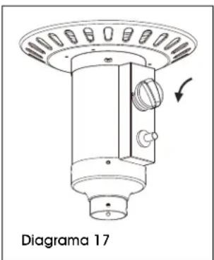
natural_image
Technical line drawing of a mechanical component with a circular top and base, labeled 'Diagrama 17' (no text or symbols on the diagram itself)text_image
Anormal — 2" — 1" — 0"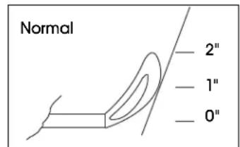
text_image
Normal — 2" — 1" — 0"
natural_image
Technical line drawing of a vertical cylindrical industrial device with a circular top and side-mounted base (no text or symbols)SÉCURITÉ

DANGER! POUR VOTRE SÉCURITÉ.
natural_image
Technical illustration of two mechanical components with directional arrows indicating motion (no text or symbols)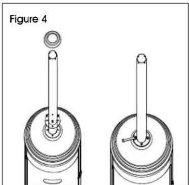
natural_image
Technical illustration of two mechanical components with cylindrical shafts and a circular end cap, labeled Figure 4 (no text or symbols on the diagram itself)MONTAGE SUITE
natural_image
Technical line drawing of a mechanical component with mounting holes and a central circular housing (no text or symbols)natural_image
Technical line drawing of a mechanical device with a magnified inset showing a close-up detail (no text or symbols)natural_image
Technical line drawing of a curved mechanical component with a circular base and radial arms, labeled 'Figure 10' (no text or symbols on the diagram itself)natural_image
Technical line drawing of two circular components with internal features, no text or symbols presenttext_image
Figure 12text_image
Figure 13text_image
Figure 14text_image
Figure 15natural_image
Technical line drawing of a mechanical component with a circular top and cylindrical base, labeled Figure 16 (no text or symbols on the diagram itself)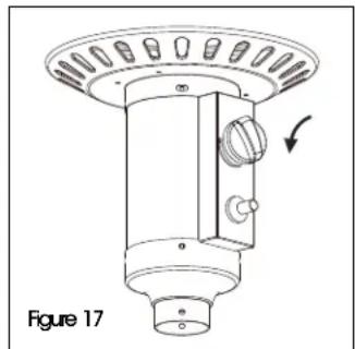
natural_image
Technical line drawing of a mechanical component with a circular top and cylindrical base, labeled as Figure 17 (no text or symbols on the diagram itself)FONCTIONNEMENT SUITE
text_image
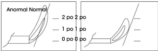
Anormal Normal — 2 po 2 po — 1 po 1 po — 0 po 0 po


